| GENX-1B ENGINE MANUAL | Dated: 06/27/2023 | |
| EM 72-00-01 , SPECIAL PROCEDURES 002 | ||
| FAN STATOR MODULE ASSEMBLY - SPECIAL PROCEDURE 002 - FORWARD MOUNT YOKE BUSHING RE-POSITIONING | ||
| GENX-1B ENGINE MANUAL | Dated: 06/27/2023 | |
| EM 72-00-01 , SPECIAL PROCEDURES 002 | ||
| FAN STATOR MODULE ASSEMBLY - SPECIAL PROCEDURE 002 - FORWARD MOUNT YOKE BUSHING RE-POSITIONING | ||
| * * * FOR ALL |
| TASK 72-00-01-800-802 |
| 1 . | Forward Mount Yoke Bushing Re-Positioning. |
| A. | This procedure provides instructions for re-positioning migrated forward mount yoke bushings. |
| B. | This procedure can be applied to multiple forward mount yoke bushings on the same mount yoke. |
| 2 . | Tools, Equipment, and Materials. |
| A. | Tools and Equipment. |
| (1) | Special Tools. None. |
| (2) | Standard Tools and Equipment. None. |
| (3) | Locally Manufactured Tools. |
|
| B. | Consumable Materials. |
|
| C. | Referenced Procedures. |
|
| D. | Expendable Parts. None. |
| E. | SPD Information. None. |
| F. | Special Solutions. None. |
| G. | Test Specimens. None. |
| 3 . | Dimensional Information. |
| A. | Refer to TASK 72-00-01-200-801 (72-00-01, INSPECTION 001). |
| 4 . | Setup Information. |
| A. | This procedure can be performed with the engine removed and the forward mount yoke installed or with the forward mount yoke removed. Refer to Figure 201, Figure 202, and Figure 203 for locally manufactured tools. |
| 5 . | Procedure. |
| Subtask 72-00-01-350-001 |
| A. | Push back the migrated bushing to its original position as follows: |
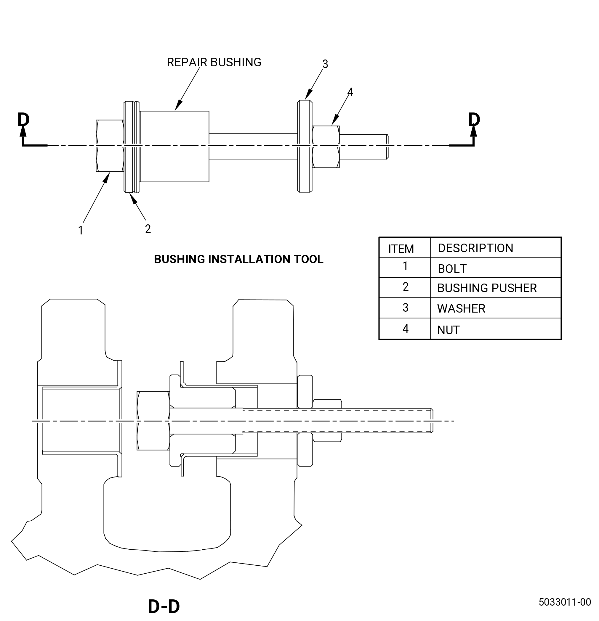
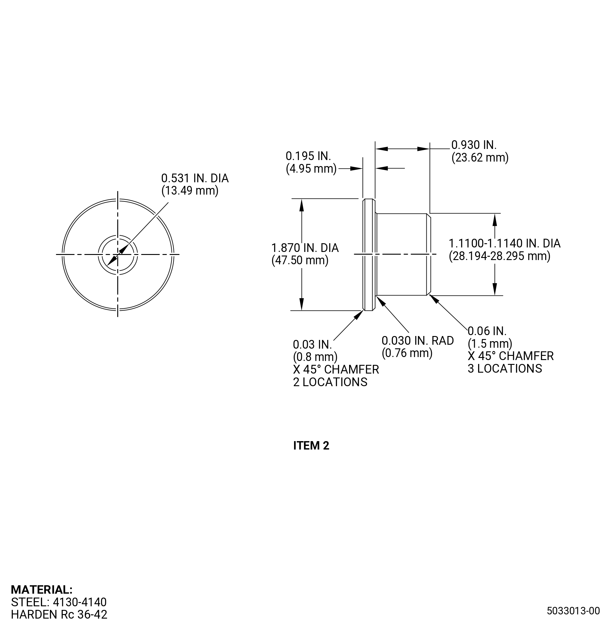
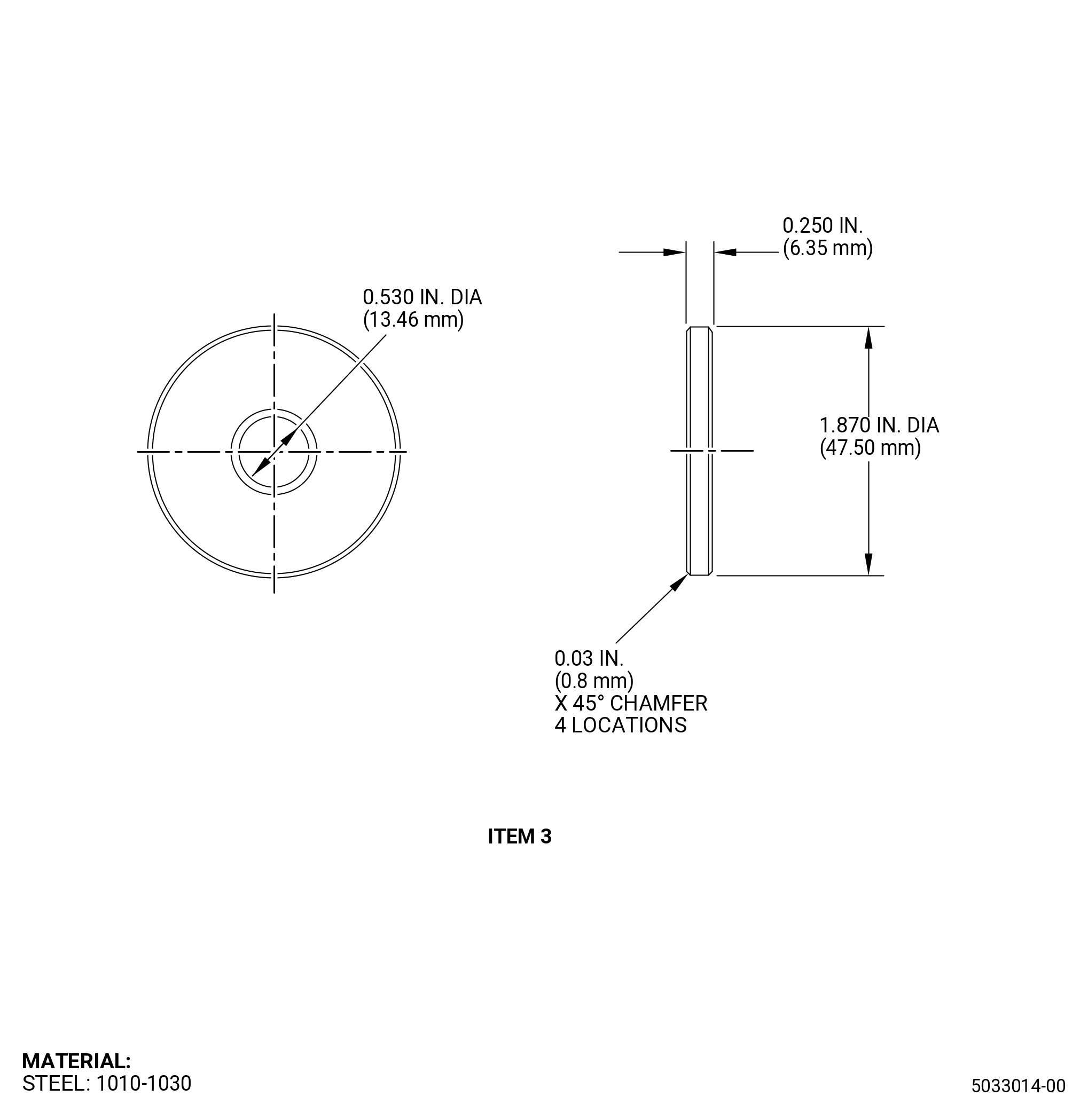
| (1) | If necessary, make the bushing installation tool. Refer to Figure 201. |
| WARNING: |
|
| WARNING: |
|
| WARNING: |
|
| (2) | Chill the migrated bushing with dry ice and C04-035 isopropyl alcohol for at least 30 minutes before it is pushed back into correct position. |
| (3) | If possible apply a thin coat of D6Y28A1 lubricant or C02-071 lubricant (C02-060 lubricant is a suitable substitute) around the exposed bore area prior to push the bushing back. |
| (4) | Install the bushing pusher (item 2) in the migrated bushing. Refer to Figure 201. |
| (5) | Install the bolt (item 1) through the bushing pusher (item 2) and mount lug. Refer to Figure 201 and do as follows: |
| (a) | Install the bolt (item 1) from the face of the mount lug that you will not repair. |
| (6) | Install the washer (item 3) and nut (item 4) to the face of the mount lug that you will repair. Refer to Figure 201 and do as follows: |
| (a) | Install the washer (item 3) to the bolt (item 1) at the face of the mount lug. |
| (b) | Install the nut (item 4) to the bolt (item 1) from the face of the mount lug to force the washer (item 3) against the mount lug face. |
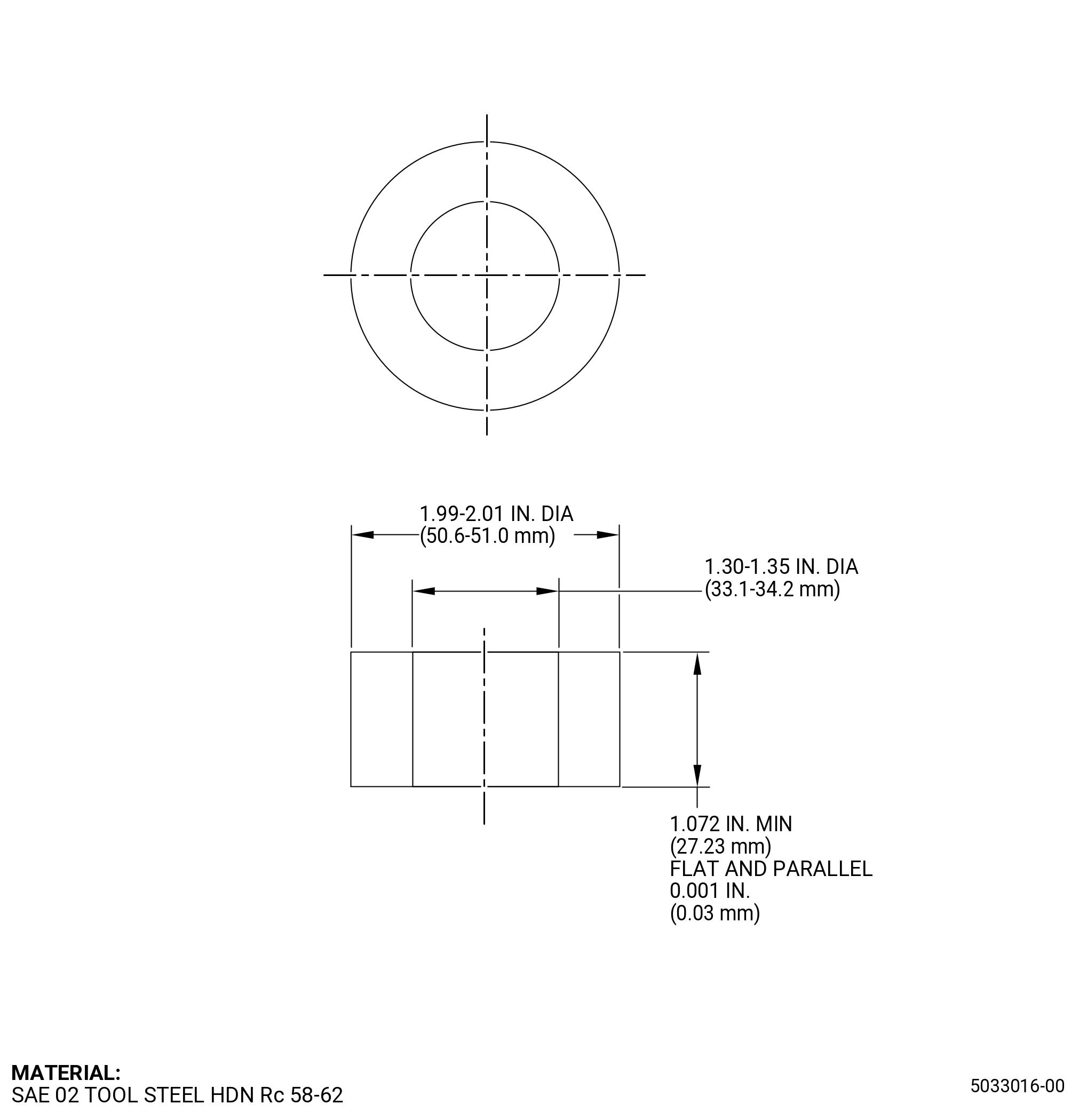
| (7) | Install the lug spacer between the mount lugs and use C10-155 shims as necessary to eliminate axial clearance between the lug spacer and the mount lugs. Refer to Figure 202. |
| (8) | Let the flanged bushing get to room temperature at a range of 65 to 85°F (18 to 29°C). |
| (9) | Remove excess lubricant after final assembly. |
| Subtask 72-00-01-220-035 |
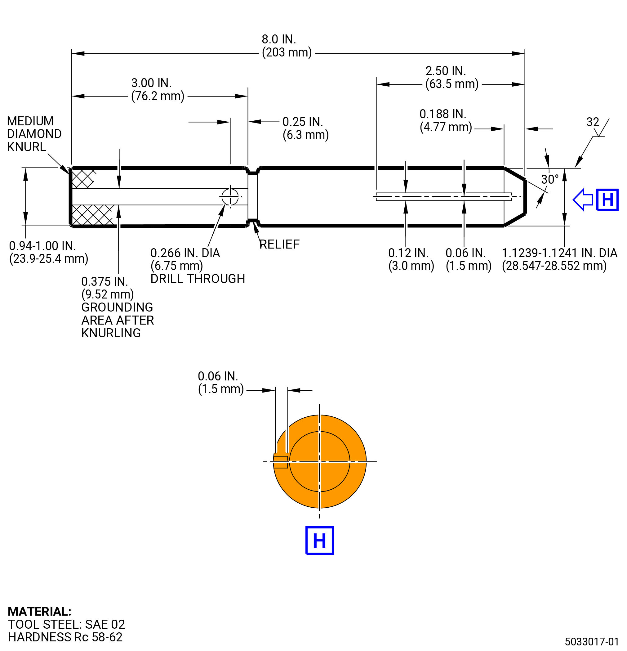
| B. | Do a pin tests inspection. Refer to Figure 203 and do as follows: |
| (1) | A pin of 1.1240 inches (28.549 mm) nominal must pass thru installed bushings (P/N 2327M58P01 for left and right clevis bushings and P/N 2327M58P02 for center clevis bushing) simultaneously and rotate with finger torque. |
| Subtask 72-00-01-220-036 |
| C. | Do a dimensional inspection of the yoke mount. Refer to Figure 204 and as follows: |
| (1) | The distance between the bushing shoulder surface of outer bushings must be 2.925 - 2.955 inches (74.29 - 75.06 mm). |
| (2) | The distance between the bushing shoulder surface of inner bushings must be 1.135 - 1.165 inches (28.83 - 29.59 mm). |
| Subtask 72-00-01-160-002 |
| D. | Clean the yoke mount. Refer to TASK 72-21-06-100-801 (72-21-06, CLEANING 001). |
| NOTE: |
|
| NOTE: |
|
| NOTE: |
|