| GEnx-1B SERVICE BULLETIN - 72-0027 R00 | Revised: 12/02/2011 | |
| SB 72-0027 R00 ENGINE - HPC Assembly - VSV Actuator System (72-30-00) - Introduction of a New Torque Shaft and VSV Linkage Assemblies | Issued: 12/02/2011 | |
| GEnx-1B SERVICE BULLETIN - 72-0027 R00 | Revised: 12/02/2011 | |
| SB 72-0027 R00 ENGINE - HPC Assembly - VSV Actuator System (72-30-00) - Introduction of a New Torque Shaft and VSV Linkage Assemblies | Issued: 12/02/2011 | |
| 1. | PLANNING INFORMATION |
| A. | Effectivity |
|
| This Service Bulletin has been introduced in production to these GEnx-1B engines: |
| • |
|
| These serial numbers are the best available data. |
| The torque shaft P/N 2363M58P01 and P/N 2322M67P02 , and the variable stator vane (VSV) torque shaft linkages (VSV linkage assemblies) P/N 2360M57G01 and P/N 2360M57G02 are affected by this Service Bulletin. |
| B. | Description |
| This Service Bulletin introduces the original certified adjustable torque shaft clevis (adjustable clevis) VSV linkage assemblies P/N 2324M35G05 and P/N 2324M35G06 to the GEnx-1B engine illustrated parts catalog (EIPC) and provides new assembly and disassembly instructions for these early configuration VSV linkage assemblies. Also, this Service Bulletin releases the new VSV linkage assemblies P/N 2360M57G03 and P/N 2360M57G04. |
| C. | Compliance |
| Category 7 |
| GE recommends that you do this Service Bulletin at customer's option. |
| NOTE: |
|
| D. | Concurrent Requirements |
| None. |
| E. | Reason |
| (1) | Objective: |
| To introduce new parts. |
| (2) | Condition: |
| The certified original design of the VSV linkage assembly included a more complicated adjustable clevis, which was also heavier than subsequent designs. The subsequent non-adjustable torque shaft clevis (integral clevis) VSV linkage assembly design was also produced with a complicated manufacturing process. |
| (3) | Cause: |
| The more complicated and heavier adjustable clevis VSV linkage assembly was originally needed in the GEnx development program for VSV system adjustments. The original manufacturing processes were also not optimized for the subsequent integral clevis VSV linkage assembly design. |
| (4) | Improvement: |
| The new VSV linkage assembly maintains the integral clevis design that reduces weight and parts count relative to the original adjustable clevis VSV linkage assembly design with the simplified torque shaft design. Plus, additional manufacturing process improvements have been incorporated into the latest torque shaft design. |
| (5) | Substantiation: |
| Substantiation is by comparative analysis. |
| F. | Approval |
| This Service Bulletin has been reviewed by the FAA and the repair(s) and modification(s) herein comply with the applicable Federal Aviation Regulations and are FAA APPROVED for installation in the model(s) listed in this Service Bulletin. |
| G. | Manpower |
| No additional man-hours are required to comply with this Service Bulletin. |
| H. | Weight and Balance |
| The complete compliance with this Service Bulletin decreases weight by 12.4 lb (5.6 kg) on engines that replace the adjustable clevis VSV linkage assembly with the new integral clevis VSV linkage assembly. |
| I. | References (Use the latest version of these documents) |
| GEK 112851, GEnx-1B Engine Manual (EM) |
| GEK 112862, GEnx-1B Cleaning, Inspection, and Repair Manual (CIR) |
| GEK 112864, GEnx-1B Engine Illustrated Parts Catalog (EIPC) |
| NOTE: |
|
| J. | Publications Affected |
| GEK 112851, GEnx-1B Engine Manual (EM) |
| GEK 112862, GEnx-1B Cleaning, Inspection, and Repair Manual (CIR) |
| GEK 112864, GEnx-1B Engine Illustrated Parts Catalog (EIPC) |
| K. | Interchangeability |
| The old integral clevis VSV linkage assemblies P/N 2360M57G01 and P/N 2360M57G02 are fully interchangeable with the new integral clevis VSV linkage assemblies P/N 2360M57G03 and P/N 2360M57G04, including the forward and aft supports. |
| The original adjustable clevis VSV linkage assemblies P/N 2324M35G05 and P/N 2324M35G06 have qualified interchangeability with the new integral clevis VSV linkage assemblies P/N 2360M57G03 and P/N 2360M57G04 due to the difference in the attachment locations of the forward and aft flange joints. These differences are identified in the accomplishment instructions. |
| L. | Software Accomplishment Summary |
| Not applicable. |
| 2. | MATERIAL INFORMATION |
| A. | Material - Price and Availability |
| (1) | Parts necessary to do this Service Bulletin: |
|
| NOTE: |
|
| (2) | Other Spare Parts: |
| None. |
| (3) | Consumables: |
|
| B. | Industry Support Information |
| None. |
| C. | Configuration Chart |
|
| Operation Codes RE=Replace RM=Remains RW=Rework NP=Not Provisioned |
| Change Codes 2=Two-way Interchangeable. 5=Qualified Interchangeability. Refer to paragraph 1.K., Interchangeability. |
| Support Code B=Old parts will be supplied until all old parts are sold. |
| D. | Parts Disposition |
| None. |
| E. | Tooling - Price and Availability |
| None. |
| 3. | ACCOMPLISHMENT INSTRUCTIONS |
| A. | General |
| (1) | There are three different configurations of the VSV linkage assemblies (01-010 and 01-130, 72-30-00, Figure 1): |
| (a) | The VSV linkage assembly configuration 1 (01-010 and 01-130) contains a torque shaft which includes bolted on adjustable clevis. |
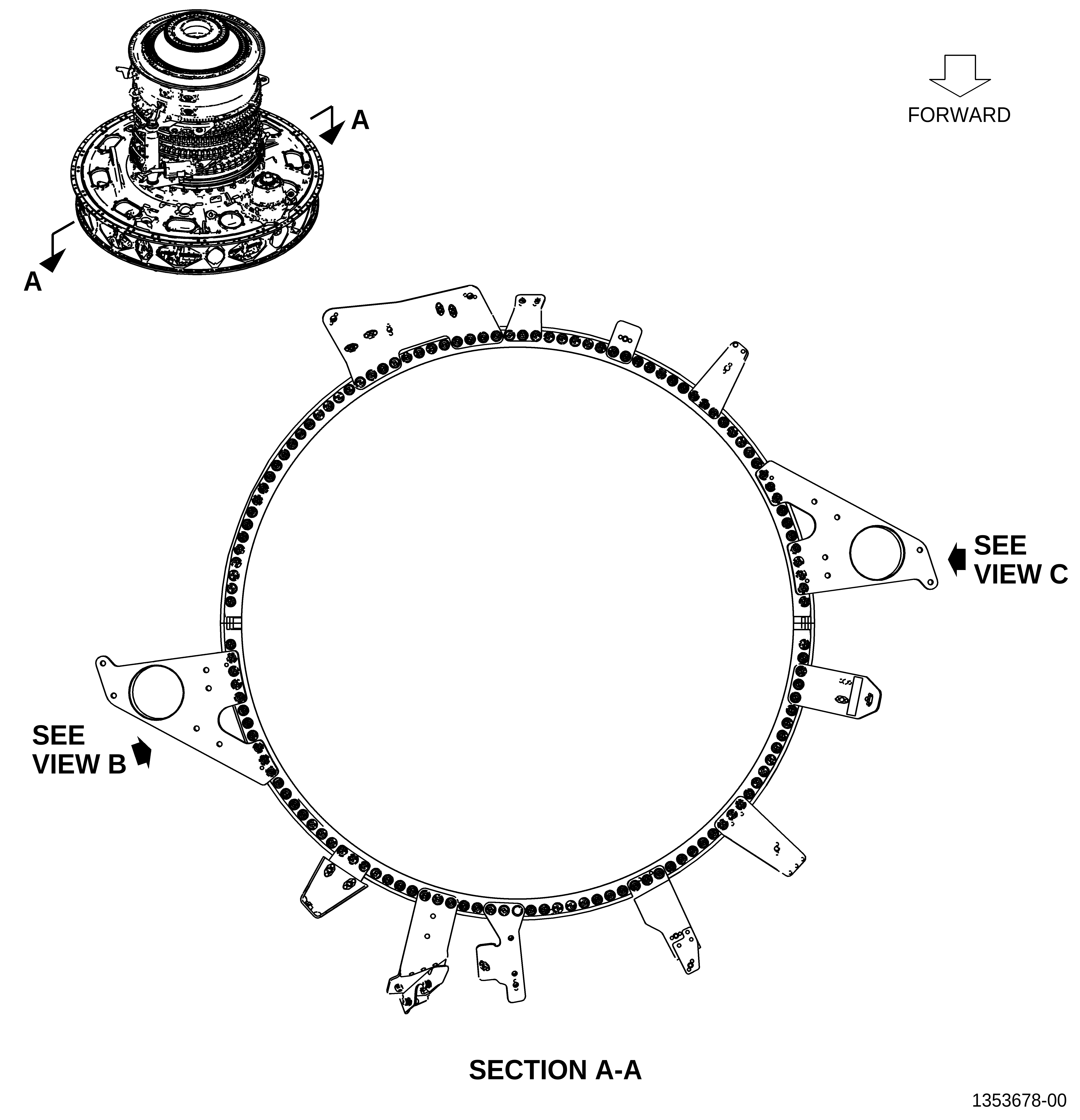
| (b) | The VSV linkage assembly configuration 2 (01-010 and 01-130) contains a torque shaft which incorporates an integral clevis. Also, the forward supports (01-065 and 01-0185, 72-30-00, Figure 2) and the aft supports (01-060 and 01-0180, 72-30-00, Figure 3) have different attachment locations than the VSV linkage assembly configuration 1. |
| (c) | The VSV linkage assembly configuration 3 (01-010 and 01-130) contains a torque shaft which is cast to a near final shape, has a slightly longer cylinder section, and slightly thicker integral clevis arms than the VSV linkage assembly configuration 2. The same forward supports (01-065 and 01-0185, 72-30-00, Figure 2) and the aft supports (01-060 and 01-0180, 72-30-00, Figure 3) are also used as VSV linkage assembly configuration 2. |
| B. | Removal of the VSV linkage assembly configuration 1 |
| (1) | Removal instructions for the VSV linkage assembly configuration 1 have not changed. Refer to the GEnx-1B EM, 72-30-00, DISASSEMBLY 001. |
| C. | Removal of the VSV linkage assembly configuration 2 or 3 |
| (1) | Remove the left and right VSV actuators. Refer to the GEnx-1B EM, 72-30-00, DISASSEMBLY 001, Subtask 72-30-00-030-072. |
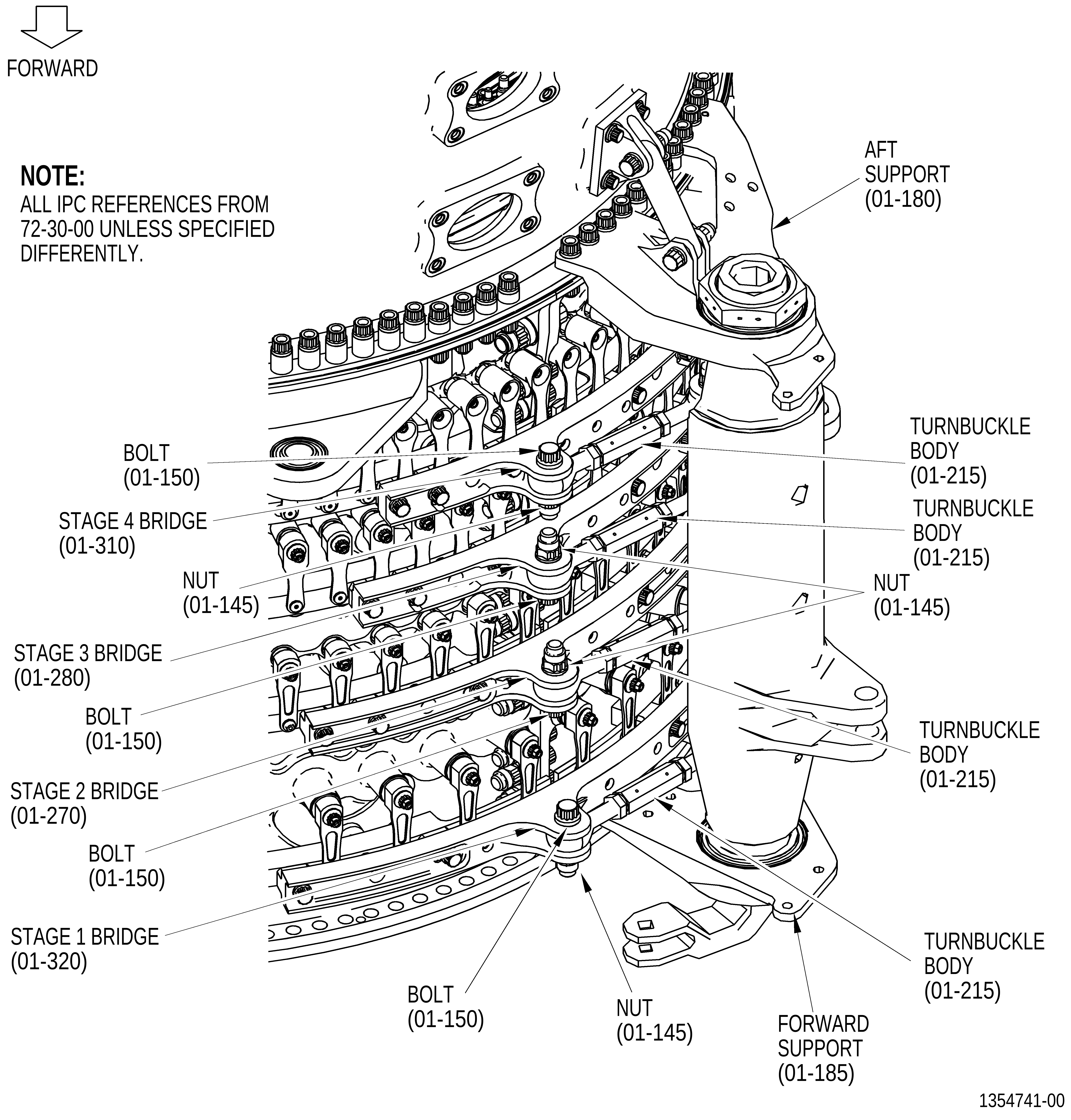
| (2) | Remove the four turnbuckle bodies (01-215, 72-30-00, Figure 3) at the 3:00 o'clock position aft looking forward (ALF) from the stages 1-4 bridges (01-320, 01-270, 01-280, and 01-310) as follows: |
| (a) | Remove the four self-locking nuts (nuts) (01-145) from the four bolts (01-150). |
| (b) | Remove the four bolts (01-150). |
| (c) | Remove the four turnbuckle bodies (01-215) from the stages 1-4 bridges (01-320, 01-270, 01-280, and 01-310). |
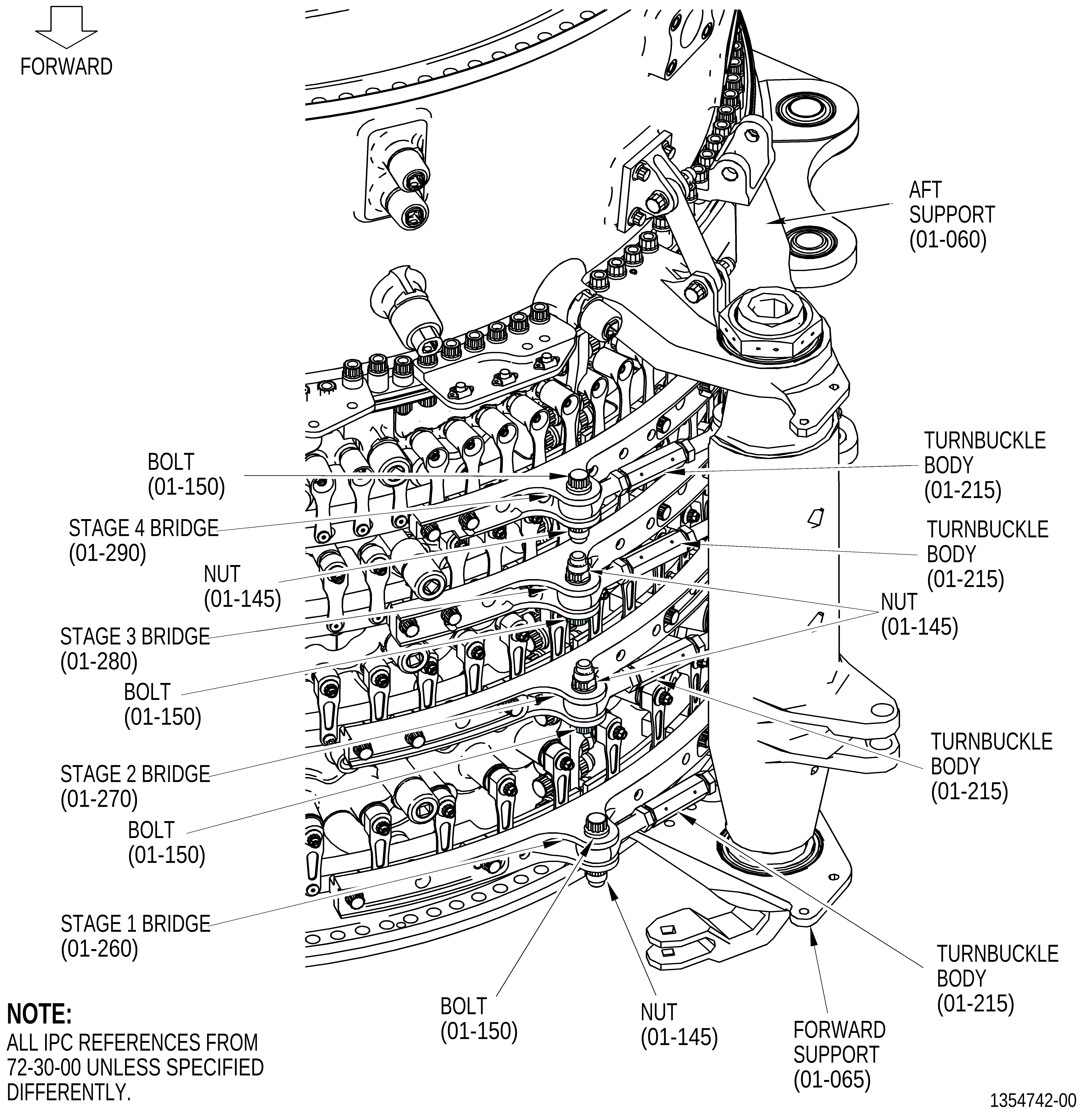
| (3) | Remove the four turnbuckle bodies (01-215, 72-30-00, Figure 4) at the 9:00 o'clock position ALF from the stages 1-4 bridges (01-260, 01-270, 01-280, and 01-290) as follows: |
| (a) | Remove the four nuts (01-145) from the four bolts (01-150). |
| (b) | Remove the four bolts (01-150). |
| (c) | Remove the four turnbuckle bodies (01-215) from the stages 1-4 bridges (01-260, 01-270, 01-280, and 01-290). |
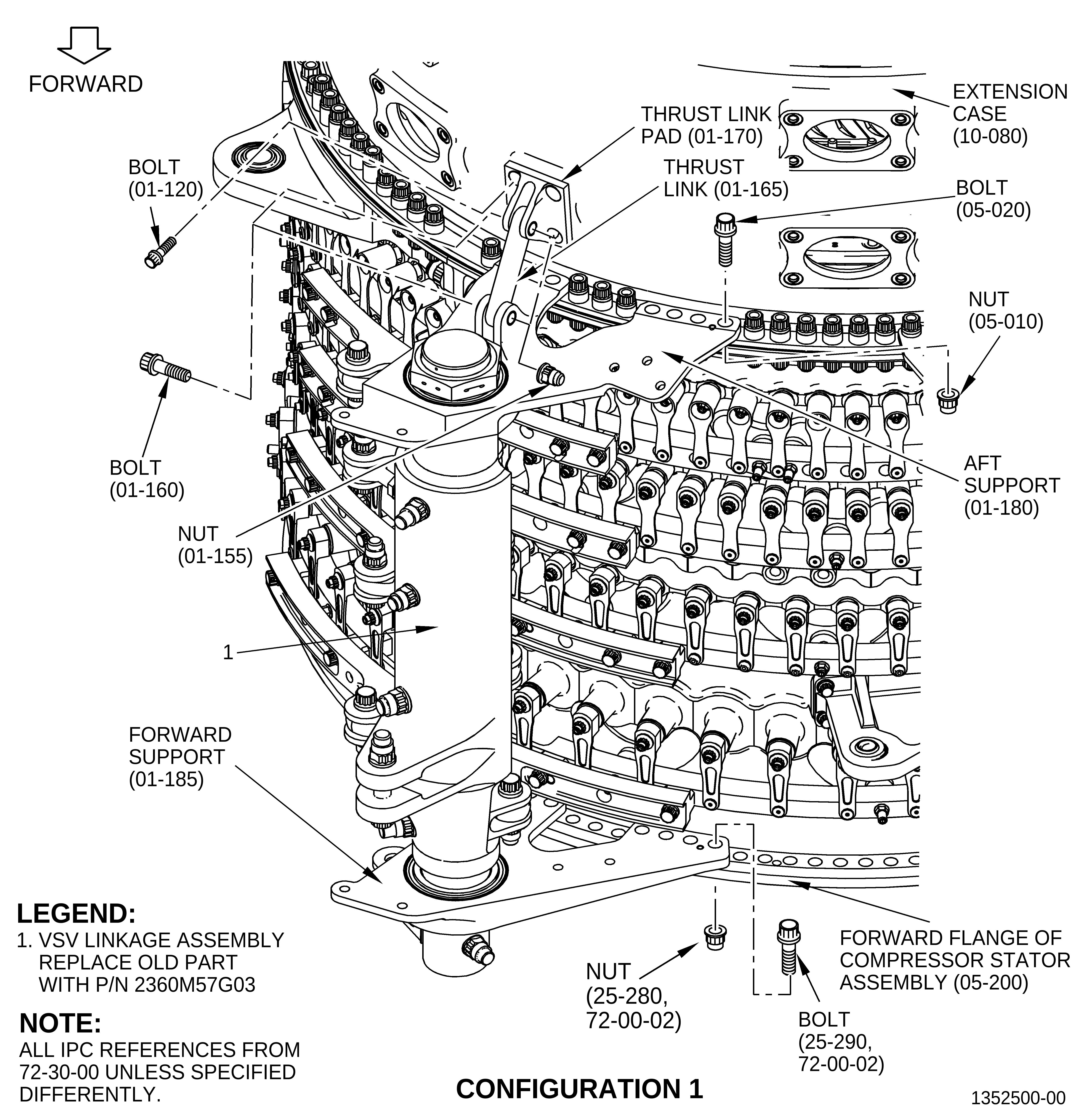
| (4) | Remove the VSV linkage assembly (1, Figure 5) at the 3:00 o'clock position ALF as follows: |
| (a) | Remove the two nuts (01-155, 72-30-00) and the two bolts (01-160) from the thrust link (01-165). |
| (b) | Remove the thrust link (01-165). |
| (c) | Remove the four bolts (01-120) from the thrust link pad (01-170). |
| (d) | Remove the thrust link pad (01-170) from the extension case (10-080). |
| (e) | Remove the seven nuts (25-280, 72-00-02) and seven bolts (25-290) that attach the forward support (01-185, 72-30-00) to the compressor stator assembly (05-200). |
| (f) | Remove the eight bolts (05-020) and the eight nuts (05-010) that attach the aft support (01-180) to the extension case (10-080) and compressor stator assembly (05-200). |
| (g) | Remove the VSV linkage assembly (1) from the compressor stator assembly (05-200) and extension case (10-080). |
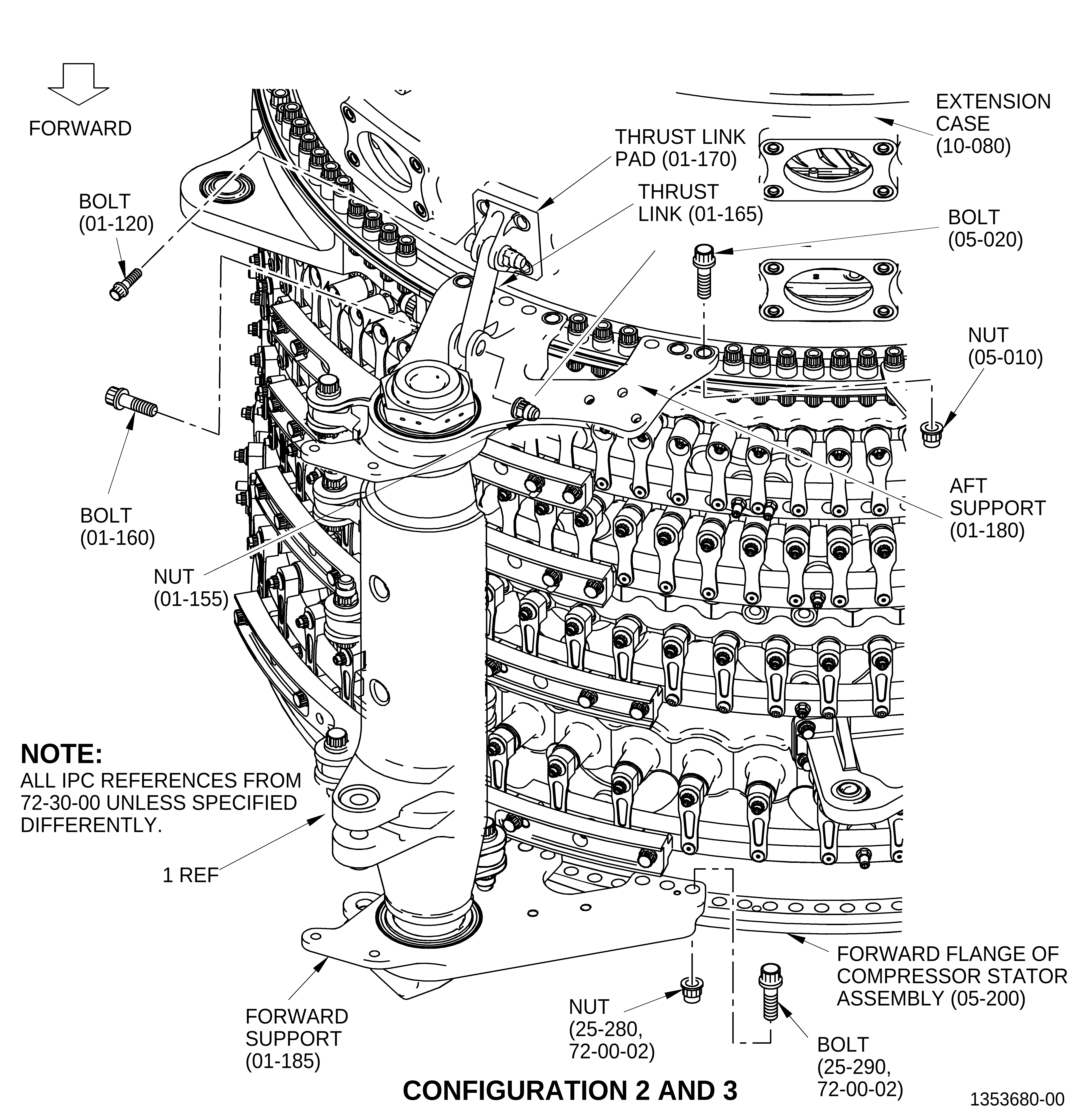
| (5) | Remove the VSV linkage assembly (1, Figure 6) at the 9:00 o'clock position ALF as follows: |
| (a) | Remove the two nuts (01-135, 72-30-00) and two bolts (01-140) from the thrust link (01-145). |
| (b) | Remove the thrust link (01-145). |
| (c) | Remove the four bolts (01-120) from the thrust link pad (01-150). |
| (d) | Remove the thrust link pad (01-150) from the extension case (10-080). |
| (e) | Remove the seven nuts (25-280, 72-00-02) and seven bolts (25-290) that attach the forward support (01-165, 72-30-00) to the compressor stator assembly (05-200). |
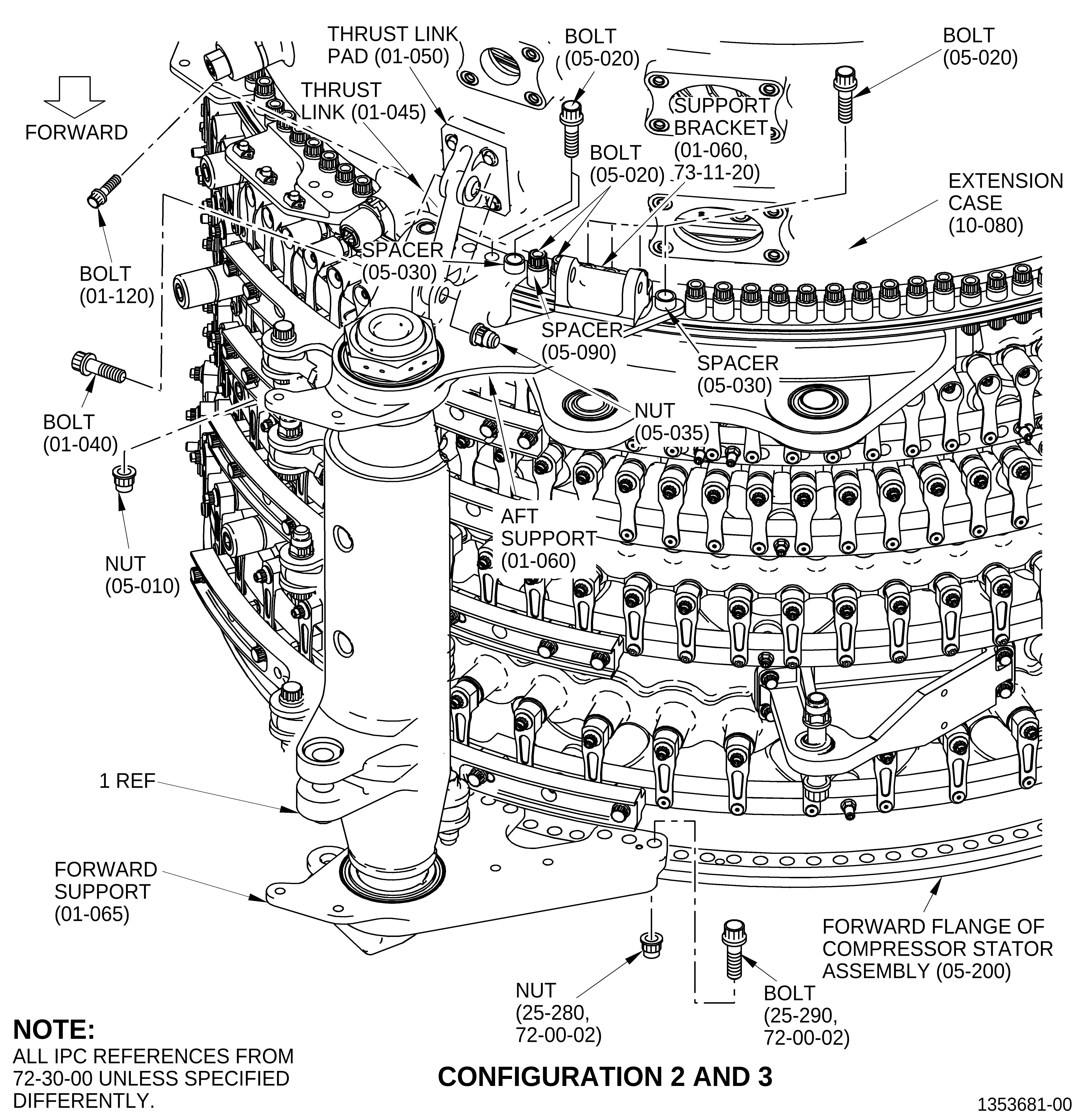
| (f) | Remove the eight bolts (05-020), four nuts (05-010), and two spacers (05-030) that attach the aft support (01-060) to the extension case (10-080) and compressor stator assembly (05-200). |
| (g) | Remove the remaining bolt (05-020) and spacer (05-030) that attach the support bracket (01-060) to the aft extension case and the compressor stator assembly (05-200). |
| (h) | Remove the VSV linkage assembly (1) from the compressor stator assembly (05-200) and extension case (10-080). |
| D. | Installation of the VSV linkage assembly configuration 1 |
| (1) | Installation instructions for the VSV linkage assembly configuration 1 have not changed. Refer to the GEnx-1B EM, 72-30-00, ASSEMBLY 002. |
| E. | Installation of the VSV linkage assembly configuration 2 or 3 |
| (1) | Install the VSV linkage assembly configuration 2 or 3 at the 3:00 o'clock position ALF (01-130, 72-30-00, Figure 1) on the aft face of the extension case (10-080, 72-30-00, Figure 5) forward flange and on the aft face of the forward flange of the compressor stator assembly (05-200) as follows: |
| NOTE: |
|
| NOTE: |
|
| (a) | Align the dowel pins in the aft support (01-180) with the holes located near to the boltholes No. 21 and No. 31 on the aft face of the extension case (10-080) forward flange. |
| (b) | Align the dowel pins in the forward support (01-185) with the holes on the aft face of the forward flange of the compressor stator assembly (05-200). |
| (c) | Put the VSV linkage assembly (1) on the aft face of the extension case (10-080) forward flange and the aft face of the forward flange of the compressor assembly (05-200). |
| (d) | Make sure that the boltholes in the aft support (01-180) are aligned with the boltholes No. 21 thru No. 23, and the boltholes No. 27 thru No. 31 on the aft face of the extension case (10-080) forward flange. |
| (e) | Apply a thin layer of C02-058 lubricant to the threads and the pressure faces of eight bolts (05-020) and eight self-locking nuts (05-010). |
| (f) | Attach the aft support (01-180) with the eight bolts (05-020) and the eight nuts (05-010). Do not tighten the eight nuts (05-010). |
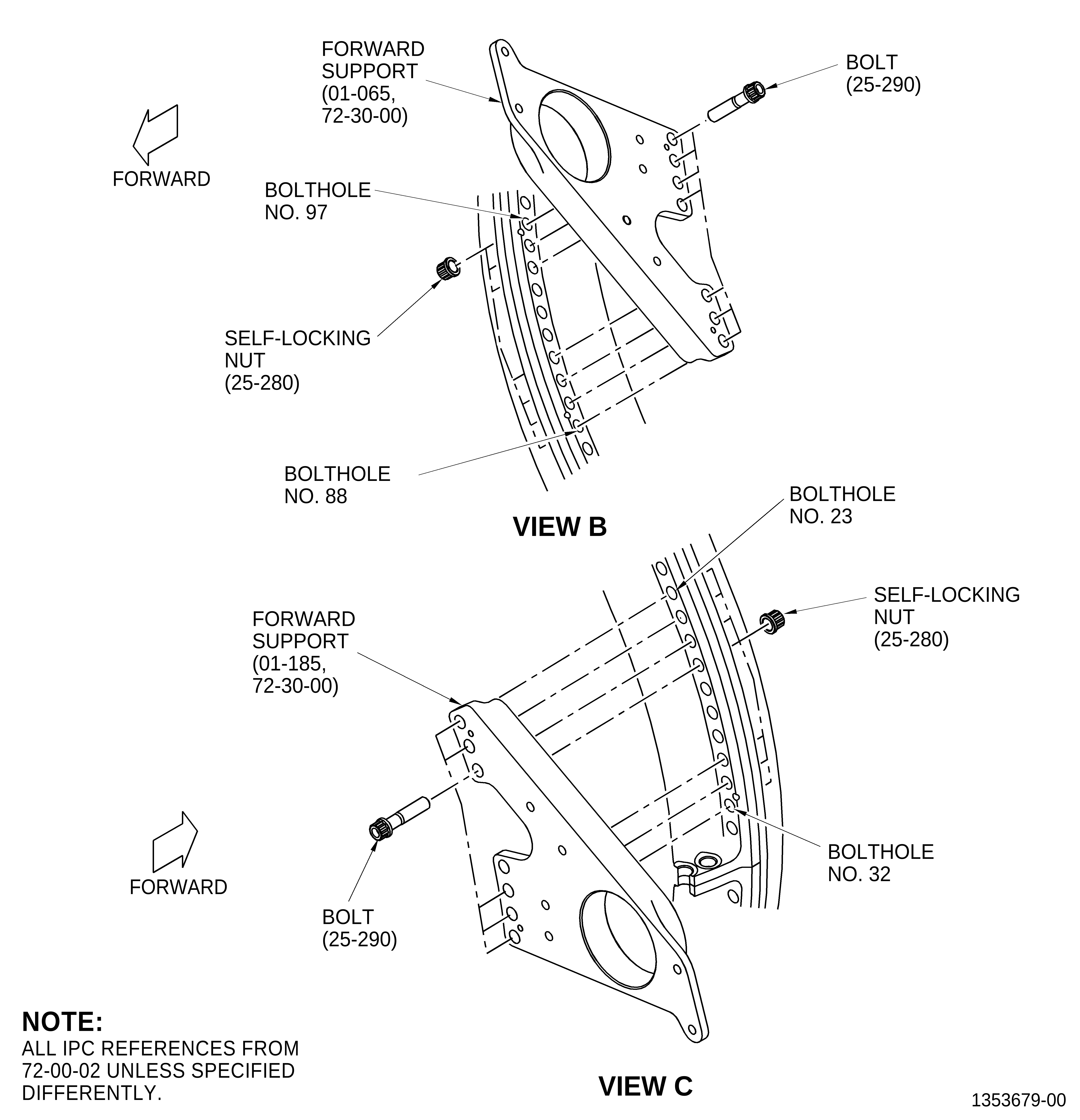
| (2) | Install the forward support (01-185, Figure 2) on the aft face of the forward flange of the compressor stator assembly (05-200). |
| (3) | Apply a thin layer of C02-058 lubricant to the threads and the pressure faces of seven bolts (25-290, 72-00-02) and seven self-locking nuts (25-280). |
| (4) | Put the seven bolts (25-290) and seven nuts (25-280) in the boltholes No. 23 thru No. 25 and No. 29 thru No.32 with the bolthead aft. |
| NOTE: |
|
| (5) | Torque the seven nuts (25-280) to 276-324 lb in. (31.2-36.6 N.m) in a alternating pattern to seat the forward support (01-185, 72-30-00) on the flange. |
| (6) | Final torque the seven nuts (25-280, 72-00-02) to 368-432 lb in. (41.6-48.8 N.m). |
| (7) | Torque the eight nuts (05-010, 72-30-00, Figure 5) on the aft support (01-180) to 276-324 lb in. (31.2-36.6 N.m) in a alternating pattern to seat the aft support (01-180) on the flange. |
| (8) | Final torque the eight nuts (05-010) on the aft support (01-180) to 368-432 lb in. (41.6-48.8 N.m). |
| (9) | Attach the thrust link pad (01-170, Figure 5) of aft support (01-180) to the extension case (10-080) near to the 3:00 o'clock as follows: |
| (a) | Apply a thin layer of C02-058 lubricant to the threads and the pressure faces of four bolts (01-120). |
| (b) | Put the thrust link pad (01-170) on the pad boss on the extension case (10-080) and attach it with the four bolts (01-120). |
| (c) | Torque the four bolts (01-120) to 106-124 lb in. (12.0-14.0 N.m). |
| (10) | Install the VSV linkage assembly configuration 2 or 3 at the 9:00 o'clock position ALF (01-010, 72-30-00, Figure 1) on the aft face of the extension case (10-080, 72-30-00, Figure 6) forward flange and on the aft face of the forward flange of the compressor stator assembly (05-200) as follows: |
| NOTE: |
|
| NOTE: |
|
| (a) | Align the dowel pins in the aft support (01-060, 72-30-00, Figure 6) with the holes located near to the boltholes No. 83 and No. 93 on the aft face of the extension case (10-080) forward flange. |
| (b) | Align the dowel pins in the forward support (01-065) with the holes on the aft face of the forward flange of the compressor stator assembly (05-200). |
| (c) | Put the VSV linkage assembly (1) on the aft face of the extension case (10-080) forward flange and the aft face of the forward flange of the compressor assembly (05-200). |
| (d) | Make sure that the boltholes in the aft support (01-060) are aligned with the boltholes No. 83 thru No. 85 and the boltholes No. 89 thru No. 93 on the aft face of the extension case (10-080) forward flange. |
| (e) | Apply a thin layer of C02-058 lubricant to the threads and the pressure faces of six bolts (05-020) and four self-locking nuts (05-010). |
| (f) | Attach the aft support (01-060) with the four bolts (05-020) and four nuts (05-010) at boltholes No. 90 thru No. 93 and two bolts (05-020) with two spacers (05-030) below the bolthead at boltholes No. 83 and No. 89. Do not tighten the nuts (05-010) or the bolts (05-020). |
| (g) | Install the support bracket (01-060, 73-11-20) on the aft support (01-060, 72-30-00) at boltholes No. 84 thru No. 86. |
| (h) | Apply a thin layer of C02-058 lubricant to the threads and the pressure faces of three bolts (05-020). |
| (i) | Attach the support bracket (01-060, 73-11-20) with the three bolts (05-020, 72-30-00) and one spacer (05-030) located below the aft support (01-060) at bolthole No. 86. Do not tighten the bolts (05-020). |
| (11) | Install the forward support (01-065, Figure 2) on the aft face of the forward flange of the compressor stator assembly (05-200). |
| (12) | Apply a thin layer of C02-058 lubricant to the threads and the pressure faces of seven bolts (25-290, 72-00-02) and seven self-locking nuts (25-280). |
| (13) | Put the seven bolts (25-290) and seven nuts (25-280) in the boltholes No. 88 thru 90 and No. 94 thru No. 97 with the bolthead aft. |
| NOTE: |
|
| (14) | Torque the seven nuts (25-280) on the forward support (01-065, 72-30-00) to 276-324 lb in. (31.2-36.6 N.m) in a alternating pattern to seat the forward support (01-065) on the flange. |
| (15) | Final torque the seven nuts (25-280, 72-00-02) to 368-432 lb in. (41.6-48.8 N.m). |
| (16) | Torque the four bolts (05-020, 72-30-00, Figure 6) and four nuts (05-010) on the aft support (01-060) to 276-324 lb in. (31.2-36.6 N.m) in a alternating pattern to seat the aft support (01-060) on the flange. |
| (17) | Final torque the four bolts (05-020) and four nuts (05-010) on the aft support (01-060) to 368-432 lb in. (41.6-48.8 N.m). |
| (18) | Make sure all bolts for the support bracket (01-060, 73-11-20) have torque applied. |
| NOTE: |
|
| (19) | Attach the thrust link pad (01-050, 72-30-00) of aft support (01-060) to the extension case (10-080) near to the 9:00 o'clock position ALF as follows: |
| (a) | Apply a thin layer of C02-058 lubricant to the threads and the pressure faces of four bolts (01-120). |
| (b) | Put the thrust link pad (01-050) on the pad boss on the extension case (10-080) and attach it with the four bolts (01-120). |
| (c) | Torque the four bolts (01-120) to 106-124 lb in. (12.0-14.0 N.m). |