| GEnx-1B SERVICE BULLETIN - 72-0048 R01 | Revised: 02/18/2013 | |
| SB 72-0048 R01 ENGINE - Turbine Center Frame Assembly - Air Adapters and Tubes (72-54-00) - Introduction of New Adapter Cap Deflectors | Issued: 10/21/2011 | |
| GEnx-1B SERVICE BULLETIN - 72-0048 R01 | Revised: 02/18/2013 | |
| SB 72-0048 R01 ENGINE - Turbine Center Frame Assembly - Air Adapters and Tubes (72-54-00) - Introduction of New Adapter Cap Deflectors | Issued: 10/21/2011 | |
| TRANSMITTAL INFORMATION |
| REVISION 1 TO SERVICE BULLETIN 72-0048 |
| Revision 1 is issued to update paragraph 2., MATERIAL INFORMATION and paragraph 3., ACCOMPLISHMENT INSTRUCTIONS. |
| The original was issued October 21, 2011. Revision bars in the left margin identify changes. |
| 1. | PLANNING INFORMATION |
| A. | Effectivity |
|
| This Service Bulletin is applicable to these GEnx-1B engines: |
| • |
|
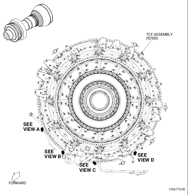
| B. | Description |
| This Service Bulletin introduces the new deflectors P/Ns 2474M51P01, 2474M52P01, 2474M51P02 and hose clamps P/N 1519M13P11. |
| C. | Compliance |
| Category 9 |
| Information Only. |
| NOTE: |
|
| D. | Concurrent Requirements |
| None. |
| E. | Reason |
| (1) | Objective: |
| To improve reliability. |
| (2) | Condition: |
| During GEnx-1B ETOPS certification engine testing on the turbine center frame (TCF) strut 5 oil supply tube, the outer piston ring became dislodged resulting in TCF purge air leaking from the end of the air adapter. The leaking air impinged on the thrust reverser insulation blanket resulting in non-serviceable damage. |
| (3) | Cause: |
| The piston ring has insufficient engagement with the piston ring groove due to wear on the shoulders of the tube fitting, resulting from side loading of the tube by the external tubes. |
| (4) | Improvement: |
| The deflectors will disperse the air leaking from the end of the adapter caps diverting it back towards the engine. This will decrease the damage to the thrust reverser. |
| (5) | Substantiation: |
| Substantiation is by analysis and comparative analysis. |
| F. | Approval |
| This Service Bulletin has been reviewed by the FAA and the repair(s) and modification(s) herein comply with the applicable Federal Aviation Regulations and are FAA APPROVED for installation in the model(s) listed in this Service Bulletin. |
| G. | Manpower |
| After you get access to the engine, you will need approximately 3.0 man-hours for each engine or component. |
| H. | Weight and Balance |
| The complete compliance with this Service Bulletin increases weight by 0.6 lb (0.27 kg). |
| I. | References (Use the latest version of these documents) |
| GEK 112851, GEnx-1B Engine Manual (EM) |
| GEK 112866, GEnx-1B Illustrated Tool and Equipment Manual (ITEM) |
| NOTE: |
|
| J. | Publications Affected |
| GEK 112851, GEnx-1B Engine Manual (EM) |
| GEK 112866, GEnx-1B Illustrated Tool and Equipment Manual (ITEM) |
| K. | Interchangeability |
| Qualified interchangeability. |
| L. | Software Accomplishment Summary |
| Not applicable. |
| 2. | MATERIAL INFORMATION |
| A. | Material - Price and Availability |
| (1) | Parts necessary to do this Service Bulletin: |
|
| NOTE: |
|
| (2) | Other Spare Parts: |
| None. |
| (3) | Consumables: |
| None. |
| B. | Industry Support Information |
| Contact your Customer Support Manager (CSM) for industry Support information. |
| C. | Configuration Chart |
|
| Operation Codes AD=Add RM=Remains |
| Change Code 5=Qualified interchangeability. Refer to paragraph 1.K., Interchangeability. |
| Support Codes None. |
| D. | Parts Disposition |
| None. |
| E. | Tooling - Price and Availability |
| None. |
| 3. | ACCOMPLISHMENT INSTRUCTIONS |
| A. | Removal of the Deflectors |
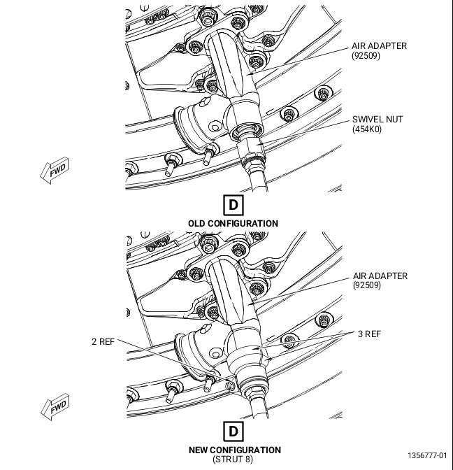
| (1) | Remove the deflectors (3, Figure 1, Sheet 5) and hose clamp (2) at the strut 8 as follows: |
| (a) | Remove the hose clamp (2) that secures the two deflectors (3). |
| (b) | Remove the two deflectors (3) from the swivel nut (454K0) and the air adapter (92509). |
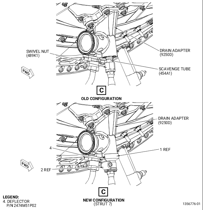
| (2) | Remove the deflectors (1 and 4, Figure 1, Sheet 4) and hose clamp (2) at the strut 7 as follows: |
| (a) | Remove the hose clamp (2) that secures the two deflectors (1 and 4). |
| (b) | Remove the two deflectors (1 and 4) from the swivel nut (489K1) and the drain adapter (9250D). |
| (3) | Remove the deflectors (3, Figure 1, Sheet 3) and hose clamp (2) at the strut 6 as follows: |
| (a) | Remove the hose clamp (2) that secures the two deflectors (3). |
| (b) | Remove the two deflectors (3) from the swivel nut (454K0) and the air adapter (9250C). |
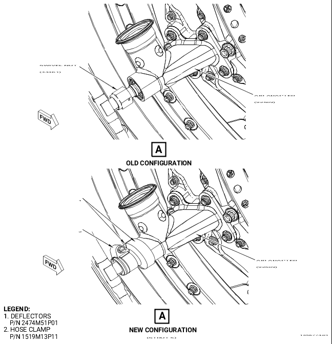
| (4) | Remove the deflectors (1, Figure 1, Sheet 2) and hose clamp (2) at the strut 5 as follows: |
| (a) | Remove the hose clamp (2) that secures the two deflectors (1). |
| (b) | Remove the two deflectors (1) from the swivel nut (443K1) and the air adapter (92509). |
| B. | Installation of the Deflectors |
| (1) | Install two deflectors (1, Figure 1, Sheet 2) and a hose clamp (2) at the strut 5 as follows: |
| (a) | Install the two deflectors (1) around the swivel nut (443K1) and the air adapter (92509). Make sure that the corners of the swivel nut wrenching feature edges do not line up with the gaps between the two deflectors (1). |
| (b) | Secure the deflectors (1) with a hose clamp (2). Torque the hose clamp (2) to 32-38 lb in. (3.6-4.3 Nm). |
| (c) | Remove any excess in length of the hose clamp (2) so no more than 1.00 inch (25.4 mm) is exposed between the house clamp (2) and the screw. No burrs are permitted. |
| (2) | Install two deflectors (3, Figure 1, Sheet 3) and a hose clamp (2) at the strut 6 as follows: |
| (a) | Install the two deflectors (3) around the swivel nut (454K0) and the air adapter (9250C). Make sure that the corners of the swivel nut wrenching feature do not line up with the gaps between the deflectors (3). |
| (b) | Secure the deflectors (3) with a hose clamp (2). Torque the hose clamp (2) to 32-38 lb in. (3.6-4.3 Nm). |
| (c) | Remove any excess in length of the hose clamp (2), so no more than 1.00 inch (25.4 mm) is exposed between the house clamp (2) and the screw. No burrs are permitted. |
| (3) | Install a deflector (1, Figure 1, Sheet 4), a deflector (4), and a hose clamp (2) at the strut 7 as follows: |
| (a) | Install the deflectors (1 and 4) around the swivel nut (489K1) and the drain adapter (9250D). Make sure that the corners of the swivel nut wrenching feature do not line up with the gaps between the deflectors (1 and 4). |
| NOTE: |
|
| (b) | Secure the deflectors (1 and 4) with a hose clamp (2). Torque the hose clamp (2) to 32-38 lb in. (3.6-4.3 Nm). |
| (c) | Remove any excess in length of the hose clamp (2), so no more than 1.00 inch (25.4 mm) is exposed between the house clamp (2) and the screw. No burrs are permitted. |
| (4) | Install two deflectors (3, Figure 1, Sheet 5) and a hose clamp (2) at the strut 8 as follows: |
| (a) | Install the two deflectors (3) around the swivel nut (454K0) and the air adapter (92509). Make sure that the corners of the swivel nut wrenching feature do not line up with the gaps between the two deflectors (1). |
| (b) | Secure the two deflectors (3) with a hose clamp (2). Torque the hose clamp (2) to 32-38 lb in. (3.6-4.3 Nm). |
| (c) | Remove any excess in length of the hose clamp (2), so no more than 1.00 inch (25.4 mm) is exposed between the house clamp (2) and the screw. No burrs are permitted. |