| GEnx-1B SERVICE BULLETIN - 72-0054 R04 | Revised: 12/28/2018 | |
| SB 72-0054 R04 ENGINE - Propulsor Module Assembly (72-00-00) - Introduction of New B-Sump Drain Hardware | Issued: 12/19/2011 | |
| GEnx-1B SERVICE BULLETIN - 72-0054 R04 | Revised: 12/28/2018 | |
| SB 72-0054 R04 ENGINE - Propulsor Module Assembly (72-00-00) - Introduction of New B-Sump Drain Hardware | Issued: 12/19/2011 | |
| GE Designated: -CONFIDENTIAL- | |
| The information contained in this document is GE proprietary information and is disclosed in confidence. It is the property of GE and shall not be used, disclosed to others or reproduced without the express written consent of GE, including, but without limitation, it is not to be used in the creation, manufacture, development, or derivation of any repairs, modifications, spare parts, designs, or configuration changes or to obtain FAA or any other government or regulatory approval to do so. If consent is given for reproduction in whole or in part, this notice and the notice set forth on each page of this document shall appear in any such reproduction in whole or part. | |
| This technical data is considered subject to the Export Administration Regulations (EAR) pursuant to 15 CFR Parts 730-774. Transfer of this data by any means to a Non-U.S. Person, whether in the United States or abroad, without the proper U.S. Government authorization (e.g., License, exemption, NLR, etc.), is strictly prohibited. | |
| Copyright (2018) General Electric Company, U.S.A. |
| TRANSMITTAL INFORMATION |
| REVISION 4 TO SERVICE BULLETIN 72-0054 |
| Revision 4 is issued to update paragraphs 1., PLANNING INFORMATION, 2., MATERIAL INFORMATION, and 3., ACCOMPLISHMENT INSTRUCTIONS. |
| Revision 3 was issued May 10, 2013. Revision 2 was issued December 03, 2012. Revision 1 was issued February 13, 2012. The original was issued December 19, 2011. Revision bars in the left margin identify changes. |
| 1. | PLANNING INFORMATION |
| A. | Effectivity |
|
| This Service Bulletin is applicable to these GEnx-1B engines: |
| • |
|
| These serial numbers are the best available data. |
| The B-sump drain hardware is affected by this Service Bulletin. |
| B. | Description |
| This Service Bulletin releases a new B-sump drain hardware. |
| C. | Compliance |
| Category 9 |
| Information only. |
| Impact F |
| Implement as deemed necessary per the Service Bulletin Category. |
| D. | Concurrent Requirements |
| None. |
| E. | Reason |
| (1) | Objective: |
| To introduce new parts. |
| (2) | Condition: |
| Possible contact between the B-sump drain hardware and the thrust reverser aft latches occurs when the thrust reverser doors are opened. |
| (3) | Cause: |
| The B-sump drain hardware and thrust reverser aft latches were designed separately without considering the possible interference or the potential for contact between hardware. |
| (4) | Improvement: |
| The new B-sump drain hardware routing is less likely to contact the surrounding hardware, which improves hardware durability. |
| (5) | Substantiation: |
| Substantiation is by analysis and comparative analysis. |
| F. | Approval |
| This Service Bulletin has been reviewed by the FAA and the repair(s) and modification(s) herein comply with the applicable Federal Aviation Regulations and are FAA APPROVED for installation in the model(s) listed in this Service Bulletin. |
| G. | Manpower |
| No additional man-hours are required to comply with this Service Bulletin. |
| H. | Weight and Balance |
| The complete compliance with this Service Bulletin increases weight by 1.35 lb (0.61 kg). |
| I. | References (Use the latest version of these documents) |
| GEK 112851, GEnx-1B Engine Manual (EM) |
| GEK 112862, GEnx-1B Cleaning, Inspection, and Repair Manual (CIR) |
| GEK 112864, GEnx-1B Engine Illustrated Parts Catalog (EIPC) |
| NOTE: |
|
| J. | Publications Affected |
| GEK 112851, GEnx-1B Engine Manual (EM) |
| GEK 112862, GEnx-1B Cleaning, Inspection, and Repair Manual (CIR) |
| GEK 112864, GEnx-1B Engine Illustrated Parts Catalog (EIPC) |
| K. | Interchangeability |
| Qualified interchangeability. |
| L. | Software Accomplishment Summary |
| Not applicable. |
| 2. | MATERIAL INFORMATION |
| A. | Material - Price and Availability |
| (1) | Parts necessary to do this Service Bulletin: |
|
| *Part not supplied by GE Engine Services Distribution L.L.C. Procure through local purchase. |
| **Part not supplied by GE Engine Services Distribution L.L.C. To procure parts, contact the following: |
| Elano Corp. 2455 Dayton-Xenia Rd. Dayton, OH 45434-7199 U.S.A. |
| NP = Not Provisioned |
| NOTE: |
|
| (2) | Other Spare Parts: |
| None. |
| (3) | Consumables: |
|
| B. | Industry Support Information |
| None. |
| C. | Configuration Chart |
|
| Operation Codes AD=Add DE=Delete QTC=Quantity Change RE=Replace RM=Remains |
| Change Code 5=Qualified interchangeability. Refer to paragraph 1.K., Interchangeability. |
| Support Codes A=Old parts will no longer be supplied. E=Old parts will be supplied, and can be used at other engine locations. |
| D. | Parts Disposition |
| Discard old parts. |
| E. | Tooling - Price and Availability |
| None. |
| 3. | ACCOMPLISHMENT INSTRUCTIONS |
| A. | Removal |
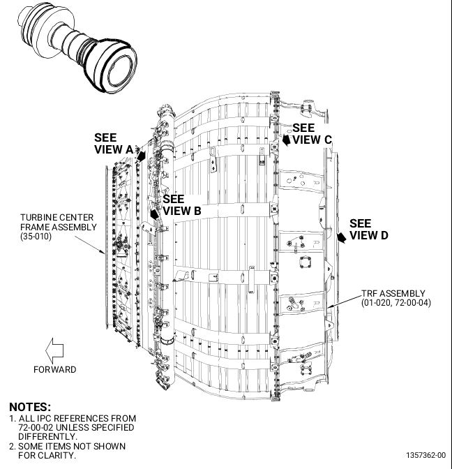
| (1) | Loosen the W30 harness (01-010, 73-21-66) and W31 harness (05-010) from the drain support bracket (1, Figure 1). Refer to the GEnx-1B EM, 72-00-02, DISASSEMBLY 001. |
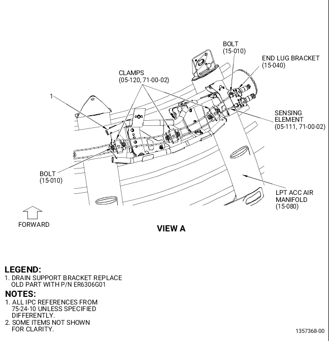
| (2) | Loosen the sensing element (05-111, 71-00-02, Figure 1) from the drain support bracket (1) as follows: |
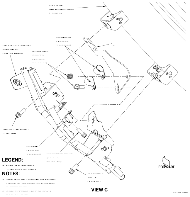
| (a) | Remove the double hex bolts (bolts) (15-010, 75-24-10) that attach the clamps (05-120, 71-00-02) and end lug bracket (15-040, 75-24-10) to the drain support bracket (1). |
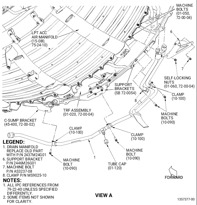
| (3) | Remove the drain manifold (1, Figure 2) from the engine. Refer to the GEnx-1B EM, 72-00-02, DISASSEMBLY 002. |
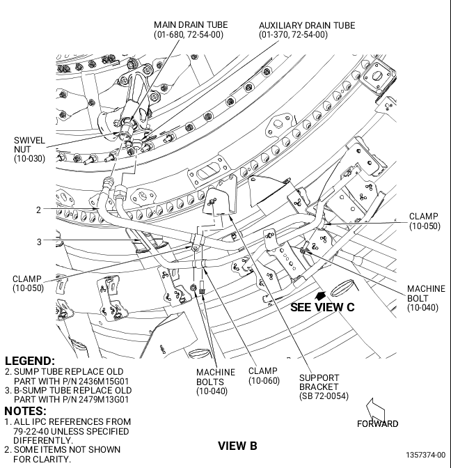
| (4) | Remove the sump tube (2, Figure 2) and B-sump tube (3) from the engine. Refer to the GEnx-1B EM, 72- 00-02, DISASSEMBLY 002. |
| (5) | Remove the drain support bracket (1, Figure 1) and drain bracket (4, Figure 2) from the engine. Refer to the GEnx-1B EM, 72-00-02, DISASSEMBLY 002. |
| B. | Installation |
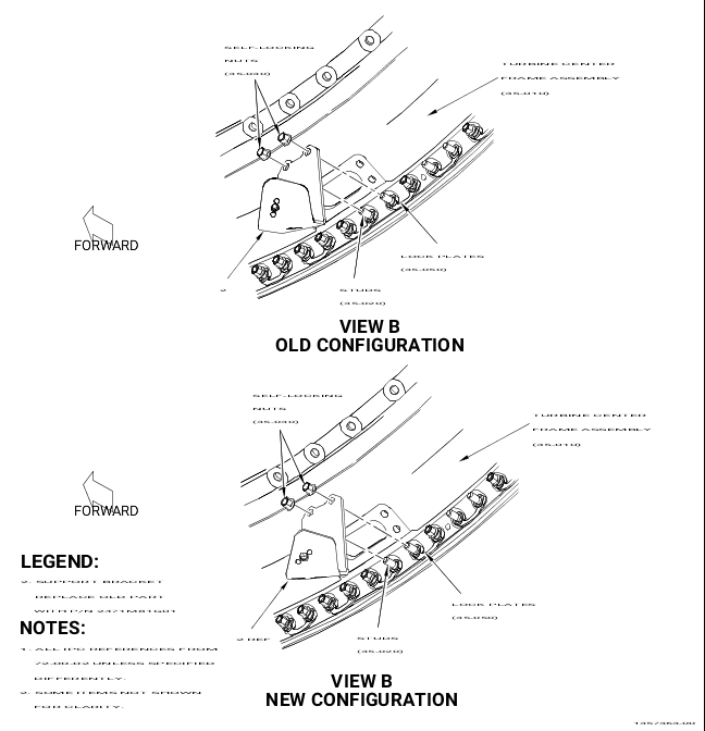
| (1) | Replace the drain support bracket (2, Figure 1) as follows: |
| (a) | Remove the two self-locking nuts (35-030, 72-00-02) that attach the drain support bracket (2) to the self-locking spl studs (studs) (35-020). |
| (b) | Remove the drain support bracket (2) from the engine. Do not remove the two LPT lock plates (lock plates) (35-050). |
| WARNING: |
|
| (c) | Apply engine oil (C02-019) to the threads of the studs (35-020). |
| (d) | Install the new support bracket (2) on the studs (35-020) with two self-locking nuts (35-030). |
| (e) | Torque the two self-locking nuts (35-030) to 175-205 lb in. (19.8-23.2 Nm). |
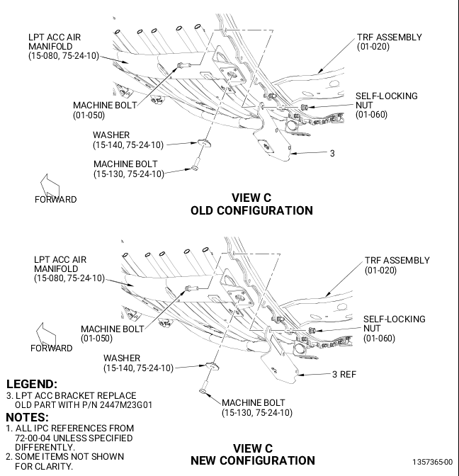
| (2) | Replace the support bracket (3, Figure 1) as follows: |
| (a) | Remove the machine bolt (15-130, 75-24-10) and washer (15-140) from the LPT ACC air manifold (15-080). |
| (b) | Remove the three self-locking nuts (01-060, 72-00-04) that attach the support bracket (3) to the aft face of the turbine rear frame (TRF) assembly (01-020) forward flange. Do not remove the three machine bolts (01-050). |
| (c) | Remove the support bracket (3) from the engine. |
| (d) | Apply lubricant (C02-058) to the threads of the three machine bolts (01-050). |
| (e) | Install the new LPT ACC bracket (3) on the three machine bolts (01-050) with the self-locking nuts (01-060). |
| (f) | Torque the three self-locking nuts (01-060) to 106-124 lb in. (12.0-14.0 Nm). |
| (g) | Torque the three self-locking nuts (01-060) again to 106-124 lb in. (12.0-14.0 Nm). |
| (h) | Install the machine bolt (15-130, 75-24-10) and washer (15-140) on the LPT ACC air manifold (15-080). |
| (i) | Torque the machine bolt (15-130) to 106-124 lb in. (12.0-14.0 Nm). |
| (3) | Replace the support brackets (4 and 5, Figure 1) as follows: |
| (a) | Remove the two self-locking nuts (FN1418-428), washers (NAS1149E0463R), and machine bolts (AS3418-10) from the aft flange of the TRF assembly (01-020, 72-00-04). |
| (b) | Remove the support brackets (4 and 5) from the engine. |
| (c) | Install the new support brackets (4 and 5) in the forward face of the TRF assembly aft flange with the machine bolts (AS3418-10), washers (NAS1149E0463R), and self-locking nuts (FN1418-428). |
| (4) | Hold the drain bracket (4, Figure 2) on the LPT ACC air manifold (15-080, 75-24-10) with two machine bolts (15-150). Hand tighten the machine bolts (15-150). |
| (5) | Install the sump tube (2, Figure 2) as follows: |
| (a) | Put the sump tube (2) on the engine and connect it loosely to the swivel nut (10-030, 79-22-40) at the main drain tube (01-680, 72-54-00). |
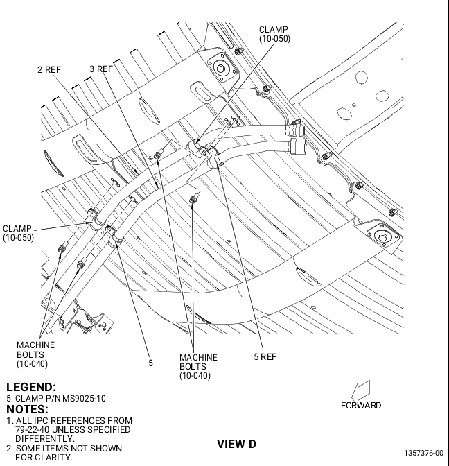
| (b) | Attach the sump tube (2) to the support bracket (2, Figure 1) with one cushioned loop clamp (clamp) (10-050, 79-22-40, Figure 2) and one machine bolt (10-040). Hand-tighten the machine bolts (10-040). |
| (c) | Attach the sump tube (2) with two clamps (10-050) and two machine bolts (10-040) to the LPT ACC air manifold (15-080, 75-24-10) brackets at two locations. Hand tighten the machine bolts (10-040, 79-22-40). |
| (6) | Install the B-sump tube (3, Figure 2) as follows: |
| (a) | Put the B-sump tube (3) on the engine and connect it loosely to the auxiliary drain tube (01-370, 72-54-00). |
| (b) | Attach the B-sump tube (3) to the support bracket (2, Figure 1) with one cushioned loop clamp (clamp) (10-060, 79-22-40, Figure 2) and one machine bolt (10-040). Hand tighten the machine bolt (10-040). |
| (c) | Attach the B-sump tube (3) with one clamp (10-060) and machine bolt (10-040) to the forward bolt hole of the drain bracket (4). Hand tighten the machine bolts (10-040). |
| (d) | Attach the B-sump tube (3) with two cushioned loop clamps (clamps) (5) and two machine bolts (10-040) to the LPT ACC air manifold (15-080, 75-24-10) brackets at two locations. Hand tighten the machine bolts (10-040, 79-22-40). |
| (7) | Torque the swivel nut (10-030, 79-22-40, Figure 2) and the B-nut of the B-sump tube (3) as follows: |
| (a) | Torque the swivel nut (10-030) connected to the sump tube (2) to 460-540 lb in. (52.0-61.0 Nm). |
| (b) | Torque the B-nut of the B-sump tube (3) to 460-540 lb in. (52.0-61.0 Nm). |
| (8) | Torque the machine bolts (10-040, 79-22-40, Figure 2) that attach the sump tube (2) and B-sump tube (3) to the support bracket (2, Figure 1) to 60-70 lb in. (6.8-7.9 Nm). |
| (9) | Install the drain support bracket (1, Figure 1) as follows: |
| (a) | Remove the two machine bolts (15-150, 75-24-10, Figure 2) used to hold the drain bracket (4) on the LPT ACC air manifold (15-080). |
| (b) | Put the drain support bracket (1, Figure 1) on the drain bracket (4, Figure 2) and LPT ACC air manifold (15-080, 75-24-10). |
| (c) | Align the top bolt holes in the drain support bracket (1, Figure 1), drain bracket (4, Figure 2), and LPT ACC air manifold (15-080, 75-24-10). |
| (d) | Install two machine bolts (15-150) through the bracket drain support bracket (1, Figure 1) and drain bracket (4, Figure 2). Hand tighten the machine bolts (15-150, 75-24-10) in the mounting platform nut plates on the LPT ACC air manifold (15-080). |
| (e) | Align the bottom bolt holes in the drain support bracket (1, Figure 1) with the mounting platform nut plates on the LPT ACC air manifold (15-080, 75-24-10, Figure 2). |
| (f) | Attach the drain support bracket (1, Figure 1) with two machine bolts (15-150, 75-24-10, Figure 2). Hand tighten the machine bolts (15-150). |
| (g) | Torque the four machine bolts (15-150) that attach the drain support bracket (1, Figure 1) and drain bracket (4, Figure 2) to the LPT ACC air manifold (15-080, 75-24-10) to 106-124 lb in. (12.0-14.0 Nm). |
| (h) | Attach the sump tube (2) to the drain support bracket (1, Figure 1) with one clamp (10-050, 79-22-40, Figure 2) and one machine bolt (10-040). Hand tighten the machine bolts (10-040). |
| (i) | Attach the B-sump tube (3) with one clamp (10-060) and one machine bolt (10-040) to the drain bracket (4) and drain support bracket (1, Figure 1). Hand tighten the machine bolts (10-040, 79-22-40, Figure 2). |
| (j) | Torque the machine bolts (10-040) to 60-70 lb in. (6.8-7.9 Nm). |
| (10) | Install the support bracket (6, Figure 2) as follows: |
| (a) | Remove the two self-locking nuts (01-060, 72-00-04) from the forward flange of the TRF assembly (01-020). Do not remove the two machine bolts (01-050). |
| (b) | Apply lubricant (C02-058) to the threads of the two machine bolts (01-050). |
| (c) | Put the support bracket (6) on the aft face of the forward flange of the TRF assembly (01-020) on the two machine bolts (01-050). |
| (d) | Attach the support bracket (6) with the self-locking nuts (01-060). |
| (e) | Torque the self-locking nuts (01-060) to 106-124 lb in. (12.0-14.0 Nm). |
| (f) | Torque the self-locking nuts (01-060) again to 106-124 lb in. (12.0-14.0 Nm). |
| (11) | Install the drain manifold (1, Figure 2) as follows: |
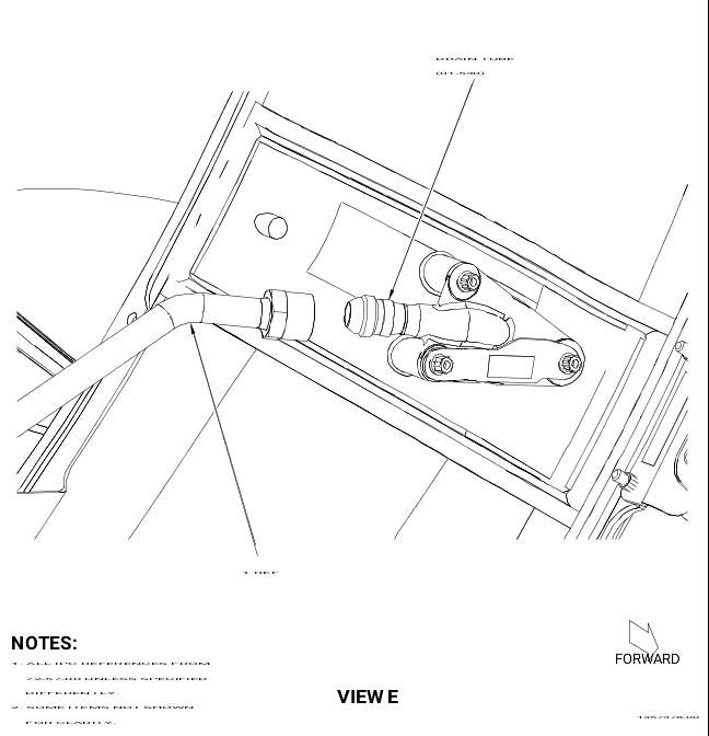
| (a) | Put the drain manifold (1) on the TRF assembly (01-020, 72-00-04) and connect the B-nut fittings to the B-sump tube (3), sump tube (2), and drain tube (01-530, 72-57-00). Hand tighten the B-nut fittings. |
| (b) | Install one machine bolt (7) to attach the drain manifold (1) to the support bracket (6). Hand tighten the machine bolt (7). |
| (c) | Attach the drain manifold (1) to the C-sump tube bracket (45-400, 72-00-02) with one cushioned loop clamp (clamp) (10-100, 79-22-40) and one machine bolt (10-090). Hand tighten the machine bolt (10-090). |
| (d) | Attach the drain manifold (1) to the support bracket (4, Figure 1) with one clamp (10-100, 79-22-40, Figure 2) and one machine bolt (10-090). Hand tighten the machine bolt (10-090). |
| (e) | Attach the drain manifold (1) to the support bracket (5, Figure 1) with two clamps (8 and 10-100, 79-22-40, Figure 2) and two machine bolts (10-090). Hand tighten the machine bolts (10-090). |
| (f) | Torque the B-nut fitting that connects the drain manifold (1) to the drain tube (01-530, 72-57-00) to 662-778 lb in. (74.8-87.9 Nm). |
| (g) | Torque the B-nut fitting that connects the drain manifold (1) to the sump tube (2) to 662-778 lb in. (74.8-87.9 Nm). |
| (h) | Torque the B-nut fitting that connects the B-sump tube (3) to the drain manifold (1) to 662 to 778 lb in. (74.7 to 87.9 Nm). |
| (i) | Install the tube cap (10-120, 79-22-40) on the drain manifold (1). |
| (j) | Torque the tube cap (10-120) to 262-308 lb in. (29.6-34.8 Nm). |
| (k) | Torque the machine bolts (10-090) that attach the drain manifold (1) to the C-sump tube bracket (45-400, 72-00-02) and support brackets (4 and 5, Figure 1) to 60-70 lb in. (6.8-7.9 Nm). |
| (l) | Torque the machine bolt (7, Figure 2) that attaches the drain manifold (1) to the support bracket (6) to 106-124 lb in. (12.0-14.0 Nm). |
| (12) | Torque the four machine bolts (10-040, 79-22-40, Figure 2) that attach the sump tube (2) and B-sump tube (3) to the LPT ACC air manifold (15-080, 75-24-10) to 60-70 lb in. (6.8-7.9 Nm). |
| (13) | Attach the W30 harness (01-010, 73-21-66) and W31 harness (05-010) to the drain support bracket (1, Figure 1) as follows: |
| (a) | Put the W31 harness (05-010) on the drain support bracket (1) with the harness bracket bolt holes aligned with the nut plates in the drain support bracket (1). |
| (b) | Install two machine bolts (05-030) through the harness brackets in the nut plates of the drain support bracket (1). |
| (c) | Torque the machine bolts (05-030) to 106-124 lb in. (12.0-14.0 Nm). |
| (d) | Put the W30 harness (01-010) on the drain support bracket (1) with the harness bracket bolt holes aligned with the nut plates in the drain support bracket (1). |
| (e) | Install two machine bolts (01-040) through the harness brackets in the nut plates of the drain support bracket (1). |
| (f) | Torque the machine bolts (01-040) to 106-124 lb in. (12.0-14.0 Nm). |
| (14) | Install the sensing element (05-111, 71-00-02, Figure 1) on the drain support bracket (1) as follows: |
| (a) | Attach the clamps (05-120) to the drain support bracket (1) at three locations with six double hex bolts (15-010, 75-24-10). |
| (b) | Attach the end lug bracket (15-040) to the LPT ACC air manifold with two double hex bolts (15-010). |
| (c) | Torque the double hex bolts (15-010) that attach the clamps (05-120, 71-00-02) to 51-59 lb in. (5.8-6.7 Nm). |
| (d) | Torque the double hex bolts (15-010) that attach the end lug bracket (15-040, 75-24-10) to 60-70 lb in. (6.8-7.9 Nm). |