| GEnx-1B SERVICE BULLETIN - 72-0057 R01 | Revised: 07/27/2016 | |
| SB 72-0057 R01 POWERPLANT - Lower Bifi Bracket Kit (71-00-00) - Introduction of New Hardware for Hydraulic Supply Line | Issued: 12/09/2011 | |
| GEnx-1B SERVICE BULLETIN - 72-0057 R01 | Revised: 07/27/2016 | |
| SB 72-0057 R01 POWERPLANT - Lower Bifi Bracket Kit (71-00-00) - Introduction of New Hardware for Hydraulic Supply Line | Issued: 12/09/2011 | |
| GE PROPRIETARY INFORMATION | |
| The information contained in this document is GE proprietary information and is disclosed in confidence. It is the property of GE and shall not be used, disclosed to others or reproduced without the express written consent of GE, including, but without limitation, it is not to be used in the creation, manufacture, development, or derivation of any repairs, modifications, spare parts, designs, or configuration changes or to obtain FAA or any other government or regulatory approval to do so. If consent is given for reproduction in whole or in part, this notice and the notice set forth on each page of this document shall appear in any such reproduction in whole or in part. | |
| This technical data is considered EAR controlled pursuant to 15 CFR Parts 730-774 respectively. Transfer of this data by any means to a Non-US Person, whether in the United States or abroad, without the proper U.S. Government authorization (e.g., License, exemption, NLR, etc.), is strictly prohibited. | |
| Copyright (2016) General Electric Company, U.S.A. |
| TRANSMITTAL INFORMATION |
| REVISION 1 TO SERVICE BULLETIN 72-0057 |
| Revision 1 is issued to update paragraphs 1., PLANNING INFORMATION, 2., MATERIAL INFORMATION, and 3., ACCOMPLISHMENT INSTRUCTIONS. |
| The original was issued December 09, 2011. Revision bars in the left margin identify changes. |
| 1. | PLANNING INFORMATION |
| A. | Effectivity |
|
| This Service Bulletin is applicable to these GEnx-1B engines: |
| • |
|
| These serial numbers are the best available data. |
| The hinged block clamp P/N ER3752P01 and the machine bolt P/N AS3237-08 are affected by this Service Bulletin. |
| B. | Description |
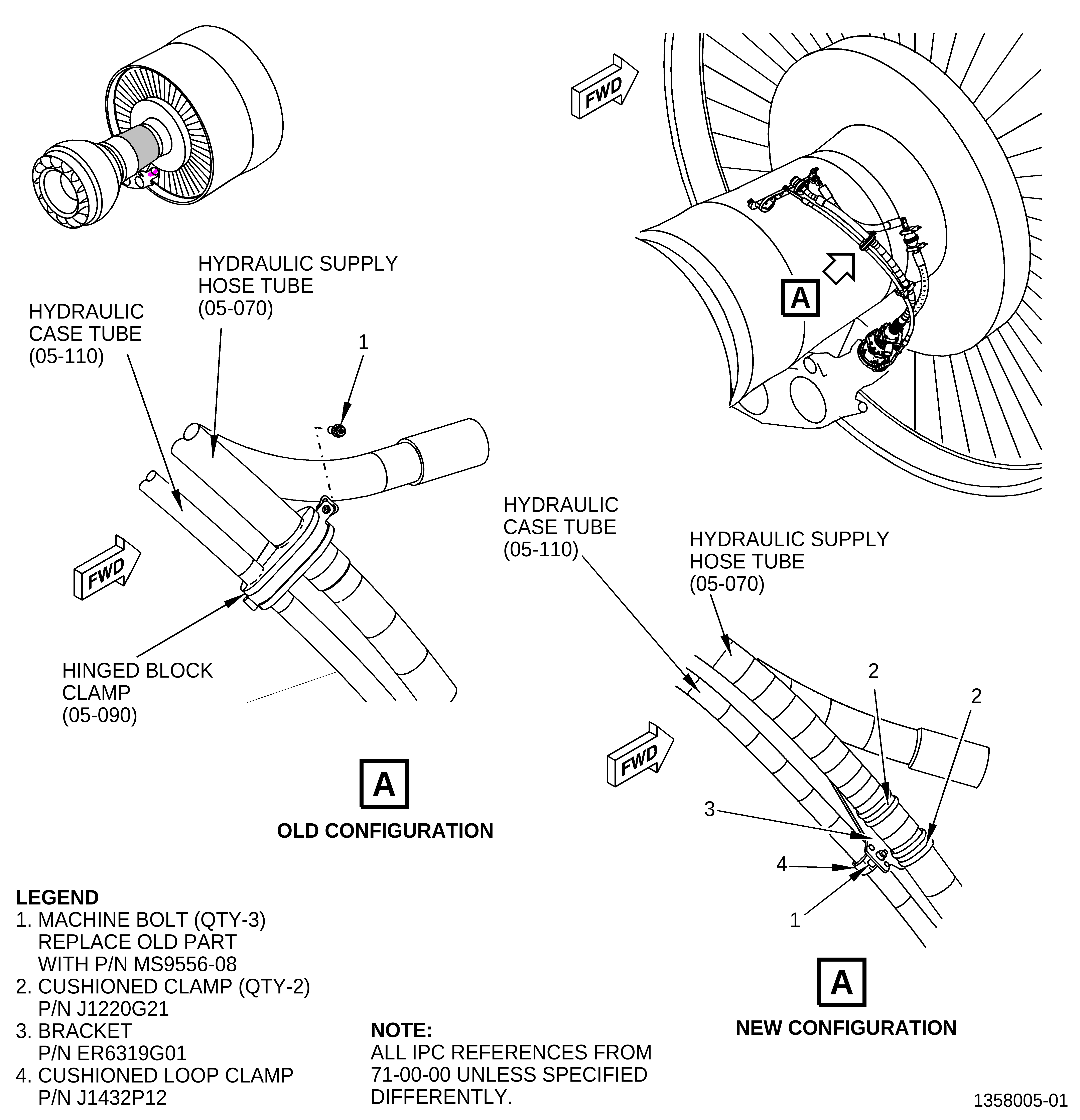
| This Service Bulletin introduces a new bracket P/N ER6319G01, machine bolts P/N MS9556-08, cushioned clamps P/N J1220G21, and cushioned loop clamp P/N J1432P12. |
| C. | Compliance |
| Category 7 |
| GE recommends that you do this Service Bulletin at customer's convenience/option. |
| NOTE: |
|
| D. | Concurrent Requirements |
| None. |
| E. | Reason |
| (1) | Objective: |
| To introduce new parts and improve maintainability. |
| (2) | Condition: |
| The hinged block clamp P/N ER3752P01 that attaches the hydraulic supply hose tube and the hydraulic case drain hose tube (hydraulic case tube) tends to move from its original position. The hinged block clamp P/N ER3752P01 tends to move up toward the interface at the strut hanger. This movement could cause that the hydraulic supply hose tube and the hydraulic case tube make contact. |
| (3) | Cause: |
| The current hinged block clamp P/N ER3752P01 does not have a good retention feature, which allows the movement upwards. |
| (4) | Improvement: |
| The new design incorporates two cushioned clamps on the hydraulic supply hose tube and a cushioned loop clamp on the hydraulic case tube, all of them attached to a bracket. This bracket has anti-rotation features for two of the three clamps to insure proper orientation of the hose assemblies. |
| (5) | Substantiation: |
| Substantiation is by comparative analysis. |
| F. | Approval |
| This Service Bulletin has been reviewed by the FAA and the repair(s) and modification(s) herein comply with the applicable Federal Aviation Regulations and are FAA APPROVED for installation in the model(s) listed in this Service Bulletin. |
| G. | Manpower |
| No additional man-hours are required to comply with this Service Bulletin. |
| H. | Weight and Balance |
| Weight and balance are not changed. |
| I. | References (Use the latest version of these documents) |
| GEK 112851, GEnx-1B Engine Manual (EM) |
| GEK 112864, GEnx-1B Engine Illustrated Parts Catalog (EIPC) |
| NOTE: |
|
| J. | Publications Affected |
| GEK 112851, GEnx-1B Engine Manual (EM) |
| GEK 112864, GEnx-1B Engine Illustrated Parts Catalog (EIPC) |
| K. | Interchangeability |
| The new hardware must be introduced as a set. |
| L. | Software Accomplishment Summary |
| Not applicable. |
| 2. | MATERIAL INFORMATION |
| A. | Material - Price and Availability |
| (1) | Parts necessary to do this Service Bulletin: |
|
| *Parts not supplied by GE Engine Services Distribution L.L.C. Procure through local purchase. |
| ** Parts not supplied by GE Engine Services Distribution L.L.C. Procure from: CAGE 81205. |
| V81205 The Boeing Company Boeing Defense, Space, and Security 7755 East Marginal Way South Seattle, WA 98124-4002 U.S.A |
| NP = Not Provisioned |
| NOTE: |
|
| (2) | Other Spare Parts: |
| None. |
| (3) | Consumables: |
| None. |
| B. | Industry Support Information |
| None. |
| C. | Configuration Chart |
|
| Operation Codes AD=Add DE=Delete RE=Replace RM=Remains |
| Change Code 5=Qualified interchangeability. Refer to paragraph 1.K., Interchangeability. |
| Support Codes A=Old parts will no longer be supplied. E=Old parts will be supplied, and can be used at other engine locations. |
| D. | Parts Disposition |
| None. |
| E. | Tooling - Price and Availability |
| None. |
| 3. | ACCOMPLISHMENT INSTRUCTIONS |
| A. | Removal |
| (1) | Removal instructions for the machine bolt (1, Figure 1) and hinged block clamp (05-090) have not changed. Refer to the GEnx-1B EM, 72-00-00, DISASSEMBLY 001. |
| B. | Installation |
| (1) | Install the bracket (3, Figure 1), machine bolts (1), cushioned clamps (2), and cushioned loop clamp (4). Refer to the GEnx-1B EM, 72-00-00, ASSEMBLY 001, Subtask 72-00-00-400-013. |