| GEnx-1B SERVICE BULLETIN - 72-0065 R00 | Revised: 01/18/2012 | |
| SB 72-0065 R00 ENGINE - Propulsor Module Assembly (72-00-00) - Introduction of One-Port TBV Duct | Issued: 01/18/2012 | |
| GEnx-1B SERVICE BULLETIN - 72-0065 R00 | Revised: 01/18/2012 | |
| SB 72-0065 R00 ENGINE - Propulsor Module Assembly (72-00-00) - Introduction of One-Port TBV Duct | Issued: 01/18/2012 | |
| 1. | PLANNING INFORMATION |
| A. | Effectivity |
|
| This Service Bulletin has been introduced in production to these GEnx-1B engines: |
| • |
|
| These serial numbers are the best available data. |
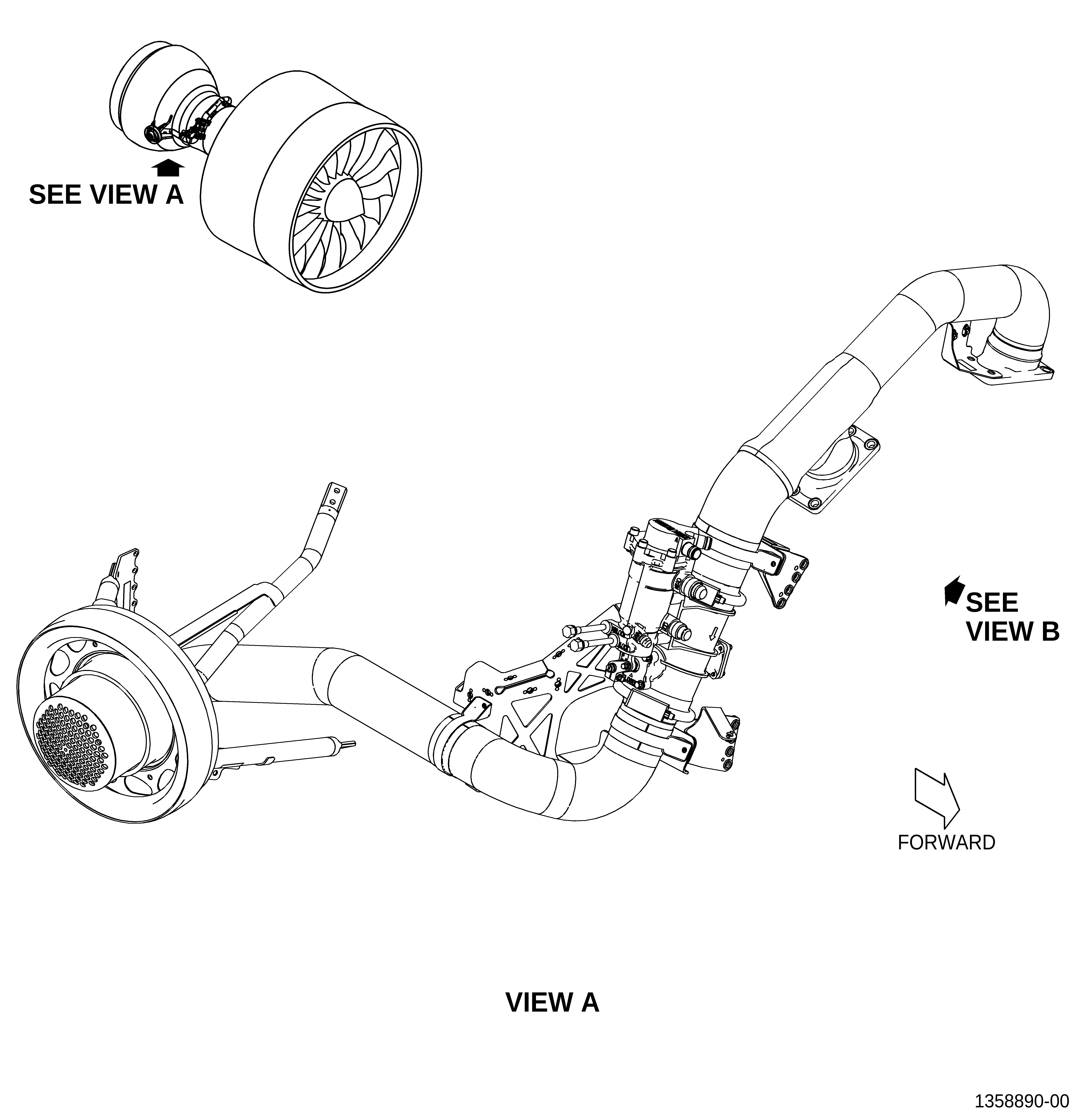
| The transient bleed air manifold [transient bleed valve (TBV) duct] P/N 2446M11G01, support brackets (brackets) P/N 2412M02G01 and P/N 2372M32G01, and retaining strap P/N 9134M25P57 are affected by this Service Bulletin. |
| B. | Description |
| This Service Bulletin releases to production a new TBV duct P/N 2459M31G01 and all surrounding hardware. This new TBV duct goes from stage 10 port to the TBV. |
| C. | Compliance |
| Category 7 |
| GE recommends that you do this Service Bulletin at customer's convenience. |
| NOTE: |
|
| D. | Concurrent Requirements |
| None. |
| E. | Reason |
| (1) | Objective: |
| To introduce new parts, improve maintainability, and reduce weight. |
| (2) | Condition: |
| The two-port TBV duct is heavier than the new designed one-port TBV duct. |
| (3) | Cause: |
| Unnecessary weight and space created by the two-port TBV duct. |
| (4) | Improvement: |
| The new one-port TBV duct results lighter than the two-port TBV duct. Additionally, it is easier to manufacture and can be removed and installed from the engine on wing. |
| (5) | Substantiation: |
| Substantiation is by comparative analysis and test. |
| F. | Approval |
| This Service Bulletin has been reviewed by the FAA and the repair(s) and modification(s) herein comply with the applicable Federal Aviation Regulations and are FAA APPROVED for installation in the model(s) listed in this Service Bulletin. |
| G. | Manpower |
| After you get access to the TBV, you will need approximately 5 man-hours to do the replacement portion of this Service Bulletin. |
| H. | Weight and Balance |
| The complete compliance with this Service Bulletin decreases weight by 5.06 lb (2.30 kg). |
| I. | References (Use the latest version of these documents) |
| Boeing 787 Aircraft Maintenance Manual (AMM) |
| GEK 9250, Commercial Engine Standard Practices Manual |
| GEK 112851, GEnx-1B Engine Manual (EM) |
| GEK 112864, GEnx-1B Engine Illustrated Parts Catalog (EIPC) |
| NOTE: |
|
| J. | Publications Affected |
| GEK 112851, GEnx-1B Engine Manual (EM) |
| GEK 112864, GEnx-1B Engine Illustrated Parts Catalog (EIPC) |
| Boieng 787 Aircraft Maintenance Manual (AMM) |
| K. | Interchangeability |
| Qualified interchangeability. |
| All parts must be introduced concurrently. Mixing of the new and old hardware is not permitted. |
| L. | Software Accomplishment Summary |
| Not applicable. |
| 2. | MATERIAL INFORMATION |
| A. | Material - Price and Availability |
| (1) | Parts necessary to do this Service Bulletin: |
|
| NOTE: |
|
| (2) | Other Spare Parts: |
| None. |
| (3) | Consumables: |
|
| B. | Industry Support Information |
| None. |
| C. | Configuration Chart |
|
| Operation Codes AD=Add RE=Replace RM=Remains |
| Change Codes. 5=Qualified interchangeability. Refer to paragraph 1.K., Interchangeability. |
| Support Codes B=Old parts will be supplied until all old parts are sold. |
| D. | Parts Disposition |
| Discard old parts. |
| E. | Tooling - Price and Availability |
| None. |
| 3. | ACCOMPLISHMENT INSTRUCTIONS |
| A. | General |
| (1) | Make sure that personnel read the assembly and disassembly techniques section. Refer to the SPM, 70-10-00, ASSEMBLY AND DISASSEMBLY TECHNIQUES, TASK 70-10-00-800-009. |
| (2) | Install protective covers/plugs on tubes and hoses to prevent damage and contamination. |
| (3) | Make sure that personnel obey all site safety and environmental controls or personal injury can occur. |
| B. | Removal of the TBV System |
| (1) | Remove the TBV system. Refer to the GEnx-1B EM, 72-00-02, DISASSEMBLY 003, Subtask 72-00-02-030-393. |
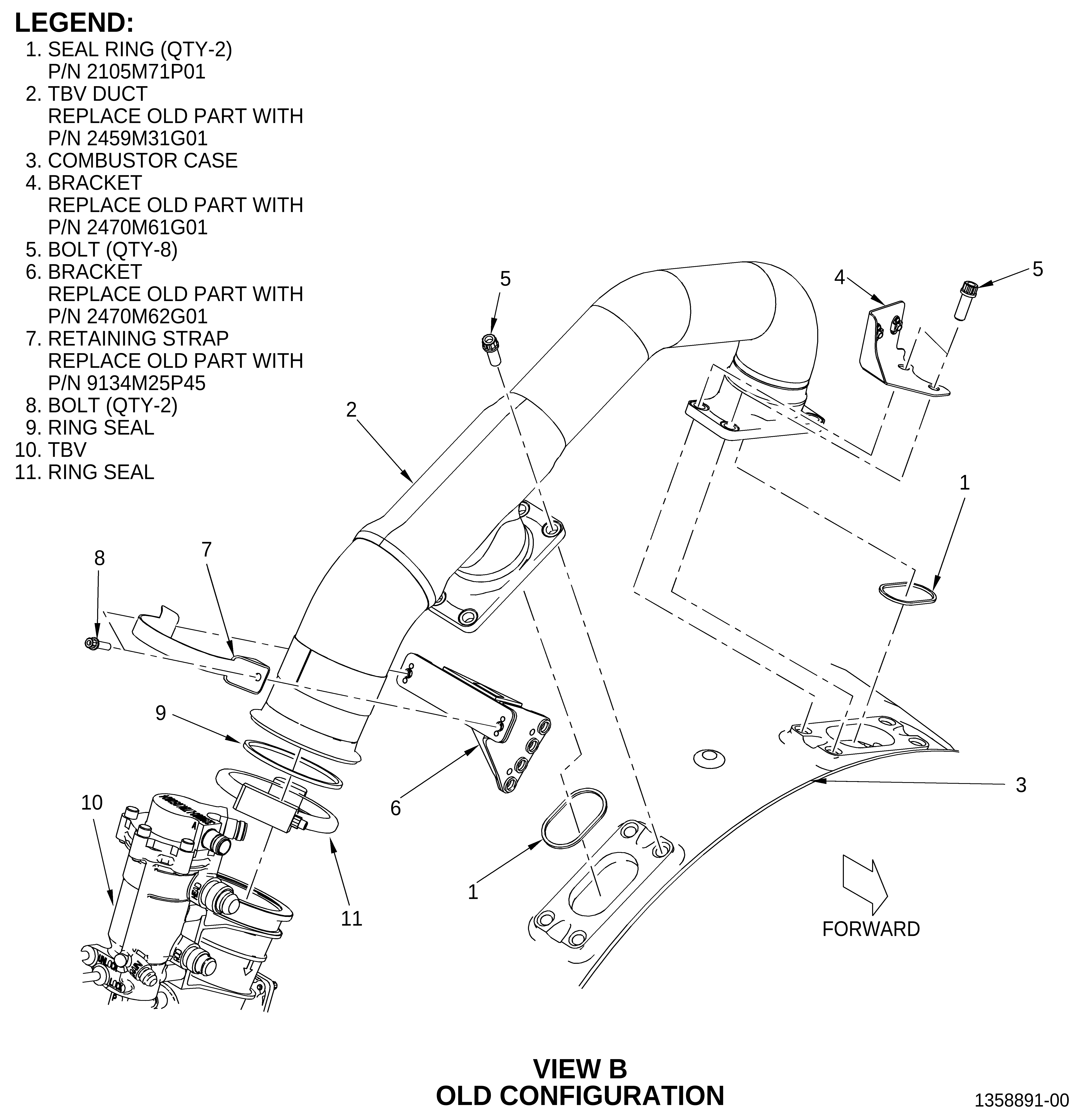
| (2) | Discard the old TBV duct (2, Figure 1), brackets (4 and 6), retaining strap (7), and seal rings (1). |
| C. | Installation of the TBV System |
| (1) | Installation procedures for the TBV system have not changed, except for the installation of the new TBV duct (2, Figure 1). Refer to the GEnx-1B EM, 72-00-02, ASSEMBLY 004, Subtask 72-00-02-440-122 and to step 3.C.(2) of this Service Bulletin for the new TVB duct (2) installation. |
| (2) | Install the new TBV duct (2, Figure 1) as follows: |
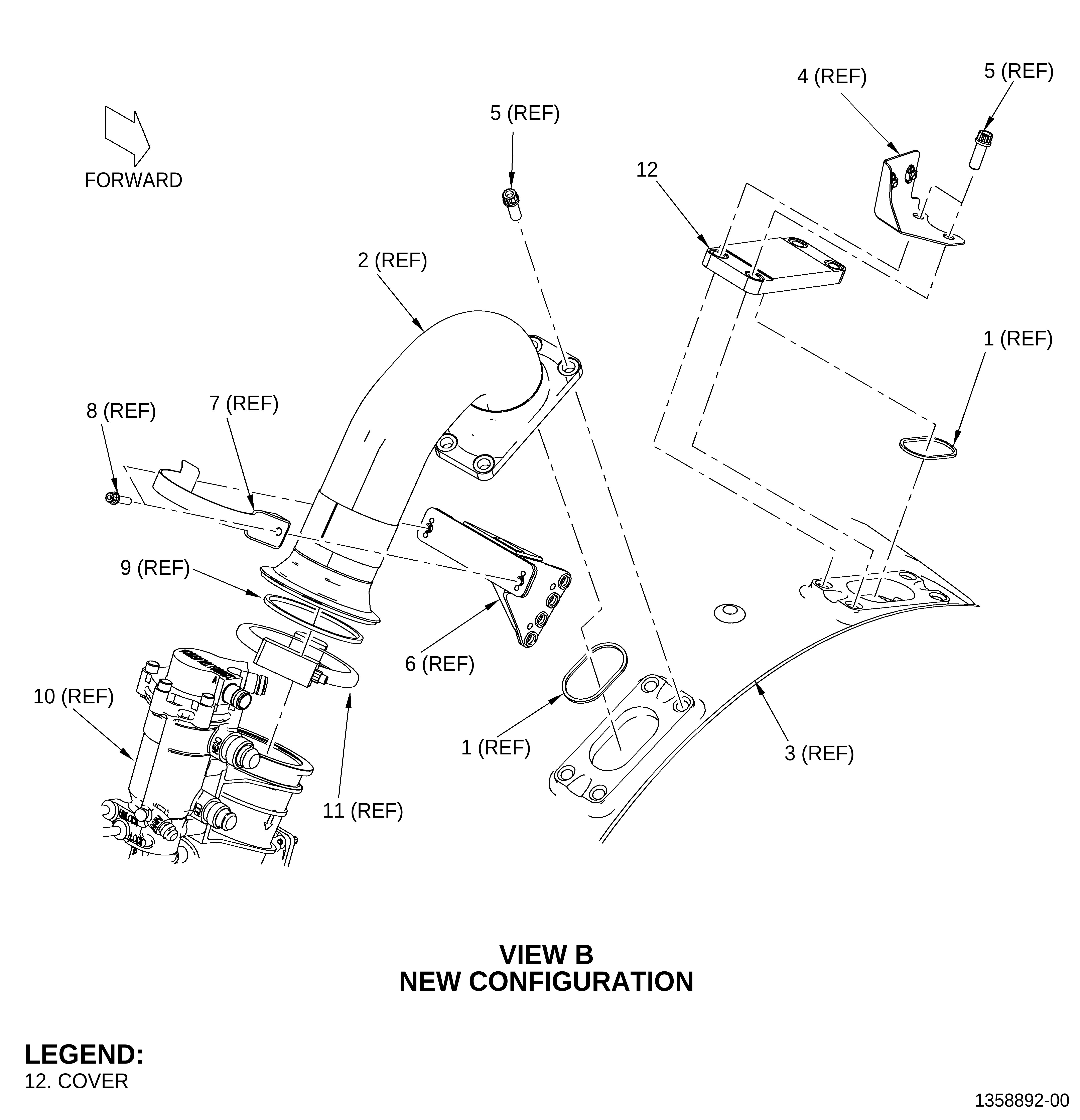
| (a) | Install two new seal rings (1), one on the TBV duct (2) and one on the cover (12). |
| NOTE: |
|
| (b) | Install the cover (12) and the TBV duct (2) on the combustor case (3) as follows: |
| 1 | Install the cover (12) in position at the 12:00 o'clock port on the combustor case (3). |
| 2 | Install the bracket (4) on the cover (12). Align the holes of the bracket (4) with the holes on the right side of the cover (12). |
| 3 | Attach the cover (12) and the bracket (4) to the combustor case (3) with bolts (5). |
| 4 | Install the TBV duct (2) in position at the 1:00 o'clock port on the combustor case (3). |
| 5 | Install the TBV duct (2) to the combustor case (3) with bolts (5). |
| 6 | Install the TBV duct (2) to the bracket (6) with a retaining strap (7) and bolts (8). |
| 7 | Install a ring seal (9) between the TBV duct (2) and the TBV (10). |
| NOTE: |
|
| 8 | Install the TBV (10) in position on the TBV duct (2) with the lock/unlock rods pointed outboard and perpendicular to the combustor case (3). |
| 9 | Attach the TBV (10) to the TBV duct (2) with a ring seal (11). Install the ring seal (11) with the nut outboard and pointed forward. |
| NOTE: |
|
| 10 | Torque the bolts (5) at the 12:00 o'clock port in a criss-cross pattern to 368-432 lb in. (41.6-48.8 Nm). |
| 11 | Torque the bolts (5) at the 1:00 o'clock port in a criss-cross pattern to 368-432 lb in. (41.6-48.8 Nm). |
| 12 | Torque the nut of the ring seal (11) to 106-124 lb in. (12.0-14.0 Nm). |
| 13 | Torque the bolts (8) on the retaining strap (7) to 106-124 lb in. (12.0-14.0 Nm). |