| GEnx-1B SERVICE BULLETIN - 72-0071 R00 | Revised: 01/26/2012 | |
| SB 72-0071 R00 ENGINE - Fan Stator Module, Lower Bifurcation, and Related Parts (72-00-00) - Introduction of New Support Strap and Machine Bolts | Issued: 01/26/2012 | |
| GEnx-1B SERVICE BULLETIN - 72-0071 R00 | Revised: 01/26/2012 | |
| SB 72-0071 R00 ENGINE - Fan Stator Module, Lower Bifurcation, and Related Parts (72-00-00) - Introduction of New Support Strap and Machine Bolts | Issued: 01/26/2012 | |
| 1. | PLANNING INFORMATION |
| A. | Effectivity |
|
| This Service Bulletin is applicable to these GEnx-1B engines: |
| • |
|
| These serial numbers are the best available data. |
| The machine bolts P/N MS9556-12 and P/N MS9556-16 that attach the blanket P/N 2402M87P01 are affected by this Service Bulletin. |
| B. | Description |
| This Service Bulletin provides instructions to install the new support strap P/N 2475M75P01 over the blanket and releases new machine bolts P/N MS9556-16 and P/N MS9556-20 to attach the support strap. |
| C. | Compliance |
| Category 9 |
| Information only. |
| NOTE: |
|
| D. | Concurrent Requirements |
| None. |
| E. | Reason |
| (1) | Objective: |
| To introduce new parts and to improve maintainability. |
| (2) | Condition: |
| The blanket is installed at the bottom of the lower bifurcation drain manifold and made of a soft pliable material. This condition allows the blanket to interfere in thrust reversers' closing path. |
| (3) | Cause: |
| Due to the nature of the blanket's soft pliable material condition, the blanket is pinched by the door halves, preventing the doors to close and causing damage to the blanket. |
| (4) | Improvement: |
| The new support strap provides support to the existing blanket and holds the blanket away from the thrust reversers door's closing path. |
| (5) | Substantiation: |
| Substantiation is by comparative analysis. |
| F. | Approval |
| This Service Bulletin has been reviewed by the FAA and the repair(s) and modification(s) herein comply with the applicable Federal Aviation Regulations and are FAA APPROVED for installation in the model(s) listed in this Service Bulletin. |
| G. | Manpower |
| After you get access to the blanket, you will need approximately 1.0 man-hour for each engine or component. |
| H. | Weight and Balance |
| The complete compliance with this Service Bulletin increases weight by 0.50 lb (0.23 kg). |
| I. | References (Use the latest version of these documents) |
| GEK 112851, GEnx-1B Engine Manual (EM) |
| GEK 112864, GEnx-1B Engine Illustrated Parts Catalog (EIPC) |
| NOTE: |
|
| J. | Publications Affected |
| GEK 112851, GEnx-1B Engine Manual (EM) |
| GEK 112864, GEnx-1B Engine Illustrated Parts Catalog (EIPC) |
| K. | Interchangeability |
| Qualified interchangeability. |
| The support strap and the machine bolts must be introduced as a complete set only. |
| L. | Software Accomplishment Summary |
| Not applicable. |
| 2. | MATERIAL INFORMATION |
| A. | Material - Price and Availability |
| (1) | Parts necessary to do this Service Bulletin: |
|
|||||||||||||||||||||||||||||||||||||||||||||||||||||||||||||||||||||||||||||||||||||||||||||||||
| NOTE: |
|
| (2) | Other Spare Parts: |
| None. |
| (3) | Consumables: |
| None. |
| B. | Industry Support Information |
| None. |
| C. | Configuration Chart |
|
| Operation Codes AD=Add RM=Remains QTC=Quantity Change |
| Change Codes 5=Qualified interchangeability. Refer to paragraph 1.K., Interchangeability. |
| Support Codes E=Old parts will be supplied, and can be used at other engine locations. |
| D. | Parts Disposition |
| Use serviceable old parts at other engine locations. |
| E. | Tooling - Price and Availability |
| None. |
| 3. | ACCOMPLISHMENT INSTRUCTIONS |
| A. | General |
| (1) | Remove the two machine bolts (1, Figure 1) that attach the blanket (25-620, 72-00-00) to the lower bifurcation firewall (01-180, 72-00-03). Discard the machine bolts (1). |
| (2) | Remove the two machine bolts (2) that attach the thermal blanket (25-630, 72-00-00) to support brackets (25-270 and 25-300). Discard the machine bolts (2). |
| (3) | Remove the electrical harnesses inside the blanket (25-620) from the spring clips of the support brackets (25-270 and 25-300), the left side cable shield (01-040, 72-00-03), and the right side cable shift (01-050). |
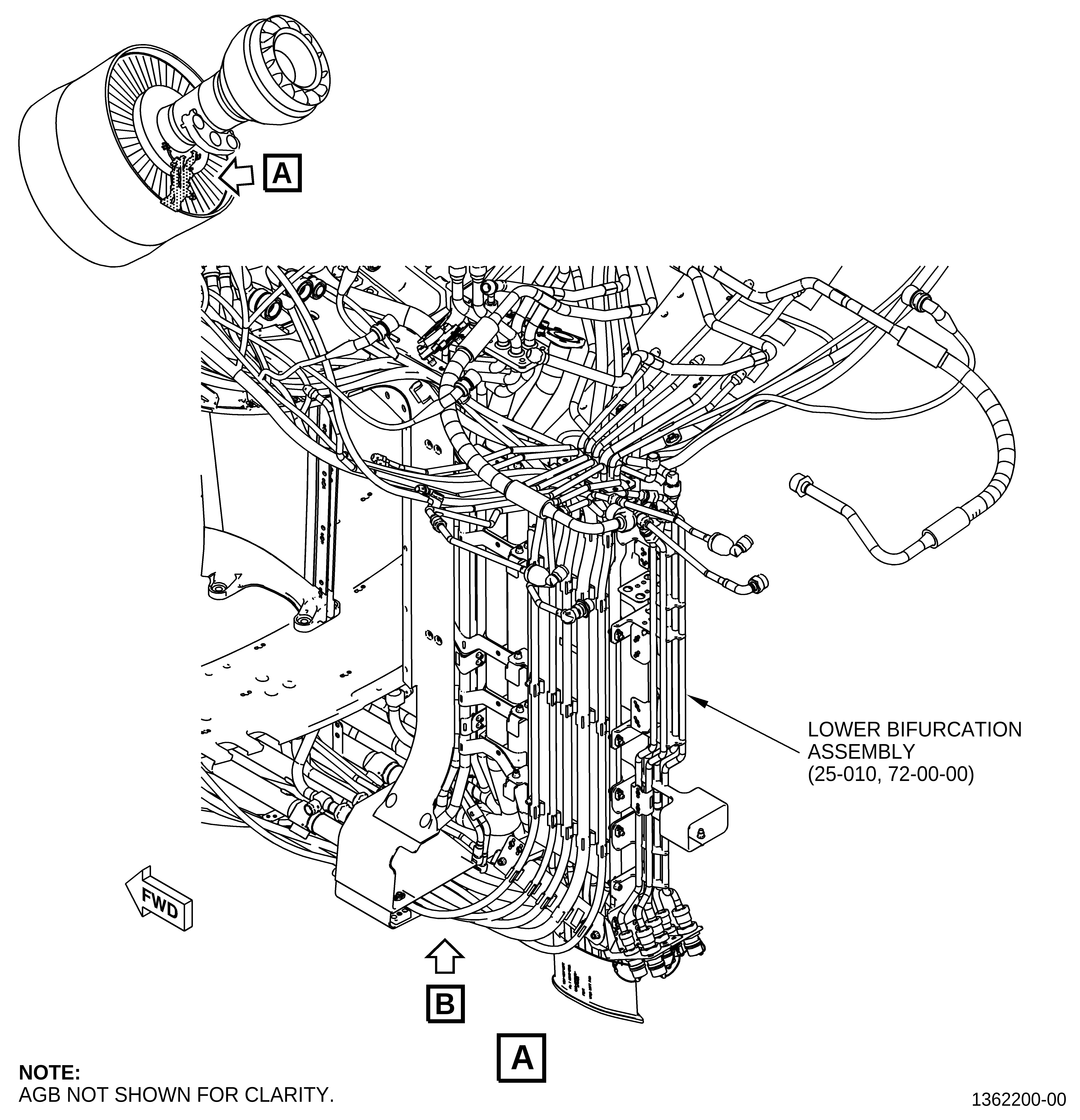
| (4) | Pull the electrical harness slack up into the engine core area above the lower bifurcation assembly (25-010, 72-00-00) creating better clearance at the 6:00 o'clock position in the blanket area. |
| (5) | Install the electrical harnesses back into the spring clips of the support brackets (25-270 and 25-300), the left side cable shield (01-040, 72-00-03), and the right side cable shift (01-050). |
| (6) | Put the support strap (3) around the blanket (25-620, 72-00-00). |
| (7) | Align the bolt holes of the support strap (3) with the bolt hole grommets of the lower bifurcation firewall (01-180, 72-00-03) and the holes of the support brackets (25-270 and 25-300, 72-00-00). |
| (8) | Install the two new machine bolts (1) through the support strap holes and the bolt hole grommets of the lower bifurcation firewall (01-180, 72-00-03) finger tight only. |
| (9) | Install the two new machine bolts (2) through the support strap holes into the support brackets (25-270 and 25-300, 72-00-00) finger tight only. |
| (10) | Torque the machine bolts (1 and 2) to 51-59 lb in. (5.8-6.7 N.m). |