| GEnx-1B SERVICE BULLETIN - 72-0078 R00 | Revised: 03/06/2012 | |
| SB 72-0078 R00 ENGINE - High Pressure Compressor Stator Assembly (72-30-00) - HPC Stator Forward Case Split Flange Bolt Orientation Change | Issued: 03/06/2012 | |
| GEnx-1B SERVICE BULLETIN - 72-0078 R00 | Revised: 03/06/2012 | |
| SB 72-0078 R00 ENGINE - High Pressure Compressor Stator Assembly (72-30-00) - HPC Stator Forward Case Split Flange Bolt Orientation Change | Issued: 03/06/2012 | |
| 1. | PLANNING INFORMATION |
| A. | Effectivity |
| * * * FOR GEnx-1B54, -1B58, -1B64, -1B67, -1B70 |
| This Service Bulletin is applicable to these GEnx-1B engines: |
| • |
|
| This Service Bulletin has been introduced in production to these GEnx-1B engines: |
| • |
|
| These serial numbers are the best available data. |
| The hexagon shear bolt P/N J817P036A installed in the No. 15 bolt hole of the high pressure compressor (HPC) stator assembly split-line flange (No. 15 bolt), located on the 3:00 o'clock position aft looking forward (ALF) and attaching self-locking nut P/N J628P07 are affected by this Service Bulletin. |
| B. | Description |
| This Service Bulletin provides a procedure to reverse the orientation of the No. 15 bolt. |
| C. | Compliance |
| Category 3 |
| GE recommends that you do this Service Bulletin at the next shop visit of the engine or module when the accessory gearbox assembly is removed from the engine. |
| NOTE: |
|
| This Service Bulletin is offered to improve the reliability or performance of your GE product, or to help prevent the occurrence of the event or condition described in this Service Bulletin. If the operator elects not to participate in the bulletin, that decision will be taken into consideration by GE in evaluating future product performance issues that may arise in the operators fleet. |
| D. | Concurrent Requirements |
| None. |
| E. | Reason |
| (1) | Objective: |
| To improve maintainability. |
| (2) | Condition: |
| The 3:00 o'clock position (ALF) of the lower variable stator vane (VSV) actuation ring has the potential to contact the bottom of the No. 15 bolt. |
| (3) | Cause: |
| Original stack analysis of the stage 4 VSV system hardware did not show that contact could occur between the actuation ring and No. 15 bolt. |
| (4) | Improvement: |
| The No. 15 bolt is now assembled head down to prevent any contact with the end of the stage 4 VSV actuation ring. |
| (5) | Substantiation: |
| Substantiation is by comparative analysis. |
| F. | Approval |
| This Service Bulletin has been reviewed by the FAA and the repair(s) and modification(s) herein comply with the applicable Federal Aviation Regulations and are FAA APPROVED for installation in the model(s) listed in this Service Bulletin. |
| G. | Manpower |
| After you get access to the HPC module, you will need approximately 2 man-hours for each engine. |
| H. | Weight and Balance |
| Weight and balance are not changed. |
| I. | References (Use the latest version of these documents) |
| GEK 112851, GEnx-1B Engine Manual (EM) |
| GEK 112862, GEnx-1B Cleaning, Inspection, and Repair Manual (CIR) |
| GEK 112864, GEnx-1B Engine Illustrated Parts Catalog (EIPC) |
| NOTE: |
|
| J. | Publications Affected |
| GEK 112851, GEnx-1B Engine Manual (EM) |
| K. | Interchangeability |
| Not applicable. |
| L. | Software Accomplishment Summary |
| Not applicable. |
| 2. | MATERIAL INFORMATION |
| A. | Material - Price and Availability |
| (1) | Parts necessary to do this Service Bulletin: |
| None. |
| (2) | Other Spare Parts: |
|
| NOTE: |
|
| (3) | Consumables: |
|
| B. | Industry Support Information |
| None. |
| C. | Configuration Chart |
| Not applicable. |
| D. | Parts Disposition |
| None. |
| E. | Tooling - Price and Availability |
| None. |
| 3. | ACCOMPLISHMENT INSTRUCTIONS |
| A. | General |
| (1) | Before you do this Service Bulletin do the task that follows to allow access to the affected parts: |
| (a) | Remove the main body heat shield P/N 2343M77G02. Refer to the GEnx-1B EM, 72-00-02, DISASSEMBLY 003. |
| B. | Reorientation Procedure |
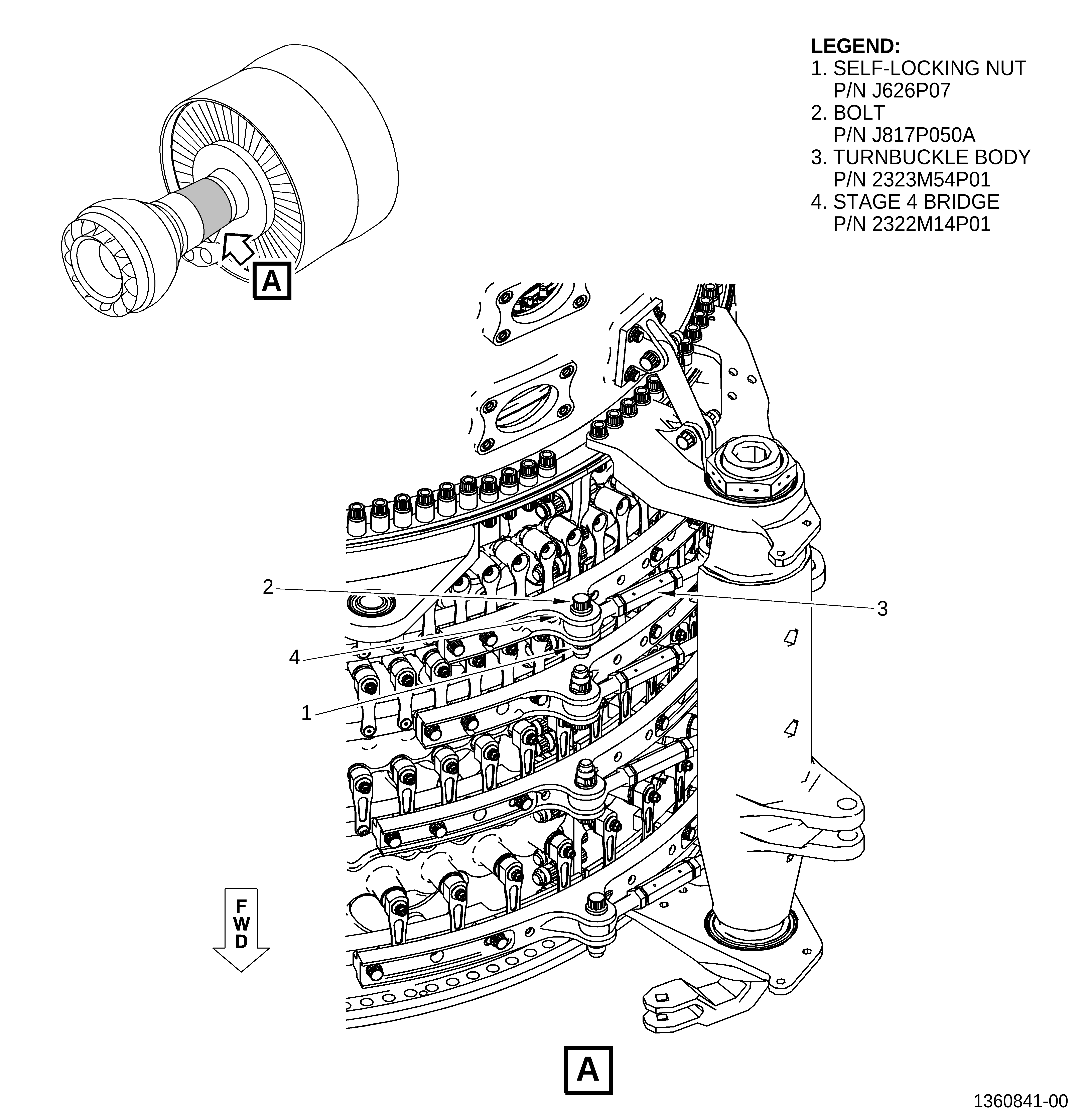
| (1) | Disconnect the turnbuckle body (3, Figure 1) from the 3:00 o'clock position (ALF) of the HPC stator assembly as follows: |
| (a) | Remove the self-locking nut (1) from the bolt (2) on the stage 4 bridge (4) and the turnbuckle body (3). |
| (b) | Remove the bolt (2) from the stage 4 bridge (4) and the turnbuckle body (3). |
| (c) | Remove the turnbuckle body (3) from the stage 4 bridge (4) clevis and make sure it is clear of the splitline flange location. Secure the turnbuckle body from the work area as required. |
| (2) | Remove the stage 4 bridge from the stage 4 actuating rings on the 3:00 o'clock position (ALF) of the HPC stator assembly as follows: |
| (a) | Remove the safety cable (C10-143) from the bolts. |
| (b) | Remove the bolts from the stage 4 bridge. |
| (c) | Remove the pins from the stage 4 bridge. |
| (d) | Remove the stage 4 bridge from the stage 4 actuating rings. |
| (e) | Inspect the stage 4 bridge per GEnx-1B CIR, 72-00-00, INSPECTION 001. |
| (3) | Adjust the lever arms, stage 4 upper compressor stator actuating ring (stage 4 upper actuating ring), and stage 4 lower compressor stator actuating ring (stage 4 lower actuating ring), to allow access to the affected No. 15 bolt and self-locking nut. |
| NOTE: |
|
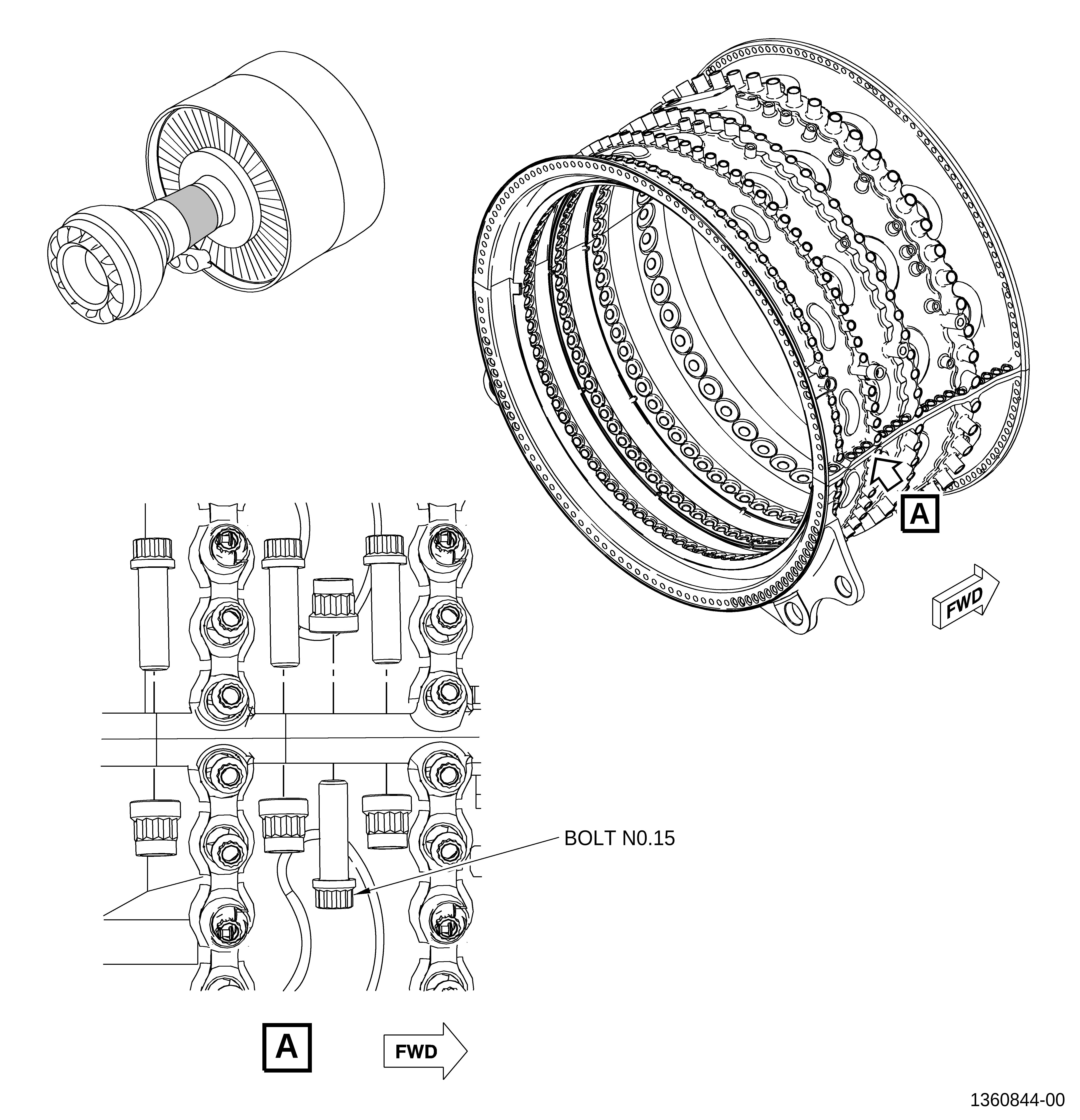
| (4) | Remove the self-locking nut and bolt from the No. 15 bolt hole on the 3:00 o'clock position (ALF) of the HPC stator assembly splitline flange. Refer to Figure 2. |
| NOTE: |
|
| (5) | Inspect the bolt and self-locking nut. Refer to the GEnx-1B CIR, 72-00-00, INSPECTION 001. Discard if necessary. |
| (6) | Apply a thin layer of thread lubricant (C02-058) to the thread and surface faces of the new or removed bolt and self-locking nut. |
| (7) | Install the new or removed bolt and self-locking nut upside down in the No. 15 bolt hole. Refer to Figure 3, Figure 4, and do as follows: |
| (a) | Install the No. 15 bolt from the down to up side of the split flange. |
| (b) | Hand tighten the self-locking nut until it is seated on the face of the split flange. |
| (c) | Torque the self-locking nut to 552-648 lb in (62.4-73.2 Nm). |
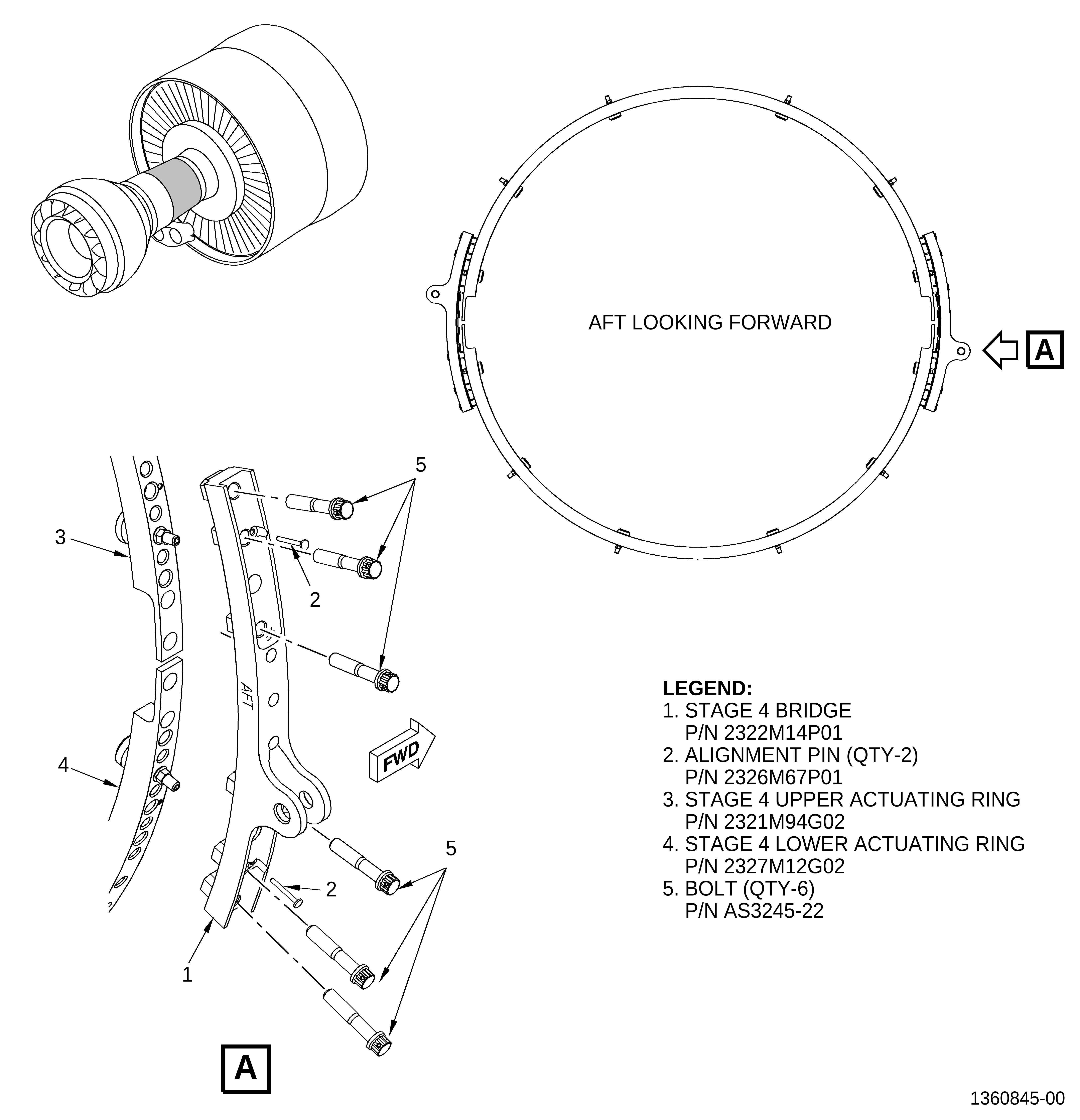
| (8) | Install the stage 4 bridge (1, Figure 5) on the stage 4 upper actuating ring (3) and stage 4 lower actuating ring (4). Refer to Figure 5 and do as follows: |
| (a) | Make sure that the lever pin bushings (bushings) are installed correctly in the stage 4 bridge (1). |
| (b) | Make sure that the "AFT" mark on the stage 4 bridge (1) points aft. |
| (c) | Find the four stage 4 lever arms that are between the stage 4 actuating rings that will insert directly into the stage 4 bridge. Refer to Figure 6. |
| (d) | Align the four stage 4 lever arms and alignment pins to match the holes in the stage 4 bridge. Refer to Figure 6. |
| (e) | Install the stage 4 bridge on the four lever arms and alignment pins on the stage 4 actuating rings. Refer to Figure 6. |
| (f) | Install two alignment pins (2, Figure 5) in the two holes on the stage 4 upper actuating ring (3) and stage 4 lower actuating ring (4). |
| (g) | Attach the stage 4 bridge (1) to the stage 4 upper actuating ring (3) and stage 4 lower actuating ring (4) with six bolts (5). Tighten the bolts (5) hand-tight. |
| (h) | Torque the six bolts (5) on the stage 4 bridge (1) to 235-275 lb in. (26.6-31.1 Nm). |
| (i) | Safety the bolts with safety cable (C10-143). |
| (9) | Install the turnbuckle body into the stage 4 bridge on the 3:00 o'clock position (ALF) of the HPC stator assembly. Attach the turnbuckle body with an aft-facing bolt and self-locking nut. |
| (a) | Torque the self-locking nut to 460-540 lb in. (52.0-61.0 Nm). |
| C. | Assembly |
| (1) | Install the main body heat shield P/N 2343M77G02. Refer to the GEnx-1B, 72-00-02, ASSEMBLY 004. |