| GEnx-1B SERVICE BULLETIN - 72-0083 R01 | Revised: 08/05/2014 | |
| SB 72-0083 R01 ENGINE - General (72-00-00) - Introduction of Integrated Core Water Wash System | Issued: 07/26/2012 | |
| GEnx-1B SERVICE BULLETIN - 72-0083 R01 | Revised: 08/05/2014 | |
| SB 72-0083 R01 ENGINE - General (72-00-00) - Introduction of Integrated Core Water Wash System | Issued: 07/26/2012 | |
| GE PROPRIETARY INFORMATION | |
| The information contained in this document is GE proprietary information and is disclosed in confidence. It is the property of GE and shall not be used, disclosed to others or reproduced without the express written consent of GE, including, but without limitation, it is not to be used in the creation, manufacture, development, or derivation of any repairs, modifications, spare parts, designs, or configuration changes or to obtain FAA or any other government or regulatory approval to do so. If consent is given for reproduction in whole or in part, this notice and the notice set forth on each page of this document shall appear in any such reproduction in whole or in part. | |
| This technical data is considered EAR controlled pursuant to 15 CFR Parts 730-774 respectively. Transfer of this data by any means to a Non-US Person, whether in the United States or abroad, without the proper U.S. Government authorization (e.g., License, exemption, NLR, etc.), is strictly prohibited. | |
| Copyright (2014) General Electric Company, U.S.A. |
| TRANSMITTAL INFORMATION |
| REVISION 1 TO SERVICE BULLETIN 72-0083 |
| Revision 1 is issued to update paragraphs 2., MATERIAL INFORMATION and 3., ACCOMPLISHMENT INSTRUCTIONS . |
| The original was issued July 26, 2012. Revision bars in the left margin identify changes. |
| 1. | PLANNING INFORMATION |
| A. | Effectivity |
|
| This Service Bulletin is applicable to all GEnx-1B engines. |
| The core wash kit P/N 738L340G01 is affected by this Service Bulletin. |
| B. | Description |
| This Service Bulletin provides instructions to install the core wash kit and releases new hardware for the core water wash system. |
| C. | Compliance |
| Category 7 |
| GE recommends that you do this Service Bulletin at customer's convenience. |
| NOTE: |
|
| D. | Concurrent Requirements |
| None. |
| E. | Reason |
| (1) | Objective: |
| To introduce new parts. |
| (2) | Condition: |
| To ease maintenance activity while performing core water wash. |
| (3) | Cause: |
| The existing core water wash procedure requires additional water lances to hook around the booster inlet. |
| (4) | Improvement: |
| The new core water wash system introduces water directly into the core via injectors mounted on the fan hub frame. |
| (5) | Substantiation: |
| Substantiation is by comparative analysis and test. |
| F. | Approval |
| This Service Bulletin has been reviewed by the FAA and the repair(s) and modification(s) herein comply with the applicable Federal Aviation Regulations and are FAA APPROVED for installation in the model(s) listed in this Service Bulletin. |
| G. | Manpower |
| After you get access to the core and fan hub frame, you will need approximately 14 man-hours for each engine. |
| H. | Weight and Balance |
| Weight and balance are not changed. |
| I. | References (Use the latest version of these documents) |
| GEK 9250, Commercial Engine Standard Practices Manual (SPM) |
| GEK 112851, GEnx-1B Engine Manual (EM) |
| GEK 112862, GEnx-1B Cleaning, Inspection, and Repair Manual (CIR) |
| GEK 112864, GEnx-1B Engine Illustrated Parts Catalog (EIPC) |
| GEnx-1B Boeing 787 Aircraft Maintenance Manual (AMM) |
| NOTE: |
|
| J. | Publications Affected |
| GEK 112851, GEnx-1B Engine Manual (EM) |
| GEK 112862, GEnx-1B Cleaning, Inspection, and Repair Manual (CIR) |
| GEK 112864, GEnx-1B Engine Illustrated Parts Catalog (EIPC) |
| GEnx-1B Boeing 787 Aircraft Maintenance Manual (AMM) |
| K. | Interchangeability |
| Interchangeable as a set. |
| L. | Software Accomplishment Summary |
| Not applicable. |
| 2. | MATERIAL INFORMATION |
| A. | Material - Price and Availability |
| (1) | Parts necessary to do this Service Bulletin: |
|
| NOTE: |
|
| (2) | Other Spare Parts: |
|
| *Part not supplied by GE Engine Services Distribution L.L.C. Procure through local purchase. |
| NP = Not Provisioned |
| NOTE: |
|
| (3) | Consumables: |
|
| B. | Industry Support Information |
| Contact your Customer Support Manager (CSM) for industry Support information. |
| C. | Configuration Chart |
|
| Operation Codes AD=Add RM=Remains |
| Change Code 5=Qualified interchangeability. Refer to paragraph 1.K., Interchangeability. |
| Support Code None. |
| D. | Parts Disposition |
| None. |
| E. | Tooling - Price and Availability |
| None. |
| 3. | ACCOMPLISHMENT INSTRUCTIONS |
| A. | General |
| NOTE: |
|
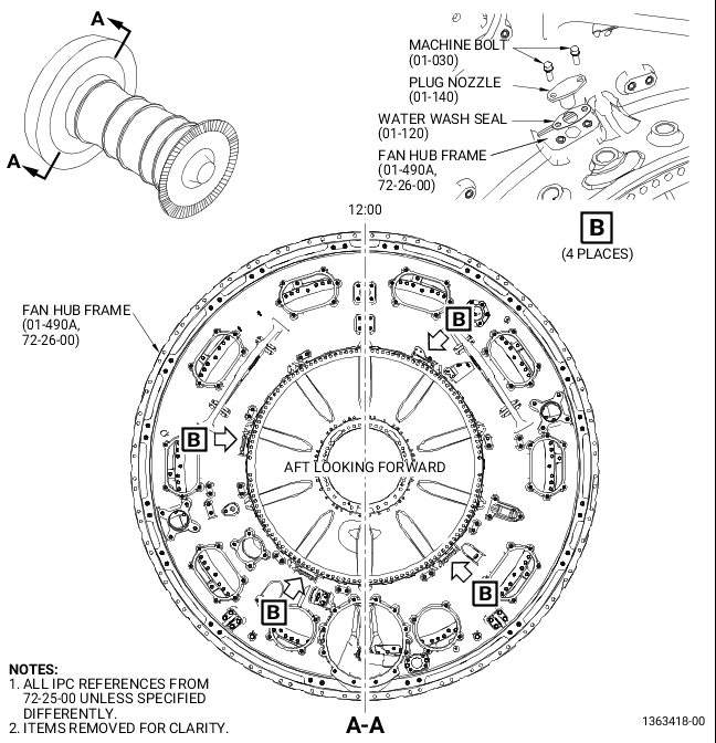
| (1) | Remove the plug nozzles (01-140, 72-25-00, Figure 1) from the fan hub frame (01-490A, 72-26-00) as follows: |
| (a) | Loosen and remove the eight machine bolts (01-030, 72-25-00). |
| (b) | Remove the four plug nozzles (01-140). |
| (c) | Remove the four water wash seals (01-120). |
| NOTE: |
|
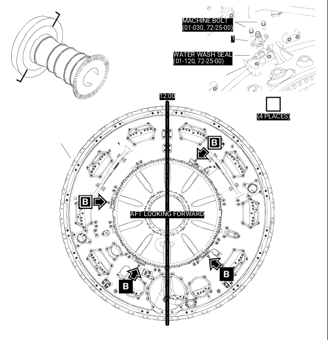
| (2) | Install the core wash nozzles (1, Figure 2) on the fan hub frame (01-490A, 72-26-00) as follows: |
| (a) | Install the water wash seals (01-120, 72-25-00) removed in step 3.A.(1)(c) on the core wash nozzles (1). |
| (b) | Apply C02-058 thread lubricating to the eight machine bolts (01-030, 72-25-00). |
| (c) | Attach the remaining three core wash nozzles (1) on the fan hub frame (01-490A, 72-26-00) with the six machine bolts (01-030, 72-25-00). |
| (d) | Torque all the machine bolts (01-030) to 51-59 lb in. (5.8-6.7 N.m). |
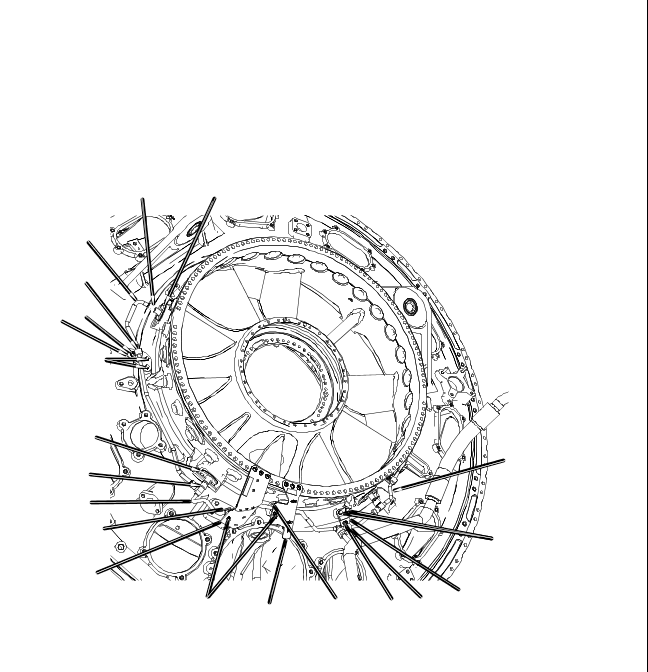
| (3) | Install the water wash support brackets as follows: |
| (a) | Remove the machine bolts (01-020, 72-25-00, Figure 3). |
| (b) | Apply C02-058 thread lubricating to the machine bolts (01-020). |
| (c) | Attach the support bracket (1) with two machine bolts (01-020) at the 1:00, 2:00, and 8:00 o'clock position aft looking forward (ALF) on the fan hub frame (01-490A, 72-26-00). |
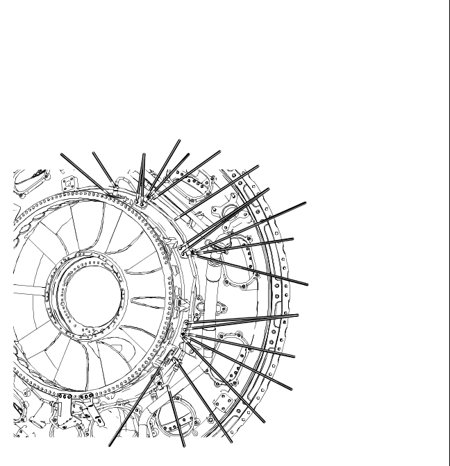
| (d) | Attach the support bracket (2, Figure 4) with two machine bolts (01-020, 72-25-00, Figure 3) at the 4:00 o'clock position ALF on the fan hub frame (01-490A, 72-26-00). |
| (e) | Attach the support bracket (2) with two machine bolts (01-020, 72-25-00) at the 5:00 o'clock position ALF on the fan hub frame (01-490A, 72-26-00). |
| (f) | Torque the machine bolts (01-020, 72-25-00) to 32-38 lb in. (3.6-4.3 N.m). |
| (4) | Install the core wash manifold (9, Figure 4) on the fan hub frame (01-490A, 72-26-00) as follows: |
| (a) | Connect the core wash manifold (9) to two core wash nozzles (6), tighten B-nuts hand tight. |
| (b) | Attach the core wash manifold (9) to the support brackets (1) and (2) with three cushioned loop clamps (5) and three machine bolts (7). |
| (c) | Torque the machine bolts (7) to 32-38 lb in. (3.6-4.3 N.m). |
| (d) | Torque the B-nuts of the core wash manifold (9) to 262-308 lb in. (29.6-34.8 N.m). |
| (5) | Install the core wash manifold (9, Figure 3) on the fan hub frame (01-490A, 72-26-00) as follows: |
| (a) | Connect the core wash manifold (9) to the core wash manifold (4) and to the core wash nozzle (6), tighten B-nuts hand tight. |
| (b) | Attach the core wash manifold (9) to the support bracket (2), support bracket (25-450, 72-00-02), and support bracket (25-430, 72-00-02) with three cushioned loop clamps (5) and the machine bolts (7). |
| (c) | Torque the machine bolts (7) to 32-38 lb in. (3.6-4.3 N.m). |
| (d) | Torque the B-nuts of the core wash manifold (9) to 262-308 lb in. (29.6-34.8 N.m). |
| (6) | Install the core wash water tube (3, Figure 3) on the fan hub frame (01-490A, 72-26-00) as follows: |
| (a) | Connect the core wash water tube (3) to the core wash manifold (9) and to the core wash nozzle (6), tighten B-nuts hand tight. |
| (b) | Attach the core wash water tube (3) to the support bracket (1) with one cushioned loop clamp (5) and one machine bolt (7). |
| (c) | Torque the machine bolt (7) to 32-38 lb in. (3.6-4.3 N.m). |
| (d) | Torque the B-nuts of the core wash water tube (3) to 262-308 lb in. (29.6-34.8 N.m). |
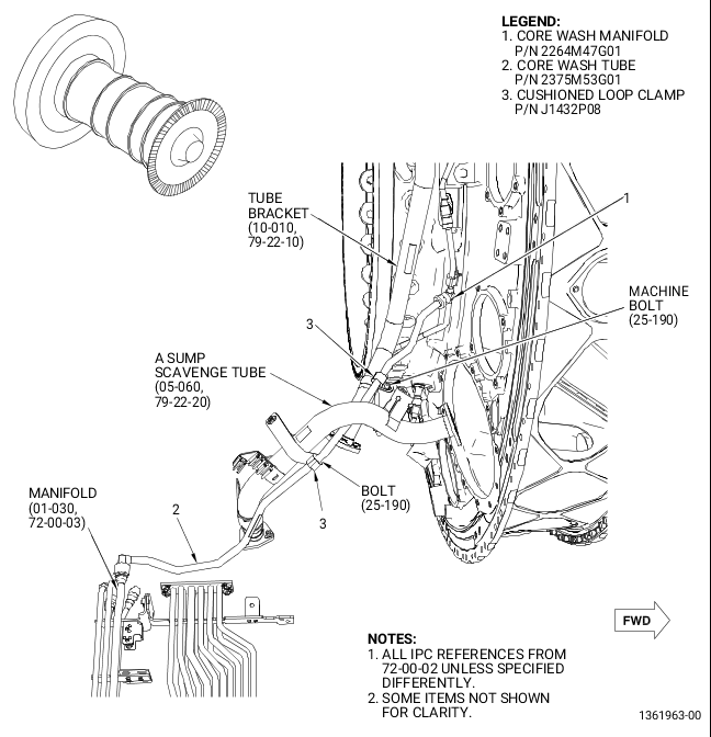
| (7) | Install the core wash tube (2, Figure 5) on the fan hub frame (01-490A, 72-26-00) as follows: |
| (a) | Remove the tube cap (01-320, 72-00-03) from the tube in aft drain upper manifold (manifold) (01-030, 72-00-03). |
| (b) | Connect the core wash tube (2) to the core wash water tube (1), tighten B-nuts hand tight. |
| (c) | Connect the core wash tube (2) to the manifold (01-030, 72-00-03), tighten B-nuts hand tight. |
| (d) | Attach the core wash tube (2) to the tube bracket (10-010, 79-22-10) with a cushioned loop clamp (3) and a machine bolt (25-190, 72-00-02). |
| (e) | Torque the machine bolt (25-190) to 51-59 lb in. (5.8-6.7 N.m). |
| (f) | Attach the core wash tube (2) to the A sump scavenge tube (05-060, 79-22-20) with a cushioned loop clamp (3) and a machine bolt (25-190, 72-00-02). |
| (g) | Torque the machine bolt (25-190) to 51-59 lb in. (5.8-6.7 N.m). |
| (h) | Torque the B-nuts of the core wash tube (2) to 262-308 lb in. (29.6-34.8 N.m). |
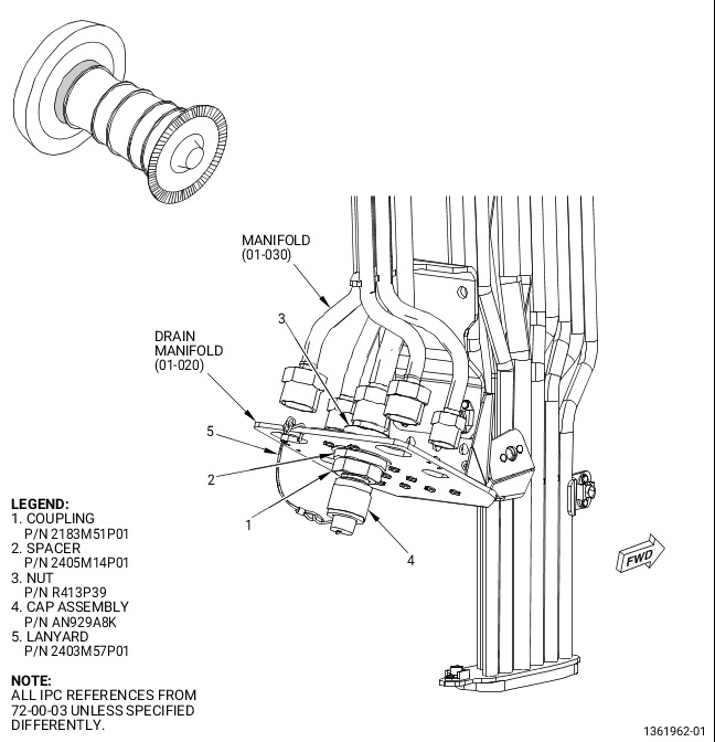
| (8) | Install the coupling (1, Figure 6) on the lower bifurcation-drain manifold (01-020, 72-00-03) as follows: |
| (a) | Remove the plug (01-350, 72-00-03). |
| (b) | Insert the spacer (2) on the coupling (1). |
| (c) | Apply C02-058 thread lubricating to the male threads and bearing surfaces of the coupling (1). |
| (d) | Insert the coupling (1) through the lower bifurcation-drain manifold (01-020, 72-00-03) and secure with the nut (3) hand tight. |
| (e) | Connect the manifold (01-030, 72-00-03) to the coupling (1) hand tight. |
| (f) | Torque the nut (3) to 262-308 lb in. (29.6-34.8 N.m). |
| (g) | Use C10-143 safety cable or safety wire to firmly attach the nut. |
| (h) | Torque the B-nut of the manifold (01-030, 72-00-03) to 262-308 lb in. (29.6-34.8 N.m). |
| (i) | Apply C02-058 thread lubricating to the male threads of the coupling (1). Install the cap assembly (4) and torque to 262-308 lb in. (29.6-34.8 N.m). |
| (j) | Attach the lanyard (5) to the drain manifold (01-020, 72-00-03) and cap assembly (4). |