| GEnx-1B SERVICE BULLETIN - 72-0088 R01 | Revised: 09/23/2013 | |
| SB 72-0088 R01 ENGINE - Propulsor Module Assembly (72-00-00) - Introduction of New VSFG Power Feeder Harnesses | Issued: 10/16/2012 | |
| GEnx-1B SERVICE BULLETIN - 72-0088 R01 | Revised: 09/23/2013 | |
| SB 72-0088 R01 ENGINE - Propulsor Module Assembly (72-00-00) - Introduction of New VSFG Power Feeder Harnesses | Issued: 10/16/2012 | |
| GE PROPRIETARY INFORMATION | |
| The information contained in this document is GE proprietary information and is disclosed in confidence. It is the property of GE and shall not be used, disclosed to others or reproduced without the express written consent of GE, including, but without limitation, it is not to be used in the creation, manufacture, development, or derivation of any repairs, modifications, spare parts, designs, or configuration changes or to obtain FAA or any other government or regulatory approval to do so. If consent is given for reproduction in whole or in part, this notice and the notice set forth on each page of this document shall appear in any such reproduction in whole or in part. | |
| This technical data is considered EAR controlled pursuant to 15 CFR Parts 730-774 respectively. Transfer of this data by any means to a Non-US Person, whether in the United States or abroad, without the proper U.S. Government authorization (e.g., License, exemption, NLR, etc.), is strictly prohibited. | |
| Copyright (2013) General Electric Company, U.S.A. |
| TRANSMITTAL INFORMATION |
| REVISION 1 TO SERVICE BULLETIN 72-0088 |
| Revision 1 is issued to update paragraphs 1.I., References , 2., MATERIAL INFORMATION , and 3.,ACCOMPLISHMENT INSTRUCTIONS . |
| The original was issued on the October 16, 2012. Revision bars in the left margin identify changes. |
| 1. | PLANNING INFORMATION |
| A. | Effectivity |
|
| This Service Bulletin is applicable to these GEnx-1B engines: |
| • |
|
| This Service Bulletin has been introduced in production to these GEnx-1B engines: |
| • |
|
| All engines retrofitted at Boeing prior to entry into service. |
| The old VFSG1 power feeder harness (power feeder cable) P/N 506002-3, VFSG2 power feeder harness (power feeder cable) P/N 506003-3, and associated hardware are affected by this Service Bulletin. |
| B. | Description |
| This Service Bulletin releases a new power feeder cable P/N 513392-1, power feeder cable P/N 513397-1, and associated hardware. |
| C. | Compliance |
| Category 9 |
| Information only. |
| All engines were upgraded before delivery. |
| NOTE: |
|
| D. | Concurrent Requirements |
| None. |
| E. | Reason |
| (1) | Objective: |
| To introduce new parts. |
| (2) | Condition: |
| Low level of EMI/HIRF protection. |
| (3) | Cause: |
| The initial designed power feeder harness did not meet the aircraft level EMI/HIRF protection requirements. |
| (4) | Improvement: |
| The new harness provides additional shielding and grounding path for the engine installation. |
| (5) | Substantiation: |
| Substantiation is by analysis and test. |
| F. | Approval |
| This Service Bulletin has been reviewed by the FAA and the repair(s) and modification(s) herein comply with the applicable Federal Aviation Regulations and are FAA APPROVED for installation in the model(s) listed in this Service Bulletin. |
| G. | Manpower |
| No additional man-hours are required to comply with this Service Bulletin. |
| H. | Weight and Balance |
| The complete compliance with this Service Bulletin increases weight by 6.5 lb (2.9 kg). |
| I. | References (Use the latest version of these documents) |
| GEK 9250, Commercial Engine Standard Practices Manual (SPM) |
| GEK 112851, GEnx-1B Engine Manual (EM) |
| GEK 112864, GEnx-1B Engine Illustrated Parts Catalog (EIPC) |
| GEK 114013, GEnx-1B Power Feeder Harness, Component Maintenance Manuals (CMM) |
| GEnx-1B, Boeing 787 Aircraft Maintenance Manual (AMM): |
| • |
|
| • |
|
| NOTE: |
|
| J. | Publications Affected |
| GEK 112851, GEnx-1B Engine Manual (EM) |
| GEK 112864, GEnx-1B Engine Illustrated Parts Catalog (EIPC) |
| GEK 114013, GEnx-1B Power Feeder Harness, CMM |
| K. | Interchangeability |
| All parts must be incorporated concurrently. |
| L. | Software Accomplishment Summary |
| Not applicable. |
| 2. | MATERIAL INFORMATION |
| A. | Material - Price and Availability |
| (1) | Parts necessary to do this Service Bulletin: |
|
| *Part not supplied by GE Engine Services Distribution L.L.C. To procure parts, contact the following: |
| Unison Industries Inc. |
| 7575 Baymeadows Way |
| Jacksonville, FL 32256 |
| U.S.A. |
| NP = Not Provisioned |
| NOTE: |
|
| (2) | Other Spare Parts: |
| None. |
| (3) | Consumables: |
|
| B. | Industry Support Information |
| None. |
| C. | Configuration Chart |
|
| Operation Codes AD=Add RE=Replace RM=Remains RW=Rework DE=Delete QTC=Quantity Change |
| Change Code 5=Qualified interchangeability. Refer to paragraph 1.K., Interchangeability |
| Support Code A=Old parts will no longer be supplied. |
| D. | Parts Disposition |
| None. |
| E. | Tooling - Price and Availability |
| None. |
| 3. | ACCOMPLISHMENT INSTRUCTIONS |
| A. | Power Feeder Cables Removal |
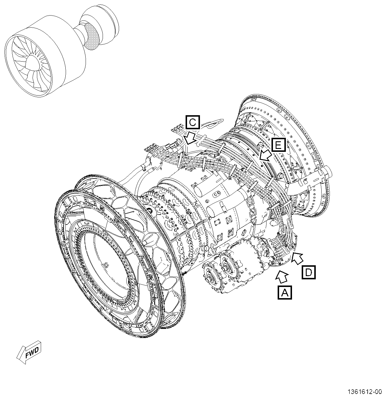
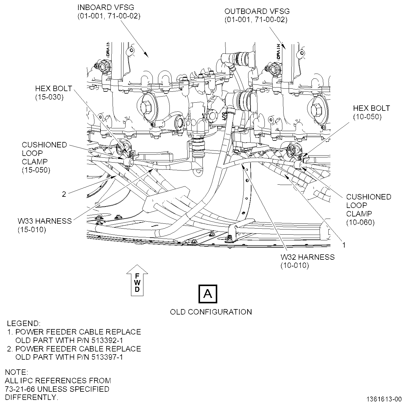
| (1) | Removal instructions for the power feeder cables (1 and 2, Figure 1, Sheet 2) have not changed. Refer to the GEnx-1B EM, 72-00-02, DISASSEMBLY 001. |
| B. | Power Feeder Cables Installation |
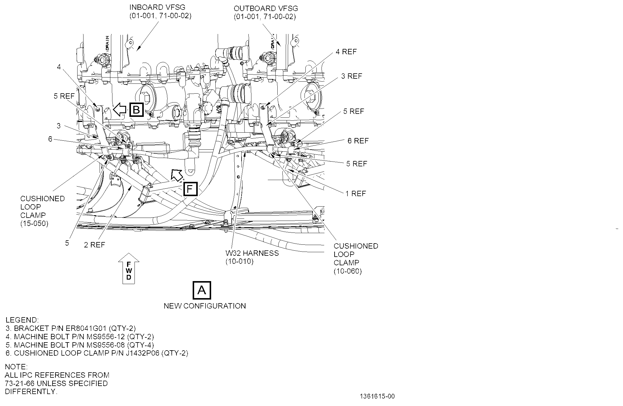
| (1) | Install the bracket (3, Figure 1, Sheet 3) in the inboard variable frequency starter generator (VFSG) (01-001, 71-00-02) as follows: |
| (a) | Remove the hex bolt (15-030, 73-21-66, Sheet 2) that attaches the W33 harness (15-010) to the inboard VFSG with a cushioned loop clamp (15-050). Do not remove cushioned loop clamp (15-050). |
| (b) | Inspect the two mounting bosses on the VFSG for full alodine coating as follows: |
| 1 | Do a touch up of the alodine with C03-092 coating class 3 for electrical conductivity per manufacturers instructions. |
| WARNING: |
|
| 2 | If no touch up is necessary, clean the contact surfaces of the mounting bosses and the bracket (3, Sheet 3) with C04-035 isopropyl alcohol. |
| (c) | Attach the bracket (3) with one machine bolt (4) on the inboard VFSG. Hand-tighten the machine bolt (4). |
| (d) | Move the cushioned loop clamp (15-050) on the W33 harness into position on the bracket (3). |
| (e) | Align the boltholes of the bracket (3) with the threaded boss on the inboard VFSG and install one machine bolt (5) through the cushioned loop clamp (15-050) and bracket (3). Hand-tighten the machine bolt (5). |
| (f) | Apply C01-006 RTV 103 or RTV 106 in 360 degrees under the bolt heads of machine bolts (4 and 5). |
| (g) | Torque the machine bolts (4 and 5) to 32-38 lb in. (3.6-4.3 Nm). |
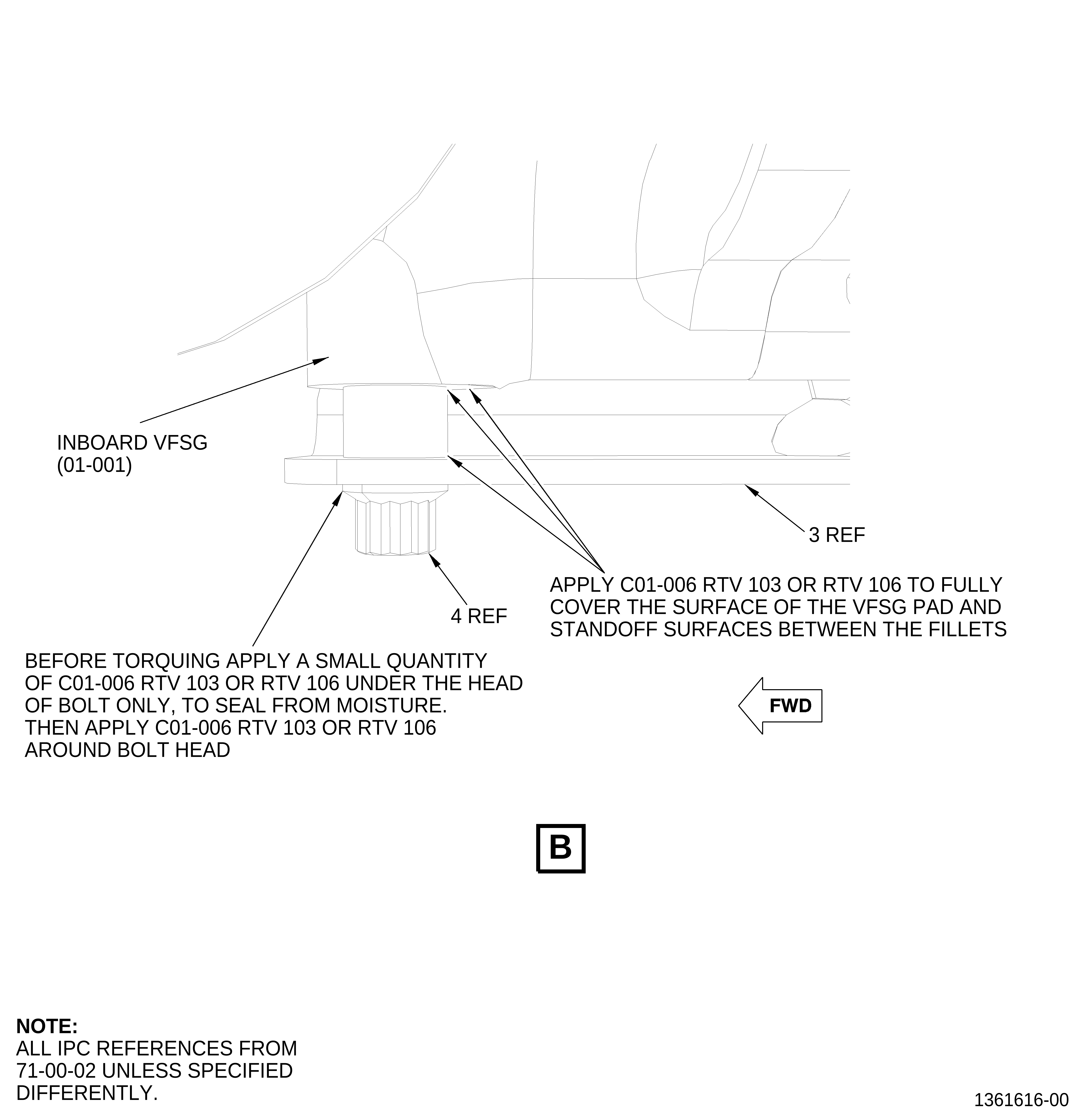
| (h) | Apply C01-006 RTV 103 or RTV 106 to seal around the bolt heads of machine bolts (4 and 5). On the machine bolt (4) interface apply C01-006 RTV 103 or RTV 106 to the bracket spacer and VFSG bosses to fully cover the VFSG bosses. Refer to Figure 1, Sheet 4. |
| (i) | Attach the W33 harness with one cushioned loop clamp (6, Sheet 3) and one machine bolt (5) to the inboard VFSG. |
| (j) | Torque the machine bolt (5) to 32-38 lb in. (3.6-4.3 Nm). |
| (2) | Install the bracket (3) in the outboard VFSG (01-001, 71-00-02) as follows: |
| (a) | Remove the hex bolt (10-050, 73-21-66, Sheet 2) that attaches the W32 harness (10-010) to the outboard VFSG with a cushioned loop clamp (10-060). Do not remove cushioned loop clamp (10-060). |
| (b) | Inspect the two mounting bosses on the VFSG for full alodine coating as follows: |
| 1 | Do a touch up of the alodine with C03-092 coating class 3 for electrical conductivity per manufacturers instructions. |
| WARNING: |
|
| 2 | If no touch up is necessary, clean the contact surfaces of the mounting bosses and the bracket (3, Sheet 3) with C04-035 isopropyl alcohol. |
| (c) | Attach the bracket (3) with one machine bolt (4) on the outboard VFSG. Hand-tighten the machine bolt (4). |
| (d) | Move the cushioned loop clamp (10-060) on the W32 harness into position on the bracket (3). |
| (e) | Align the boltholes of the bracket (3) with the threaded boss on the outboard VFSG and install one machine bolt (5) through the cushioned loop clamp (10-060) and bracket (3). Hand-tighten the machine bolt (5). |
| (f) | Apply C01-006 RTV 103 or RTV 106 in 360 degrees under the bolt heads of machine bolts (4 and 5). |
| (g) | Torque the machine bolts (4 and 5) to 32-38 lb in. (3.6-4.3 Nm). |
| (h) | Apply C01-006 RTV 103 or RTV 106 to seal around the bolt heads of machine bolts (4 and 5). On the machine bolt (4) interface apply C01-006 RTV 103 or RTV 106 to the bracket spacer and VFSG bosses to fully cover the VFSG bosses. Refer to Figure 1, Sheet 4. |
| (i) | Attach the W32 harness with one cushioned loop clamp (6, Sheet 3) and one machine bolt (5) to the outboard VFSG. |
| (j) | Torque the machine bolt (5) to 32-38 lb in. (3.6-4.3 Nm). |
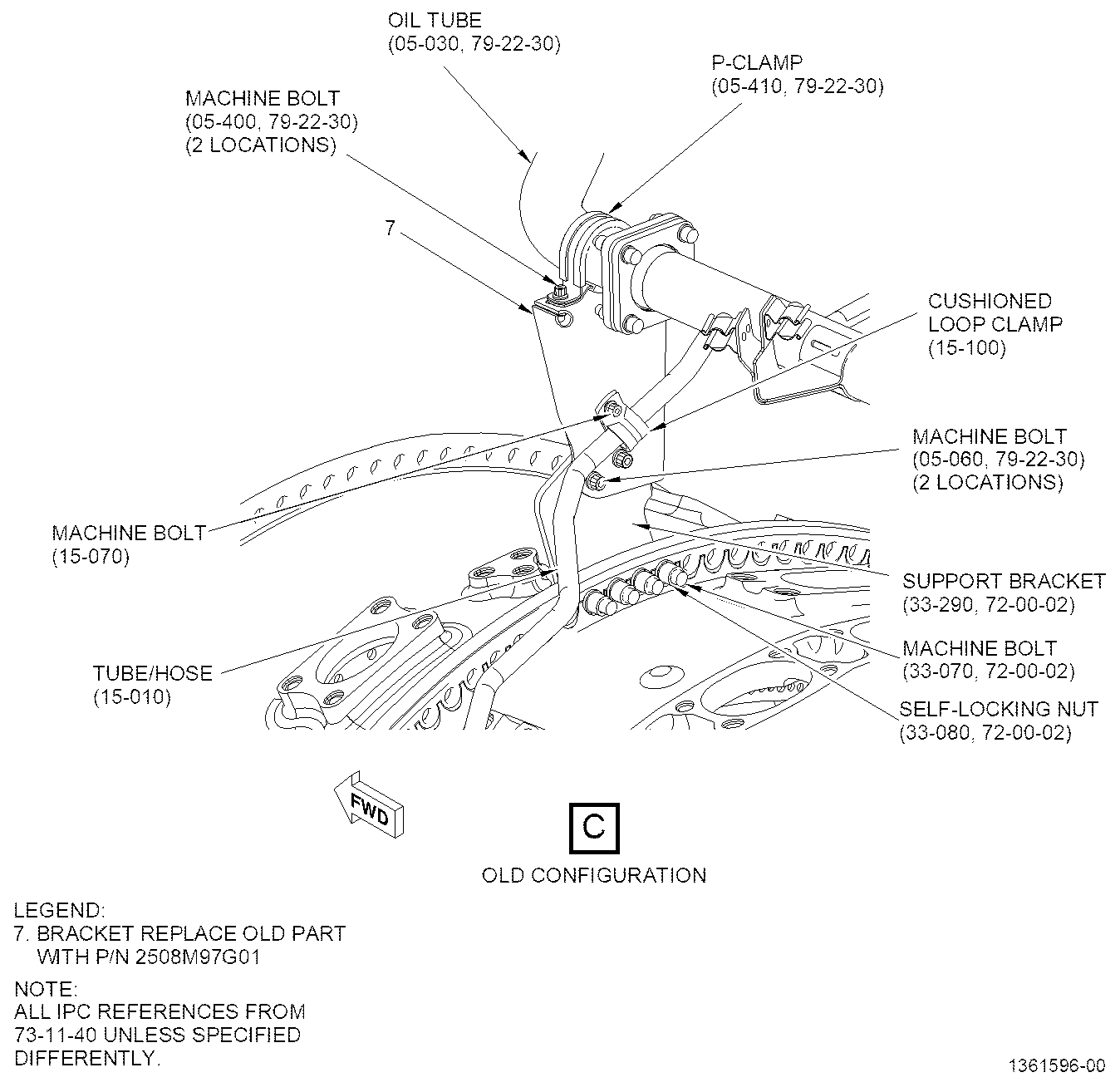
| (3) | Replace the oil tube bracket (bracket) (7, Sheet 5) as follows: |
| (a) | Remove the machine bolt (15-070, 73-11-40) that attaches the signal fuel tube/hose (tube/hose) (15-010) to the bracket (7) with a cushioned loop clamp (15-100). Do not remove the cushioned loop clamp (15-100) from the tube/hose. |
| (b) | Remove two machine bolts (05-400, 79-22-30) that attach the oil tube (05-030) to the bracket (7) with a P-clamp (05-410). Do not remove the P-clamp (05-410) from the oil tube. |
| (c) | Remove two machine bolts (05-060) that attach the bracket (7) to the support bracket (33-290, 72-00-02). |
| (d) | Remove the bracket (7) from the engine. |
| WARNING: |
|
| (e) | Clean the areas of the new bracket (7, Sheet 6) and support bracket (33-290), with C04-035 isopropyl alcohol and a C10-182 lint-free cloth or equivalent. |
| (f) | Put the bracket (7) on the support bracket (33-290) and align the boltholes. |
| (g) | Install two machine bolts (05-060, 79-22-30) through the bracket (7) and into the nut plates on the support bracket (33-290, 72-00-02). |
| (h) | Torque the machine bolts (05-060, 79-22-30) to 106-124 lb in. (12.0-14.0 Nm). |
| (i) | Attach the oil tube with the P-clamp (05-410) and two machine bolts (05-400) to the bracket (7). |
| (j) | Torque the machine bolts (05-400) to 51-59 lb in. (5.8-6.7 Nm). |
| (k) | Align the cushioned loop clamp (15-100, 73-11-40) attached to the tube/hose with the nut plate on the bracket (7) and install the machine bolt (15-070). |
| (l) | Torque the machine bolt (15-070) to 32-38 lb in. (3.6-4.3 Nm). |
| (4) | Attach the ground straps (05-430, 71-00-00) and (05-440), (Figure 1, Sheet 6) to the bracket (7) as follows: |
| WARNING: |
|
| (a) | Clean the surfaces of the ground strap lugs and face of the bracket (7) with C04-035 isopropyl alcohol and a C10-182 lint-free cloth or equivalent. |
| (b) | Attach the ground straps (05-430) and (05-440) leads to the bracket (7) with two machine bolts (bolt) (05-420) . |
| (c) | After installing the bolts (05-420) that attach the ground straps (05-430) and (05-440) to the bracket (7), put the ground straps so they point toward the left side of the engine aft locking forward (ALF) and hold in place while torquing. |
| (d) | Torque the bolts (05-420) to 106-124 lb in. (12.0-14.0 Nm). |
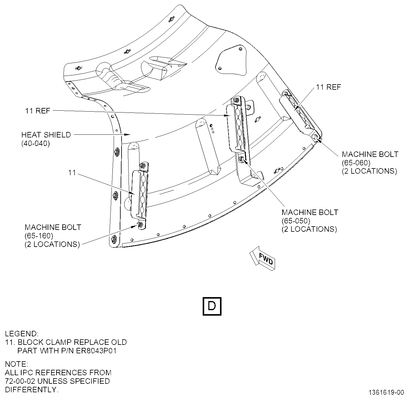
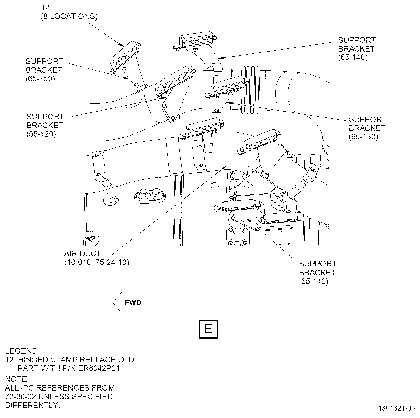
| (5) | Install the block clamps (11, Sheet 7), hinged clamps (12, Sheet 8), and power feeder cables (1 and 2, Sheet 2). Refer to the GEnx-1B EM, 72-00-02, ASSEMBLY 006 and GEnx-1B Boeing 787 AMM DMC-B787-A-24-21-05-01B-720A-A and DMC-B787-A-24-21-05-02B-720A-A with the following exceptions: |
| WARNING: |
|
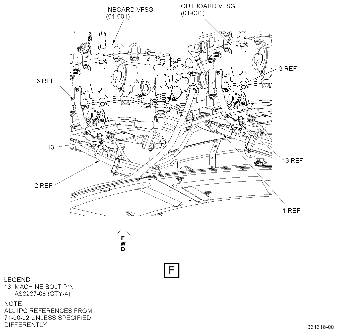
| (a) | Clean the surfaces of the power feeder cable ground lug and surfaces on the brackets (3, Sheet 9) with C04-035 isopropyl alcohol and a C10-182 lint-free cloth or equivalent. |
| (b) | Connect the VFSG end ground lugs to the brackets (3) with two machine bolts (13) on each bracket (3). |
| (c) | Torque the machine bolts (13) to 106-124 lb in. (12.0-14.0 Nm). |
| (6) | Measure the resistance of the electrical bonding between brackets (3, Sheet 3) and VFSG (01-001, 71-00-02) to make sure that it measures less than 2.5 milliohms. |
| (7) | Measure the resistance of the electrical bonding between the bracket (33-290, 72-00-02, Sheet 6) and the engine case to make sure that it measures less than 2.5 milliohms. |
| (8) | Measure the resistance of the electrical bonding of bracket (7) to support bracket (33-290) to make sure that it measures less than 2.5 milliohms. |
| (9) | Measure the resistance of the electrical bonding of ground straps (05-430, 71-00-00) and (05-440) that are attached to the bracket (7) to make sure that it measures less than 2.5 milliohms. |
| (10) | Measure the resistance of the electrical bonding between the bolts (13, Sheet 9) in the ground lugs to the brackets (3) to make sure that it measures less than 2.5 milliohms. |
| (11) | If the resistance level is higher than 2.5 milliohms for any of the requested electrical bonding checks, do as follows: |
| (a) | Refer to the SPM, 70-10-00, ASSEMBLY AND DISASSEMBLY TECHNIQUES. |
| (b) | Disassemble the affected mating surfaces that did not pass the electrical bonding check. |
| WARNING: |
|
| (c) | Clean the mating surfaces with C04-035 isopropyl alcohol and a C10-182 lint-free cloth or equivalent. |
| (d) | Assemble the affected mating surfaces again and apply the specified torque. |
| (e) | Measure the resistance of the electrical bonding to make sure that it is lower than 2.5 milliohms. |