| GEnx-1B SERVICE BULLETIN - 72-0126 R02 | Revised: 08/25/2014 | |
| SB 72-0126 R02 AIR - 7th Stage HPT ACC Manifolds (75-24-30) - Air Tube Redesign and Bracket Deletion | Issued: 02/07/2013 | |
| GEnx-1B SERVICE BULLETIN - 72-0126 R02 | Revised: 08/25/2014 | |
| SB 72-0126 R02 AIR - 7th Stage HPT ACC Manifolds (75-24-30) - Air Tube Redesign and Bracket Deletion | Issued: 02/07/2013 | |
| GE PROPRIETARY INFORMATION | |
| The information contained in this document is GE proprietary information and is disclosed in confidence. It is the property of GE and shall not be used, disclosed to others or reproduced without the express written consent of GE, including, but without limitation, it is not to be used in the creation, manufacture, development, or derivation of any repairs, modifications, spare parts, designs, or configuration changes or to obtain FAA or any other government or regulatory approval to do so. If consent is given for reproduction in whole or in part, this notice and the notice set forth on each page of this document shall appear in any such reproduction in whole or in part. | |
| This technical data is considered EAR controlled pursuant to 15 CFR Parts 730-774 respectively. Transfer of this data by any means to a Non-US Person, whether in the United States or abroad, without the proper U.S. Government authorization (e.g., License, exemption, NLR, etc.), is strictly prohibited. | |
| Copyright (2014) General Electric Company, U.S.A. |
| TRANSMITTAL INFORMATION |
| REVISION 2 TO SERVICE BULLETIN 72-0126 |
| Revision 2 is issued to update paragraph 1.K., Interchangeability . |
| Revision 1 was issued May 13, 2014. The original was issued February 07, 2013. Revision bars in the left margin identify changes. |
| 1. | PLANNING INFORMATION |
| A. | Effectivity |
|
| This Service Bulletin has been introduced in production to these GEnx-1B engines: |
| • |
|
| These serial numbers are the best available data. |
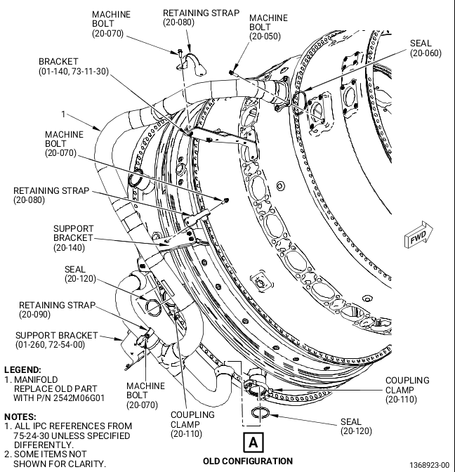
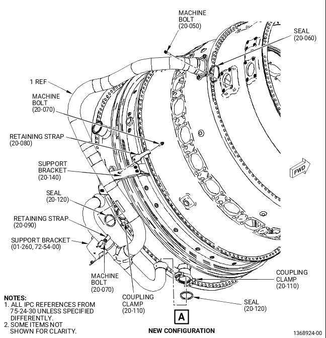
| The HPTC air manifold (manifold) P/N 2448M55G01, 7th stage air support bracket (bracket) 2373M93G01, retaining strap 9134M25P33, and machine bolts AS3237- 08 are affected by this Service Bulletin. |
| B. | Description |
| This Service Bulletin deletes the bracket 2373M93G01, which simplifies the configuration and reduces weight and assembly time. |
| C. | Compliance |
| Category 7 |
| GE recommends that you do this Service Bulletin at customer's convenience/option. |
| NOTE: |
|
| D. | Concurrent Requirements |
| None. |
| E. | Reason |
| (1) | Objective: |
| To introduce a new part and to reduce weight. This revision incorporates the change to the GEnx-1B/P2 configuration, releasing the new combustor diffuser nozzle (CDN) assembly and combustor diffuser assembly to the IPC. |
| (2) | Condition: |
| It was identified that the bracket P/N 2373M93G01 that supports the manifold P/N 2448M55G01 could be optimized. After reviewing, it was demonstrated that the bracket and associated hardware could be eliminated. The manifold is changed to eliminate a wear sleeve at the location where the bracket is eliminated. |
| (3) | Cause: |
| Analysis for potential bracket simplification showed the lack of effectiveness of the bracket, which led to identifying its lack of any significant effect at all. |
| (4) | Improvement: |
| Parts count is reduced by eliminating the bracket and reducing quantities of two machine bolts and one retaining strap. This reduction represents weight savings of 1.5 lb (0.7 kg) per engine. |
| (5) | Substantiation: |
| Substantiation is by analysis and comparative analysis. |
| F. | Approval |
| This Service Bulletin has been reviewed by the FAA and the repair(s) and modification(s) herein comply with the applicable Federal Aviation Regulations and are FAA APPROVED for installation in the model(s) listed in this Service Bulletin. |
| G. | Manpower |
| No additional man-hours are required to comply with this Service Bulletin. |
| H. | Weight and Balance |
| The complete compliance with this Service Bulletin decreases weight by 1.5 lb (0.7 kg). |
| I. | References (Use the latest version of these documents) |
| GEK 112851, GEnx-1B Engine Manual (EM) |
| GEK 112864, GEnx-1B Engine Illustrated Parts Catalog (EIPC) |
| GEnx-1B S/B 72-0161, ENGINE - General (72-00-00) - GEnx-1B/P2 Hardware Release (Propulsor Module) |
| NOTE: |
|
| J. | Publications Affected |
| GEK 112851, GEnx-1B Engine Manual (EM) |
| GEK 112864, GEnx-1B Engine Illustrated Parts Catalog (EIPC) |
| K. | Interchangeability |
| It is allowed to remove the bracket, retaining strap, related machine bolts, and use either air manifold. |
| If the bracket, retaining strap, and related machine bolts are present, the air manifold with wear sleeves is required. |
| L. | Software Accomplishment Summary |
| Not applicable. |
| 2. | MATERIAL INFORMATION |
| A. | Material - Price and Availability |
| (1) | Parts necessary to do this Service Bulletin: |
|
| NOTE: |
|
| (2) | Other Spare Parts: |
|
| *Part not supplied by GE Engine Service Distribution L.L.C. Procure through local purchase. |
| NP=Not Provisioned |
| NOTE: |
|
| (3) | Consumables: |
|
| B. | Industry Support Information |
| None. |
| C. | Configuration Chart |
|
| Operation Codes DE=Delete RE=Replace RM=Remains RW=Rework QTC=Quantity Change |
| Change Code 5=Qualified interchangeability. Refer to paragraph 1.K., Interchangeability. |
| Support Codes B=Old parts will be supplied until all old parts are sold. E=Old parts will be supplied, and can be used at other engine locations. |
| D. | Parts Disposition |
| Use serviceable old parts for engines that have not changed. |
| E. | Tooling - Price and Availability |
| None. |
| 3. | ACCOMPLISHMENT INSTRUCTIONS |
| A. | Removal |
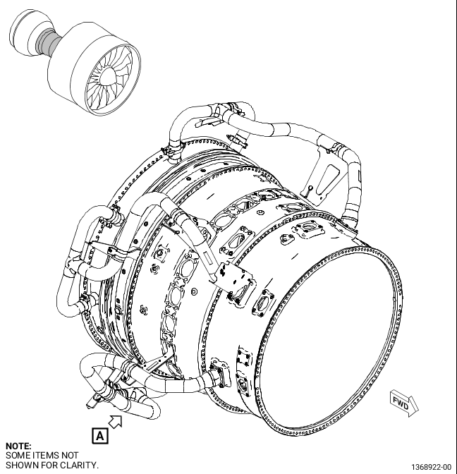
| (1) | Removal instructions for the manifold (1, Figure 1) have not changed. Refer to the GEnx-1B EM, 72-00-02, DISASSEMBLY 003, Subtask 72-00-02-030-456. |
| (2) | Removal instructions for the bracket (01-140, 73-11-30) have not changed. Refer to the GEnx-1B EM, 72-41-00, DISASSEMBLY 001, Subtask 72-41-00-040-024. |
| B. | Installation |
| (1) | Install the new manifold (1, Figure 1) as follows: |
| (a) | Install the metal seal ring (seal) (20-060, 75-24-30) on the forward end of the manifold (1). |
| WARNING: |
|
| NOTE: |
|
| (b) | Install two ring seals (seals) (20-120) on the aft ends of the manifold (1). |
| NOTE: |
|
| (c) | Install the forward end of the manifold (1) on the extension case and the aft ends on the HPT stator case. |
| (d) | Attach the aft ends with coupling clamps (20-110). Install the coupling clamps with the nut pointed aft to the 6:00 o'clock position. |
| (e) | Attach the forward end with four machine bolts (20-050). |
| (f) | Attach the manifold (1) to the support bracket (20-140) with one retaining strap (20-080) and two machine bolts (20-070). |
| (g) | Attach the manifold (1) to the support bracket (01-260, 72-54-00) with one retaining strap (20-090, 75-24-30) and two machine bolts (20-070). |
| (h) | Torque the machine bolts (20-050) in a criss-cross pattern to 106-124 lb in. (12.0-14.0 N.m). |
| (i) | Torque the coupling clamps (20-110) to 60-70 lb in. (6.8-7.9 N.m). |
| (j) | Torque the machine bolts (20-070) to 106-124 lb in. (12.0-14.0 N.m). |