| GEnx-1B SERVICE BULLETIN - 72-0130 R00 | Revised: 03/12/2013 | |
| SB 72-0130 R00 ENGINE - High Pressure Compressor Rotor Assembly (72-31-00) - HPC Rotor Locking Lugs New Design | Issued: 03/12/2013 | |
| GEnx-1B SERVICE BULLETIN - 72-0130 R00 | Revised: 03/12/2013 | |
| SB 72-0130 R00 ENGINE - High Pressure Compressor Rotor Assembly (72-31-00) - HPC Rotor Locking Lugs New Design | Issued: 03/12/2013 | |
| 1. | PLANNING INFORMATION |
| A. | Effectivity |
|
| This Service Bulletin is applicable to all GEnx-1B engines. |
| This Service Bulletin has been introduced in production to these GEnx-1B engines: |
| • |
|
| These serial numbers are the best available data. |
| The locking lugs P/N 2324M77P02, P/N 2324M78P02, P/N 2324M79P02, and P/N 2324M80P02 are affected by this Service Bulletin. |
| B. | Description |
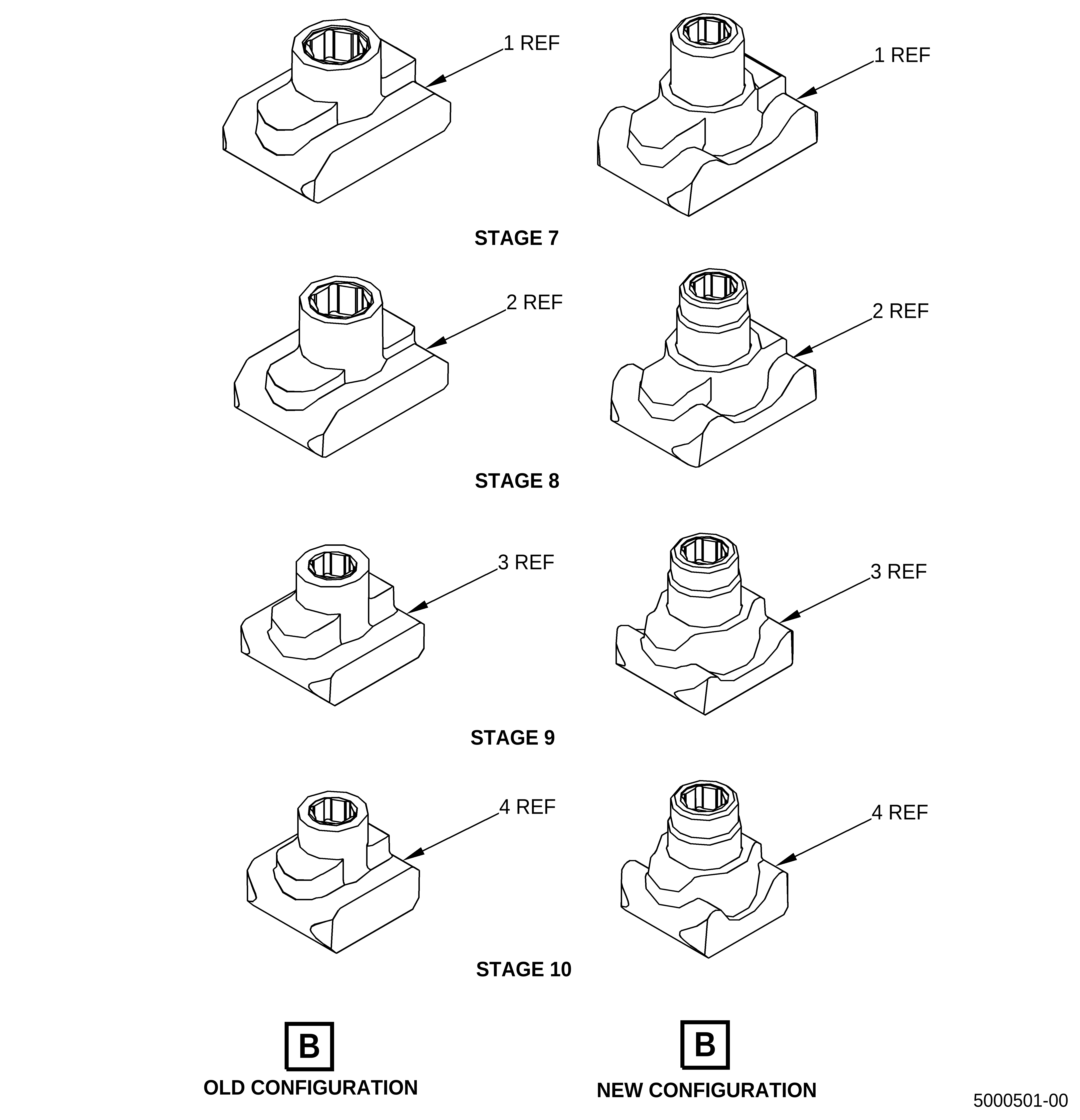
| This Service Bulletin provides new designs for locking lugs P/N 2464M77P02, P/N 2464M78P02, P/N 2464M79P02, and P/N 2464M80P02 for the high pressure compressor (HPC) rotor assembly P/N 2305M51G06 and P/N 2305M51G07. |
| C. | Compliance |
| Category 7 |
| GE recommends that you do this Service Bulletin at customer's option. |
| NOTE: |
|
| D. | Concurrent Requirements |
| None. |
| E. | Reason |
| (1) | Objective: |
| To improve maintainability. |
| (2) | Condition: |
| Current locking lugs P/N 2324M77P02, P/N 2324M78P02, P/N 2324M79P02, and P/N 2324M80P02 have risk of part damage during disassembly process and increased assembly time. |
| (3) | Cause: |
| Current small diameter screws are limited to low torque capability Torx heads, which restricts the installers' ability to assemble and remove the locking lugs P/N 2324M77P02, P/N 2324M78P02, P/N 2324M79P02, and P/N 2324M80P02. This limitation, combined with the high temperatures experienced in these aft compressor stages, leads to seized lugs that cannot be easily disassembled. |
| (4) | Improvement: |
| Setscrews diameter changed. Torque capability was increased over the maximum torque capability of the setscrews currently installed. Changes are expected to reduce GEnx HPC lock lug seizing problems. |
| (5) | Substantiation: |
| Substantiation is by comparative analysis. |
| F. | Approval |
| This Service Bulletin has been reviewed by the FAA and the repair(s) and modification(s) herein comply with the applicable Federal Aviation Regulations and are FAA APPROVED for installation in the model(s) listed in this Service Bulletin. |
| G. | Manpower |
| No additional man-hours are required to comply with this Service Bulletin. |
| H. | Weight and Balance |
| Weight and balance are not changed. |
| I. | References (Use the latest version of these documents) |
| GEK 112851, GEnx-1B Engine Manual (EM) |
| GEK 112864, GEnx-1B Engine Illustrated Parts Catalog (EIPC) |
| GEK 9250, Commercial Engine Standard Practices Manual (SPM) |
| NOTE: |
|
| J. | Publications Affected |
| GEK 112851, GEnx-1B Engine Manual (EM) |
| GEK 112864, GEnx-1B Engine Illustrated Parts Catalog (EIPC) |
| K. | Interchangeability |
| Current locking lugs P/N 2324M77P02, P/N 2324M78P02, P/N 2324M79P02, and P/N 2324M80P02, and new locking lugs P/N 2464M77P02, P/N 2464M78P02, P/N 2464M79P02, and P/N 2464M80P02 configurations are functionally and physically interchangeable but require different run-on torque values during assembly. It is recommended that, at a minimum, the two locking lugs at a given stage should be replaced with the proposed part number at first removal of the blades from a given rotor stage. To avoid assembling the locking lugs with incorrect torque values, it is recommended to replace an entire engine set of current locking lugs with a set of the proposed part numbers at first HPC rotor teardown. |
| L. | Software Accomplishment Summary |
| Not applicable. |
| 2. | MATERIAL INFORMATION |
| A. | Material - Price and Availability |
| (1) | Parts necessary to do this Service Bulletin: |
|
| NOTE: |
|
| (2) | Other Spare Parts: |
| None. |
| (3) | Consumables: |
|
| B. | Industry Support Information |
| None. |
| C. | Configuration Chart |
|
| Operation Codes RE=Replace RM=Remains |
| Change Code 5=Qualified interchangeability. Refer to paragraph 1.K., Interchangeability. |
| Support Code B=Old parts will be supplied until all old parts are sold. |
| D. | Parts Disposition |
| Discard old parts. |
| E. | Tooling - Price and Availability |
| None. |
| 3. | ACCOMPLISHMENT INSTRUCTIONS |
| A. | Removal |
| (1) | Removal instructions for the locking lugs have not changed. Refer to GEnx-1B EM, 72-31-00, DISASSEMBLY 001, Subtask 72-31-00-040-009. |
| B. | Installation |
| (1) | Install HPC stage 7, 8, 9, and 10 blades and new stage 7, 8, 9 and 10 locking lugs. Refer to GEnx-1B EM, 72-31-00, ASSEMBLY 001, Subtask 72-31-00-440-129 and the following instructions for the new lugs. |
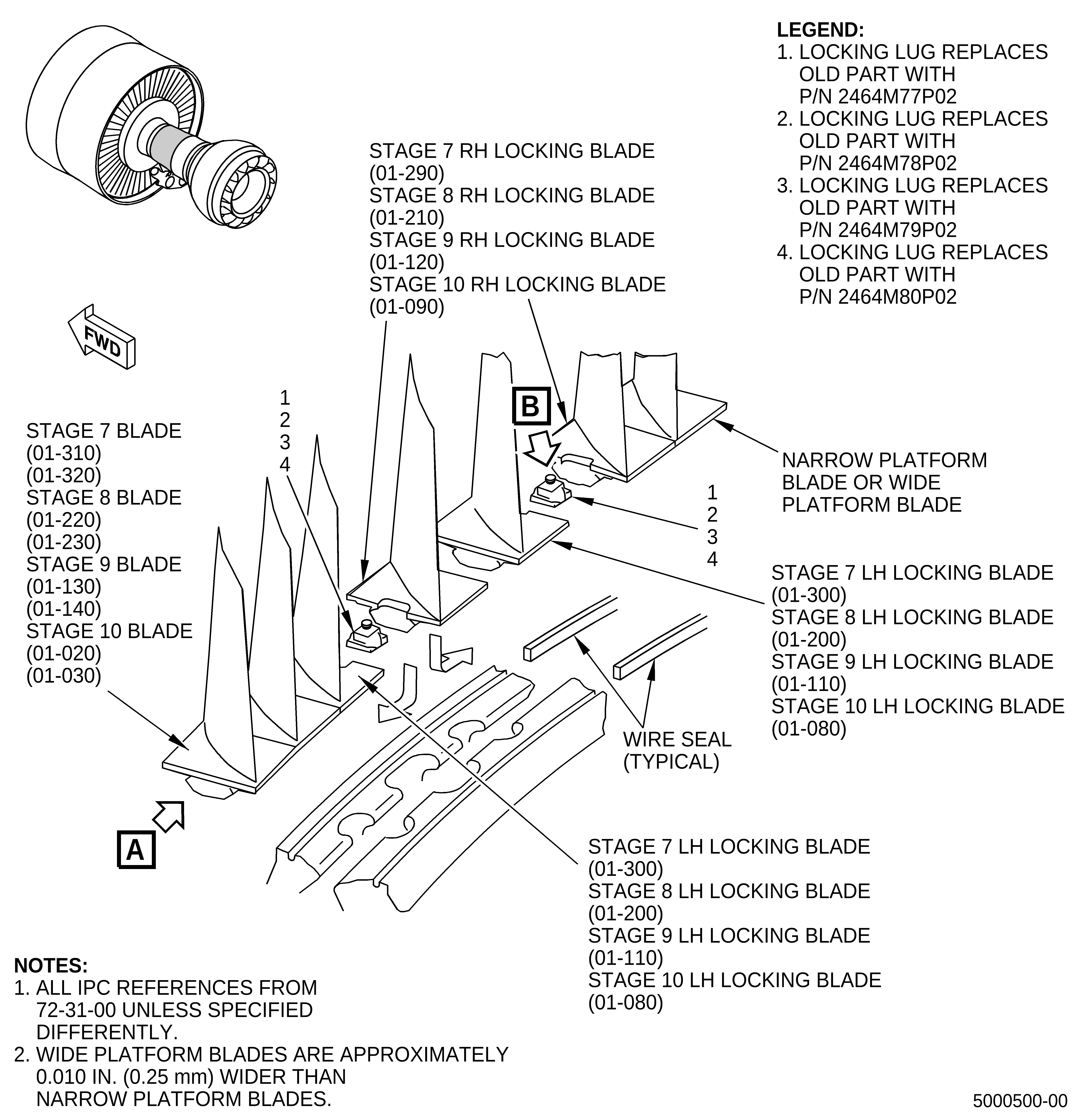
| (2) | Install the stage 7 RH locking blades (01-290, 72-31-00), stage 7 LH locking blades (01-300), stage 7 narrow platform blade (01-310), and stage 7 wide platform blade (01-320) with the new locking lugs (1, Figure 1) as follows: |
| (a) | Use a (C05-003) pen to put an N mark (narrow) on the 52 stage 7 narrow platform blades (01-310). Refer to TASK 70-16-02-350-017 (TEMPORARY MARKING). |
| (b) | Use a (C05-003) pen to put a W mark (wide) on 26 stage 7 wide platform blades (01-320). Refer to TASK 70-16-02-350-017 (TEMPORARY MARKING). |
| NOTE: |
|
| (c) | Install 52 stage 7 narrow platform blades (01-310) in the stages 6-10 compressor spool (stage 6-10 spool) (01-481) in a counterclockwise (CCW) direction. |
| (d) | Install 26 stage 7 wide platform blades (01-320) in the stage 6-10 spool (01-481) in a CCW direction. |
| (e) | Install two stage 7 RH locking blades (01-290) and two stage 7 LH locking blades (01-300) as follows: |
| 1 | Install one stage 7 RH locking blade (01-290) and one stage 7 LH locking blade (01-300) with the slot in the blade platforms adjacent to the stage 7 loading slot of the stage 6-10 spool (01-481). |
| 2 | Install one stage 7 LH locking blade (01-300) against the stage 7 RH locking blade (01-290) so the slots point at each other. |
| NOTE: |
|
| 3 | Install one stage 7 RH locking blade (01-290) against the stage 7 LH locking blade (01-300) so the slots point at each other. |
| 4 | Move the full amount of stage 7 blades CCW to make sure that the last installed stage 7 blade does not fall out. |
| 5 | Make sure that the platforms of the blades do not overlap. |
| 6 | Move the full amount of stage 7 blades clockwise (CW) to let the removal of one stage 7 RH locking blade (01-290) and the adjacent stage 7 LH locking blade (01-300). |
| 7 | Align the stage 7 RH locking blade (01-290) and stage 7 LH locking blade (01-300), one at a time, with the center mark on the stage 6-10 spool (01-481) at the loading slot. Remove the two stage 7 blades. |
| 8 | Loosen each of the locking lug setscrews. |
| 9 | Install two locking lugs (1). Move the locking lugs (1) to let the installation of the stage 7 RH locking blade (01-290) and stage 7 LH locking blade (01-300) that were previously removed. |
| 10 | Install the stage 7 RH locking blade (01-290) and stage 7 LH locking blade (01-300) again. |
| 11 | Move the installed stage 7 blades around in the stage 6-10 spool (01-481) until the locking lugs (1) align with the locking slots of the stage 6-10 spool (01-481). |
| CAUTION: |
|
| 12 | Turn each setscrew of the locking lugs (1) a minimum of two turns to make sure that there is a correct engagement of the locking lug (1) into the locking slot. |
| NOTE: |
|
| 13 | Torque each of the locking lug setscrews to 6-10 lb in. (0.7-1.1 N.m) more than the run-on torque. |
| 14 | If the run-on torque of the setscrew is not in the limit of 3.5-30 lb in. (0.40-3.4 N.m), replace the locking lug. |
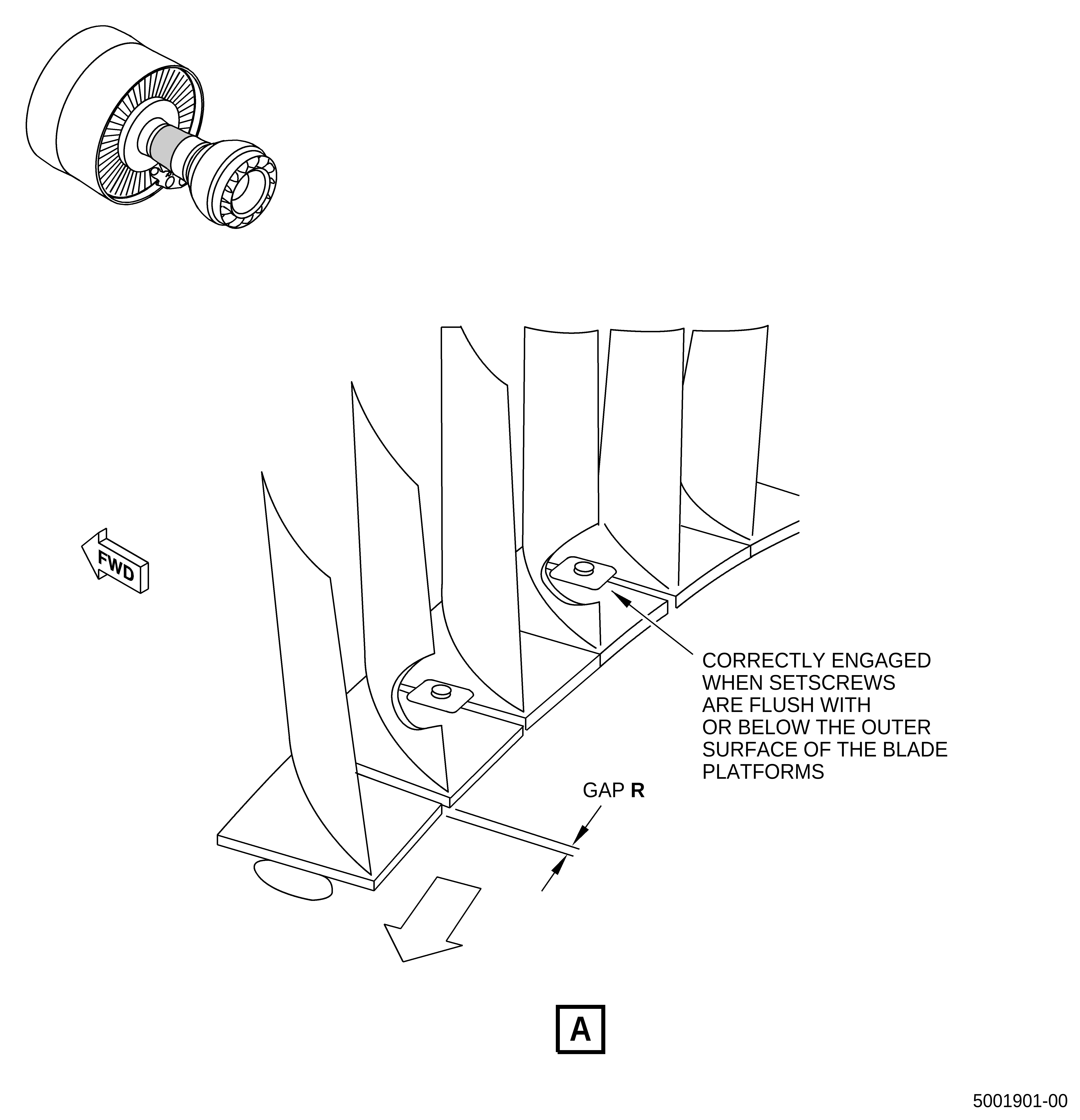
| 15 | Make sure that the setscrews are correctly engaged. The setscrews are correctly engaged if they are flush with or below the outer surface of the blade platforms. |
| (f) | Alternative Procedure Available. Slowly push all the stage 7 blades in one direction to get the maximum platform gap. Start at one side of the locking blades and push the blades around to the other side of the locking lugs. |
| (g) | Alternative Procedure. Lightly tab the stage 7 blades with a nylon drift and mallet in one direction to get the maximum platform gap. Start at one side of the locking blades and tap the blades around to the other side of the locking lugs (2). |
| (h) | Complete the installation of the stage 7 blades and new locking lugs. Refer to GEnx-1B EM, 72-31-00, ASSEMBLY 001, Subtask 72-31-00-440-132 thru Subtask 72-31-00-440-137. |
| (3) | Install the stage 8 LH locking blades (01-200), stage 8 RH locking blades (01-210), stage 8 narrow platform blades (01-220), and stage 8 wide platform blades (01-230) with the new locking lugs (2, Figure 1) as follows: |
| (a) | Use a (C05-003) pen to put an N mark (narrow) on the 49 stage 8 narrow platform blades (01-220). Refer to TASK 70-16-02-350-017 (TEMPORARY MARKING). |
| (b) | Use a (C05-003) pen to put an W mark (wide) on the 31 stage 8 wide platform blades (01-230). Refer to TASK 70-16-02-350-017 (TEMPORARY MARKING). |
| NOTE: |
|
| (c) | Install 49 stage 8 narrow platform blades (01-220) in the stage 6-10 spool (01-481) in a CCW direction. |
| (d) | Install 31 stage 8 wide platform blades (01-230) in the stage 6-10 spool (01-481) in a CCW direction. |
| (e) | Install two stage 8 LH locking blades (01-200) and two stage 8 RH locking blades (01-210) as follows: |
| 1 | Install one stage 8 RH locking blade (01-210) and one stage 8 LH locking blade (01-200) with the slot in the blade platforms adjacent to the stage 8 loading slot of the stage 6-10 spool (01-481). |
| 2 | Install one stage 8 LH locking blade (01-200) against the stage 8 RH locking blade (01-210) so the slots point at each other. |
| NOTE: |
|
| 3 | Install one stage 8 RH locking blade (01-210) against the stage 8 LH locking blade (01-200) so the slots point at each other. |
| 4 | Move the full amount of stage 8 blades CCW to make sure that the last installed stage 8 blade does not fall out. |
| 5 | Make sure that the platforms of the blades do not overlap. |
| 6 | Move the full amount of stage 8 blades CW to let the removal of one stage 8 LH locking blade (01-200) and the adjacent stage 8 RH locking blade (01-210). |
| 7 | Align the stage 8 LH locking blade (01-200) and stage 8 RH locking blade (01-210), one at a time, with the center mark on the stage 6-10 spool (01-481) at the loading slot. Remove the two stage 8 blades. |
| 8 | Loosen each of the locking lug setscrews. |
| 9 | Install two locking lugs (2). Move the locking lugs to let the installation of the stage 8 LH locking blade (01-200) and stage 8 RH locking blade (01-210) that were removed. |
| 10 | Install the stage 8 LH locking blade (01-200) and stage 8 RH locking blade (01-210) again. |
| 11 | Move the installed stage 8 blades around in the stage 6-10 spool (01-480) until the locking lugs (2) align with the locking slots of the stage 6-10 spool (01-480). |
| CAUTION: |
|
| 12 | Turn each setscrew of the locking lugs (2) a minimum of two turns to make sure that there is a correct engagement of the locking lug (2) into the locking slot. |
| NOTE: |
|
| 13 | Torque each of the locking lug setscrews to 6-10 lb in. (0.7-1.1 N.m) more than the run-on torque. |
| 14 | If the run-on torque of the setscrew is not in the limit of 3.5-30 lb in. (0.40-3.4 N.m), replace the locking lug (2). |
| 15 | Make sure that the setscrews are correctly engaged. The setscrews are correctly engaged if they are flush with or below the outer surface of the blade platforms. |
| (f) | Alternative Procedure Available. Slowly push all the stage 8 blades in one direction to get the maximum platform gap. Start at one side of the locking blades and push the blades around to the other side of the locking lugs. |
| (g) | Alternative Procedure. Lightly tab the stage 8 blades with a nylon drift and mallet in one direction to get the maximum platform gap. Start at one side of the locking blades and tap the blades around to the other side of the locking lugs (2). |
| (h) | Complete the installation of the stage 8 blades and new locking lugs. Refer to GEnx-1B EM, 72-31-00, ASSEMBLY 001, Subtask 72-31-00-440-134 thru Subtask 72-31-00-440-138. |
| (4) | Install the stage 9 LH locking blades (01-110), stage 9 RH locking blades (01-120), stage 9 narrow platform blades (01-130), and stage 9 wide platform blades (01-140) with the new locking lugs (3, Figure 1) as follows: |
| (a) | Use a (C05-003) pen to put an N mark (narrow) on the 64 stage 9 narrow platform blades (01-130). Refer to TASK 70-16-02-350-017 (TEMPORARY MARKING). |
| (b) | Use a (C05-003) pen to put a W mark (wide) on the 18 stage 9 wide platform blades (01-140). Refer to TASK 70-16-02-350-017 (TEMPORARY MARKING). |
| NOTE: |
|
| (c) | Install 64 stage 9 narrow platform blades (01-130) in the stage 6-10 spool (01-481) in a CCW ALF direction. |
| (d) | Install 18 stage 9 wide platform blades (01-140) in the stage 6-10 spool (01-481) in a CCW ALF direction. |
| (e) | Install two stage 9 LH locking blades (01-110) and two stage 9 RH locking blades (01-120) as follows: |
| 1 | Install one stage 9 RH locking blade (01-120) and one stage 9 LH locking blade (01-110) with the slots in the blade platforms adjacent to the stage 9 loading slot of the stage 6-10 spool (01-481). |
| 2 | Install one stage 9 LH locking blade (01-110) against the stage 9 RH locking blade (01-120) so the slots point at each other. |
| NOTE: |
|
| 3 | Install one stage 9 RH locking blade (01-120) against the stage 9 LH locking blade (01-110) so the slots point at each other. |
| 4 | Move the full amount of stage 9 blades CCW to make sure that the last installed stage 9 blade does not fall out. |
| 5 | Make sure that the platforms of the blades do not overlap. |
| 6 | Move the full amount of stage 9 blades CW to let the removal of one stage 9 LH locking blade (01-110) and the adjacent stage 9 RH locking blade (01-120). |
| 7 | Align the stage 9 LH locking blade (01-110) and stage 9 RH locking blade (01-120), one at a time, with the center mark on the stage 6-10 spool (01-481) at the loading slot. Remove the two stage 9 blades. |
| 8 | Loosen each of the locking lug setscrews. |
| 9 | Install two locking lugs (3). Move the locking lugs to let the installation of the stage 9 LH locking blade (01-110) and the stage 9 RH locking blade (01-120) that were previously removed. |
| 10 | Install the stage 9 LH locking blade (01-110) and stage 9 RH locking blade (01-120) again. |
| 11 | Move the installed stage 9 blades around in the stage 6-10 spool (01-481) until the locking lugs (3) align with the locking slots of the stage 6-10 spool (01-481). |
| CAUTION: |
|
| 12 | Turn each setscrew of the locking lugs a minimum of two turns to make sure that there is a correct engagement of the locking lug into the locking slot. |
| NOTE: |
|
| 13 | Torque each of the locking lug setscrews to 6-10 lb in. (0.7-1.1 N.m) more than the run-on torque. |
| 14 | If the run-on torque of the setscrew is not in the limit of 3.5-30 lb in. (0.40-3.4 N.m), replace a locking lug (3). |
| 15 | Make sure that the setscrews are correctly engaged. The setscrews are correctly engaged if they are flush with or below the outer surface of the blade platforms. |
| (f) | Alternative Procedure Available. Slowly push all the stage 9 blades in one direction to get the maximum platform gap. Start at one side of the locking blades and push the blades around to the other side of the locking lugs. |
| (g) | Alternative Procedure. Lightly tab the stage 9 blades with a nylon drift and mallet in one direction to get the maximum platform gap. Start at one side of the locking blades and tap the blades around to the other side of the locking lugs (2). |
| (h) | Complete the installation of the stage 9 blades and new locking lugs. Refer to GEnx-1B EM, 72-31-00, ASSEMBLY 001, Subtask 72-31-00-440-139 thru Subtask 72-31-00-440-140. |
| (5) | Install the stage 10 LH locking blades (01-080), stage 10 RH locking blades (01-090), stage 10 narrow platform blades (stage 10 blades) (01-020), and stage 10 wide platform blades (stage 10 blades) (01,030) with the new locking lug (4, Figure 1) as follows: |
| (a) | Use a (C05-003) pen to put an N mark (narrow) on the 63 stage 10 narrow platform blades (01-020). Refer to TASK 70-16-02-350-017 (TEMPORARY MARKING). |
| (b) | Use a (C05-003) pen to put a W mark (wide) on the 23 stage 10 wide platform blades (01-030). Refer to TASK 70-16-02-350-017 (TEMPORARY MARKING). |
| NOTE: |
|
| (c) | Install 63 stage 10 blades (01-020) in the stage 6-10 spool (01-481) in a CCW ALF direction. |
| (d) | Install 23 stage 10 blades (01-030) in the stage 6-10 spool (01-481) in a CCW ALF direction. |
| (e) | Install two stage 10 LH locking blades (01-080) and two stage 10 RH locking blades (01-090) as follows: |
| 1 | Install one stage 10 RH locking blade (01-090) and one stage 10 LH locking blade (01-080) with the slots in the blade platforms adjacent to the stage 10 loading slot of the stage 6-10 spool (01-481). |
| 2 | Install one stage 10 LH locking blade (01-080) against the stage 10 RH locking blade (01-090) so the slots point at each other. |
| NOTE: |
|
| 3 | Install one stage 10 RH locking blade (01-090) against the stage 10 LH locking blade (01-080) so the slots point at each other. |
| 4 | Move the full amount of stage 10 blades CCW to make sure that the last installed stage 10 blade does not fall out. |
| 5 | Make sure that the platforms of the blades do not overlap. |
| 6 | Move the full amount of stage 10 blades CW to let the removal of one stage 10 LH locking blade (01-080) and the adjacent stage 10 RH locking blade (01-090). |
| 7 | Align the stage 10 LH locking blade (01-080) and stage 10 RH locking blade (01-090), one at a time, with the center mark on the stage 6-10 spool (01-481) at the loading slot. Remove the two stage 10 blades. |
| 8 | Loosen each of the locking lug setscrews. |
| 9 | Install two locking lugs (4). Move the locking lugs to let the installation of the stage 10 LH locking blade (01-080) and stage 10 RH locking blade (01-090) that were removed. |
| 10 | Install the stage 10 LH locking blade (01-080) and stage 10 RH locking blade (01-090) again. |
| 11 | Move the installed stage 10 blades around in the stage 6-10 spool (01-481) until the locking lugs (4) align with the locking slots of the stage 6-10 spool (01-481). |
| CAUTION: |
|
| 12 | Turn each setscrew of the locking lugs a minimum of two turns to make sure that there is a correct engagement of the locking lug into the locking slot. |
| NOTE: |
|
| 13 | Torque each of the locking lug setscrews to 6-10 lb in. (0.7-1.1 N.m) more than the run-on torque. |
| 14 | If the run-on torque of the setscrew is not in the limit of 3.5-30 lb in. (0.40-3.4 N.m), replace the locking lug. |
| 15 | Make sure that the setscrews are correctly engaged. The setscrews are correctly engaged if they are flush with or below the outer surface of the blade platforms. |
| (f) | Alternative Procedure Available. Slowly push all the stage 10 blades in one direction to get the maximum platform gap. Start at one side of the locking blades and push the blades around to the other side of the locking lugs. |
| (g) | Alternative Procedure. Lightly tab the stage 8 blades with a nylon drift and mallet in one direction to get the maximum platform gap. Start at one side of the locking blades and tap the blades around to the other side of the locking lugs (2). |
| (h) | Complete the installation of the stage 10 blades and new locking lugs. Refer to GEnx-1B EM, 72-31-00, ASSEMBLY 001, Subtask 72-31-00-440-142 thru Subtask 72-31-00-440-143. |
| (6) | Complete the assembly and balance of the stages 6-10 spool (01-481). Refer to GEnx-1B EM, 72-31-00, ASSEMBLY 001, Subtask 72-31-00-440-144. |