| GEnx-1B SERVICE BULLETIN - 72-0248 R00 | Revised: 04/01/2015 | |
| SB 72-0248 R00 ENGINE - General (72-00-00) - TCF Accelerometer Routing Optimization | Issued: 04/01/2015 | |
| GEnx-1B SERVICE BULLETIN - 72-0248 R00 | Revised: 04/01/2015 | |
| SB 72-0248 R00 ENGINE - General (72-00-00) - TCF Accelerometer Routing Optimization | Issued: 04/01/2015 | |
| GE PROPRIETARY INFORMATION | |
| The information contained in this document is GE proprietary information and is disclosed in confidence. It is the property of GE and shall not be used, disclosed to others or reproduced without the express written consent of GE, including, but without limitation, it is not to be used in the creation, manufacture, development, or derivation of any repairs, modifications, spare parts, designs, or configuration changes or to obtain FAA or any other government or regulatory approval to do so. If consent is given for reproduction in whole or in part, this notice and the notice set forth on each page of this document shall appear in any such reproduction in whole or in part. | |
| This technical data is considered EAR controlled pursuant to 15 CFR Parts 730-774 respectively. Transfer of this data by any means to a Non-US Person, whether in the United States or abroad, without the proper U.S. Government authorization (e.g., License, exemption, NLR, etc.), is strictly prohibited. | |
| Copyright (2015) General Electric Company, U.S.A. |
| 1. | PLANNING INFORMATION |
| A. | Effectivity |
| * * * FOR GEnx-1B54, -1B54/P1, -1B54/P2, -1B58, -1B58/P1, -1B58/P2, -1B64, -1B64/P1, -1B64/P2, -1B67, -1B67/P1, -1B67/P2, -1B70, -1B70/72/P1, -1B70/72/P2, -1B70/75/P1, -1B70/75/P2, -1B70/P1, -1B70/P2, -1B74/75/P1, -1B74/75/P2, -1B75/P1, -1B75/P2, -1B78/P2 |
| This Service Bulletin has been introduced in production to these GEnx-1B engines: |
| • |
|
| These serial numbers are the best available data. |
| The support bracket P/N 2319M62G01, bracket P/N 2351M34G01, and low pressure turbine (LPT) supply air ducts (air ducts) P/N 2403M43G01 and P/N 2403M37G01 are affected by this Service Bulletin. |
| B. | Description |
| This Service Bulletin introduces new support bracket P/N 2554M80G01, bracket P/N 2554M81G01, and air duct P/N 2554M82G01. |
| C. | Compliance |
| Category 7 |
| GE recommends that you do this Service Bulletin at customer's convenience/option. |
| NOTE: |
|
| D. | Concurrent Requirements |
| None. |
| E. | Reason |
| (1) | Objective: |
| To introduce new parts, improve reliability, and improve maintainability. |
| (2) | Condition: |
| The current wiring routing includes a sharp bend in the wire between the accelerometer body and the first support bracket, as a result of this, local damage was observed. |
| (3) | Cause: |
| Initial routing design was completed in accordance with minimum radio recommendations. |
| (4) | Improvement: |
| The new proposed routing results in a larger bend radius between the accelerometer sensor and the first support. |
| (5) | Substantiation: |
| Substantiation is by analysis and comparative analysis. |
| F. | Approval |
| The data contained in this Service Bulletin has been reviewed by the appropriate governmental authority and the repair(s) and modification(s) herein comply with the applicable Aviation Regulations and are APPROVED for installation in the model(s) listed in this Service Bulletin. |
| G. | Manpower |
| No additional man-hours are required to comply with this Service Bulletin. |
| H. | Weight and Balance |
| Weight and balance are not changed. |
| I. | References (Use the latest version of these documents) |
| GEK 112851, GEnx-1B Engine Manual (EM) |
| GEK 112864, GEnx-1B Engine Illustrated Parts Catalog (EIPC) |
| NOTE: |
|
| J. | Publications Affected |
| GEK 112851, GEnx-1B Engine Manual (EM) |
| GEK 112864, GEnx-1B Engine Illustrated Parts Catalog (EIPC) |
| K. | Interchangeability |
| Two-way interchangeable. |
| L. | Software Accomplishment Summary |
| Not applicable. |
| 2. | MATERIAL INFORMATION |
| A. | Material - Price and Availability |
| (1) | Parts necessary to do this Service Bulletin: |
|
| NOTE: |
|
| (2) | Other Spare Parts: |
| None. |
| (3) | Consumables: |
| None. |
| B. | Industry Support Information |
| None. |
| C. | Configuration Chart |
|
| Operation Codes DE=Delete RE=Replace RM=Remains |
| Change Codes 2=Two-way interchangeable. 5=Qualified interchangeability. Refer to paragraph 1.K., Interchangeability. |
| Support Codes A=Old parts will no longer be supplied. B=Old parts will be supplied until all old parts are sold. |
| D. | Parts Disposition |
| Use serviceable old parts for engines that have not changed. |
| E. | Tooling - Price and Availability |
| None. |
| 3. | ACCOMPLISHMENT INSTRUCTIONS |
| A. | Removal |
| (1) | For configuration 01: |
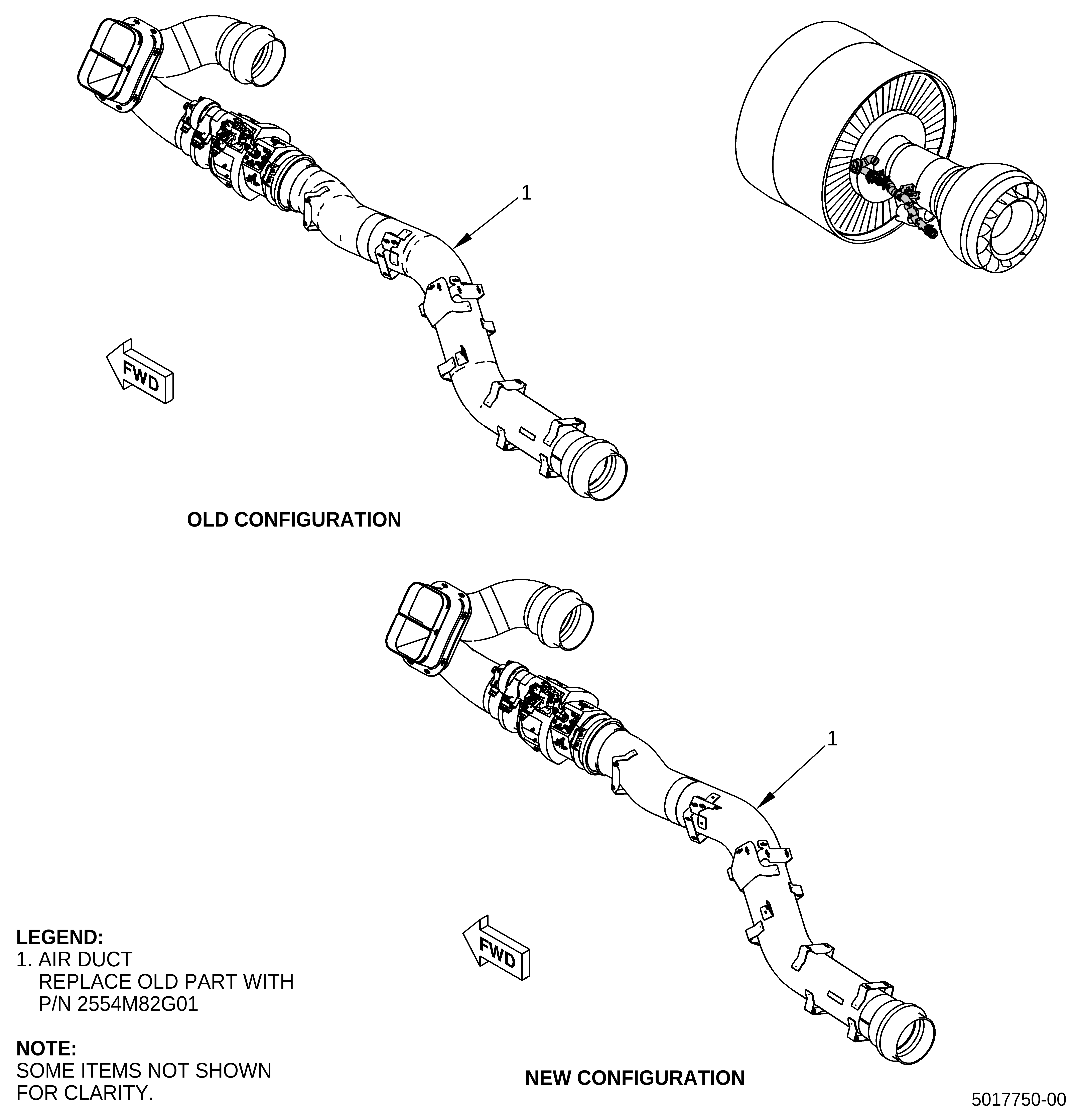
| (a) | Remove the air duct (1, Figure 1). Refer to the GEnx-1B EM, 72-00-02, DISASSEMBLY 002, CONFIG 01, Subtask 72-00-02-030-409. |
| (b) | Remove the bracket (1, Figure 2). Refer to the GEnx-1B EM, 72-54-00, DISASSEMBLY 001, CONFIG 01, Subtask 72-54-00-040-143. |
| (c) | Remove the support bracket (3, Figure 2). Refer to the GEnx-1B EM, 72-54-00, DISASSEMBLY 001, CONFIG 01, Subtask 72-54-00-040-150. |
| (2) | For configuration 02: |
| (a) | Remove the air duct (1, Figure 1). Refer to the GEnx-1B EM, 72-00-02, DISASSEMBLY 002, CONFIG 02, Subtask 72-00-02-030-584. |
| (b) | Remove the bracket (1, Figure 2). Refer to the GEnx-1B EM, 72-54-00, DISASSEMBLY 001, CONFIG 02, Subtask 72-54-00-040-173. |
| (c) | Remove the support bracket (3, Figure 2). Refer to the GEnx-1B EM, 72-54-00, DISASSEMBLY 001, CONFIG 02, Subtask 72-54-00-040-179. |
| B. | Installation |
| (1) | For configuration 01: |
| (a) | Install the new air duct (1, Figure 1). Refer to the GEnx-1B EM, 72-00-02, ASSEMBLY 005, CONFIG 01, Subtask 72-00-02-440-152. |
| (b) | Install the new bracket (1, Figure 2). Refer to the GEnx-1B EM, 72-54-00, ASSEMBLY 001, CONFIG 01, Subtask 72-54-00-440-013 and do as follows: |
| 1 | Put the new bracket (1, Figure 2) on the LH ALF vent adapter (01-210, 72-54-00). |
| 2 | Continue with the bolt installation. Refer to the GEnx-1B EM, 72-54-00, ASSEMBLY 001, CONFIG 01, Subtask 72-54-00-440-013. |
| (c) | Install the new support bracket (3, Figure 2). Refer to the GEnx-1B EM, 72-54-00, ASSEMBLY 001, CONFIG 01, Subtask 72-54-00-440-189 and do as follows: |
| 1 | Put the new support bracket (3, Figure 2) on the air adapter (01-240, 72-54-00). |
| 2 | Continue with the installation. Refer to the GEnx-1B EM, 72-54-00, ASSEMBLY 001, CONFIG 01, Subtask 72-54-00-440-189. |
| (2) | For configuration 02: |
| (a) | Install the new air duct (1, Figure 1). Refer to the GEnx-1B EM, 72-00-02, ASSEMBLY 005, CONFIG 02, Subtask 72-00-02-440-315. |
| (b) | Install the new bracket (1, Figure 2). Refer to the GEnx-1B EM, 72-54-00, ASSEMBLY 001, CONFIG 02, Subtask 72-54-00-440-306 and do as follows: |
| 1 | Put the new bracket (1, Figure 2) on the LH ALF vent adapter (01A-210, 72-54-00). |
| 2 | Continue with the bolt installation. Refer to the GEnx-1B EM, 72-54-00, ASSEMBLY 001, CONFIG 02, Subtask 72-54-00-440-306. |
| (c) | Install the new support bracket (3, Figure 2). Refer to the GEnx-1B EM, 72-54-00, ASSEMBLY 001, CONFIG 02, Subtask 72-54-00-440-317 and do as follows: |
| 1 | Put the new support bracket (3, Figure 2) on the air adapter (01A-240, 72-54-00). |
| 2 | Continue with the installation. Refer to the GEnx-1B EM, 72-54-00, ASSEMBLY 001, CONFIG 02, Subtask 72-54-00-440-317. |