| GEnx-1B SERVICE BULLETIN - 72 - 0322 R 02 | Revised: 07/02/2024 | |
| SB 72-0322 R 02 ENGINE - Fan Stator Module, Lower Bifurcation, and Related Parts (72-00-00) - Lower Bifurcation Insulation Blanket Redesign | Issued: 10/12/2016 |
| GEnx-1B SERVICE BULLETIN - 72 - 0322 R 02 | Revised: 07/02/2024 | |
| SB 72-0322 R 02 ENGINE - Fan Stator Module, Lower Bifurcation, and Related Parts (72-00-00) - Lower Bifurcation Insulation Blanket Redesign | Issued: 10/12/2016 |
| GE Designated: -CONFIDENTIAL- | |
| The information contained in this document is GE proprietary information and is disclosed in confidence. It is the property of GE and shall not be used, disclosed to others or reproduced without the express written consent of GE, including, but without limitation, it is not to be used in the creation, manufacture, development, or derivation of any repairs, modifications, spare parts, designs, or configuration changes or to obtain FAA or any other government or regulatory approval to do so. If consent is given for reproduction in whole or in part, this notice and the notice set forth on each page of this document shall appear in any such reproduction in whole or part. | |
| This technical data is considered subject to the Export Administration Regulations (EAR) pursuant to 15 CFR Parts 730-774. Transfer of this data by any means to a Non-U.S. Person, whether in the United States or abroad, without the proper U.S. Government authorization (e.g., License, exemption, NLR, etc.), is strictly prohibited. | |
| Copyright (2024 ) General Electric Company, U.S.A. |
| TRANSMITTAL INFORMATION |
| REVISION 2 TO SERVICE BULLETIN 72-0322 |
| Revision 2 is issued to update paragraphs 1., PLANNING INFORMATION, 2., MATERIAL INFORMATION, and 3., ACCOMPLISHMENT INSTRUCTIONS. |
| Revision 1 was issued July 24, 2018. The original was issued October 12, 2016. Revision bars in the left margin identify changes. |
| 1. | PLANNING INFORMATION |
| A. | Effectivity |
| * * * FOR GEnx-1B64, -1B64/P1, -1B64/P2, -1B67, -1B67/P1, -1B67/P2, -1B70, -1B70/75/P1, -1B70/75/P2, -1B70/P1, -1B70/P2, -1B70C/P1, -1B70C/P2, -1B74/75/P1, -1B74/75/P2 |
| This Service Bulletin has been introduced in production to these GEnx-1B engines: |
| • |
|
| These serial numbers are the best available data. |
| The bifurcation fire blanket P/N 2417M80P01, bifurcation fire blanket P/N 2417M81P01, blanket P/N 2402M87P01, support strap P/N 2498M04P01, support bracket P/N 2418M34G01, support bracket P/N 2588M91G01, and lower bifurcation assembly P/N 2305M80G02 are affected by this Service Bulletin. |
| B. | Description |
| This Service Bulletin introduces new bifurcation fire blanket P/N 2739M99P01, new blanket P/N 2740M42P01, and new support brackets P/N 2694M27G01, P/N 2723M75P01, and P/N 2723M76P01. |
| C. | Compliance |
| Category 7 |
| GE recommends that you do this Service Bulletin at customer's convenience. |
| Impact E |
| This recommendation is to improve the cost of ownership, reduce maintenance requirements or is a product improvement. |
| NOTE: |
|
| D. | Concurrent Requirements |
| None. |
| E. | Reason |
| (1) | Objective: |
| To introduce new parts and to improve maintainability. |
| (2) | Condition: |
| The blanket configuration has interference with the thrust reverser panels where the lower insulation blanket makes contact with the lower retainer firewall. |
| (3) | Cause: |
| The variation in the installation of the lower insulation blanket, due to the flexibility of the blanket and the variation in the harness slack distribution result in contact between the insulation blanket and the thrust reverser doors during the opening and closing cycle. |
| (4) | Improvement: |
| The excess of material on the lower insulation blanket is reduced to provide a better fit around the existing hardware. The proposed configuration reduces the folds caused by the excess of material of the lower bifurcation blanket to minimize the risk of interference with the thrust reverser cowling panels. |
| (5) | Substantiation: |
| Substantiation is by comparative analysis. |
| F. | Approval |
| The data contained in this Service Bulletin has been reviewed by the appropriate governmental authority and the repair(s) and modification(s) herein comply with the applicable Aviation Regulations and are APPROVED for installation in the model(s) listed in this Service Bulletin. |
| G. | Manpower |
| An estimate of the labor cost to accomplish this Service Bulletin may be obtained from any GEnx-1B GE Aviation authorized Service or Overhaul facility upon request. |
| H. | Weight and Balance |
| The complete compliance with this Service Bulletin increases weight by 0.55 lb (0.25 kg). |
| I. | References (Use the latest version of these documents) |
| GEnx-1B, Boeing 787 Aircraft Maintenance Manual (AMM) |
| GEK 9250, Commercial Engine Standard Practices Manual (SPM) |
| GEK 112851, GEnx-1B Engine Manual (EM) |
| GEK 112864, GEnx-1B Engine Illustrated Parts Catalog (EIPC) |
| GEnx-1B S/B 72-0223, ENGINE - Fan Stator Module, Lower Bifurcation, and Related Parts (72-00-00) - Replacement of the Support Strap with Rigid Support Bracket |
| Deleted |
| NOTE: |
|
| J. | Publications Affected |
| GEnx-1B, Boeing 787 Aircraft Maintenance Manual (AMM) |
| GEK 112851, GEnx-1B Engine Manual (EM) |
| GEK 112864, GEnx-1B Engine Illustrated Parts Catalog (EIPC) |
| K. | Interchangeability |
| Qualified interchangeability. |
| The proposed and superseded hardware should be introduced in complete engine sets. Intermixing the parts of proposed and superseded configuration on the same engine is not permitted. |
| L. | Software Accomplishment Summary |
| Not applicable. |
| 2. | MATERIAL INFORMATION |
| A. | Material - Price and Availability |
| (1) | Parts necessary to do this Service Bulletin for pre and post-GEnx-1B S/B 72-0223 configurations: |
|
| *These bolts are for pre-GEnx-1B S/B 72-0223 configuration only. |
| **Part not supplied by GE Engine Services Distribution L.L.C. Procure through local purchase. |
| NP = Not Provisioned |
| NOTE: |
|
| (2) | Other Spare Parts: |
| None. |
| (3) | Consumables: |
|
| B. | Industry Support Information |
| None. |
| C. | Configuration Chart |
|
||||||||||||||||||||||||||||||||||||||||||||||||||||||||||||||||||||||||||||||||||||||||||||||||||||||||||||||||||||||||||||||||||||||||||||||||||||||||||||||||||||||||||||||||||||||||||||||||||||||||||||||||||||||||||||||||||||||||||||||||||||||||||||||||||||||||||||||||||||||||||||||||||||||||||||||||||||||||||||||||||||||||||||||||||||||||||||||||||||||
|
||||||||||||||||||||||||||||||||||||||||||||||||||||||||||||||||||||||||||||||||||||||||||||||||||||||||||||||||||||||||||||||||||||||||||||||||||||||||||||||||||||||||||||||||||||||||||||||||||||||||||||||||||||||||||||||||||||||||||||||||||||||||||||||||||||||||||||||||||||||||||||||||||||||||||||||||||||||||||||||||||||||||||||||||||||||||||||||||||||||||||||||||||||||||||||||||||||||||||||||||||||||||||||||||||||||||||||||||||||||||||
| Operation Codes AD=Add DE=Delete RE=Replace RM=Remains |
| Change Codes 5=Qualified interchangeability. Refer to paragraph 1.K., Interchangeability. |
| Support Codes A=Old parts will no longer be supplied. C=Old parts will be supplied until December, 2021. |
| D. | Parts Disposition |
| Discard old parts. |
| E. | Tooling - Price and Availability |
| None. |
| 3. | ACCOMPLISHMENT INSTRUCTIONS |
| A. | Removal |
| (1) | For pre-GEnx-1B S/B 72-0223 configurations, disassemble as follows: |
| (a) | Remove the support strap (1, Figure 1) and support bracket (2). Refer to GEnx-1B S/B 72-0223 (latest version), paragraph 3.A. |
| (b) | Remove the firewall retainer (25-360, 72-00-00, Figure 1), the electrical block clamps (25-390 and 25-400), and the bifurcation fire blankets (5 and 6) as follows: |
| 1 | Remove the four machine bolts (7) that support the firewall retainer (25-360) in place. |
| 2 | Remove the firewall retainer (25-360) from the engine. |
| 3 | Remove the two electrical block clamps (25-390 and 25-400). |
| 4 | Remove the two bifurcation fire blankets (5 and 6). Discard the bifurcation fire blankets. |
| (c) | Remove and discard the lower insulation blanket (8). |
| (2) | For post-GEnx-1B S/B 72-0223 configurations, disassemble as follows: |
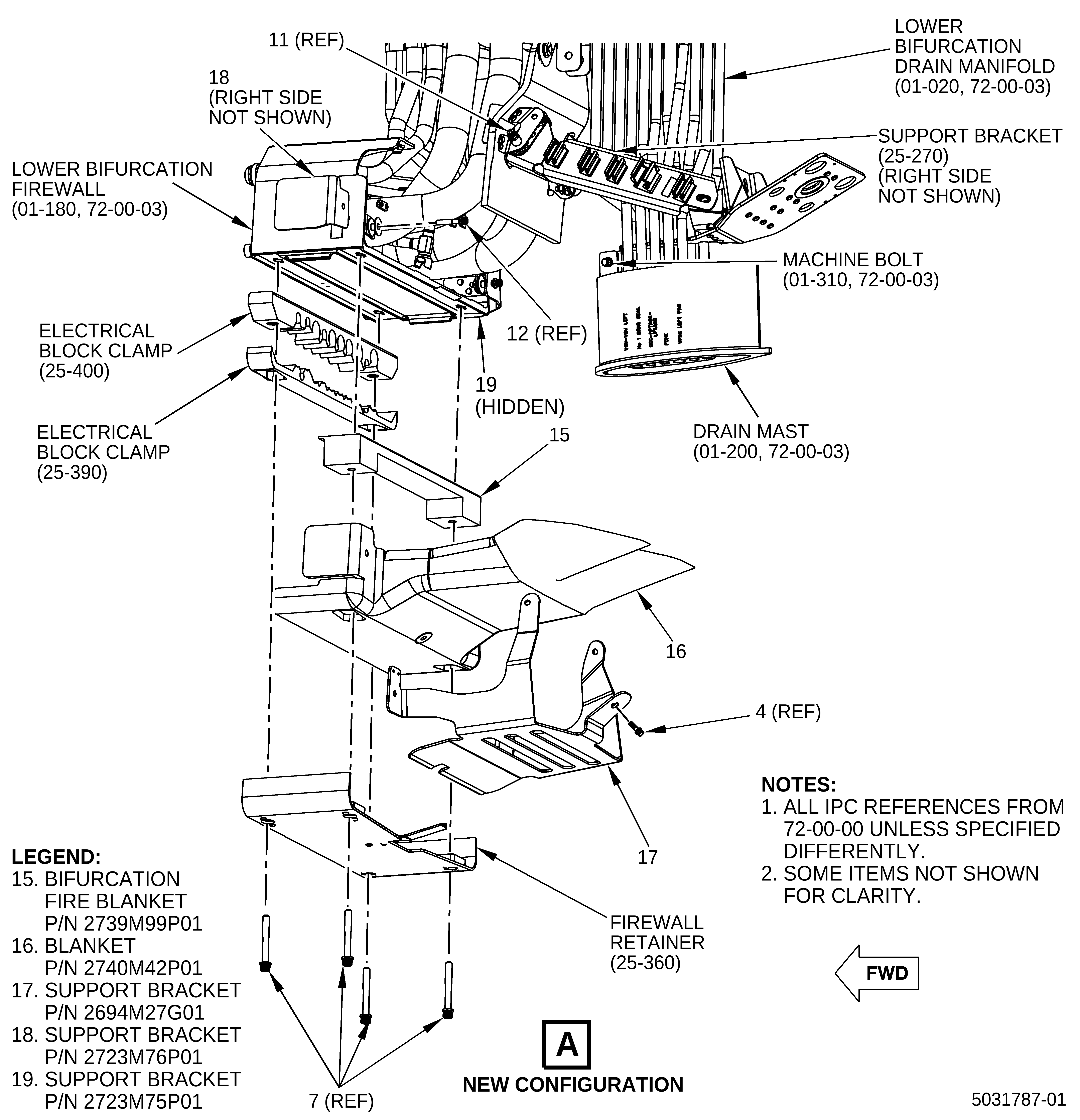
| (a) | Remove the support bracket (9, Figure 1, Sheet 2) and the blanket (10) as follows: |
| 1 | Remove the two machine bolts (11) that attach the support bracket (9) to support bracket (25-270) on the left side and to the support bracket (25-300) on the right side. |
| NOTE: |
|
| 2 | Remove the two machine bolts (12) that attach support bracket (9) and the blanket (10) to the lower bifurcation firewall (01-180, 72-00-03). |
| (b) | Remove the firewall retainer (25-360, 72-00-00), electrical block clamps (25-390 and 25-400), and the bifurcation fire blankets (13 and 14) as follows: |
| 1 | Remove the four machine bolts (7) that support the firewall retainer (25-360) in place. |
| 2 | Remove the firewall retainer (25-360). |
| 3 | Remove the electrical block clamps (25-390 and 25-400). |
| 4 | Remove the bifurcation fire blankets (13 and 14). Discard the bifurcation fire blankets. |
| B. | Installation |
| (1) | For pre-GEnx-1B S/B 72-0223 configurations, do the installation procedure as follows: |
| (a) | Install the machine bolt (01-310, 72-00-03, Figure 1, Sheet 3) that attaches the drain mast (01-200) to the lower bifurcation drain manifold (01-020). |
| (b) | Torque the machine bolt to 106-124 lb in. (11.9-14.0 Nm). |
| (c) | Install the new bifurcation fire blanket (15), the new blanket (16), and the new support bracket (17), as follows: |
| WARNING: |
|
| 1 | If necessary, use lubricant (C02-058) or engine oil (C02-023) before the installation of each machine bolt. |
| 2 | Put the new bifurcation fire blanket (15) and the new blanket (16) in position. |
| 3 | Install the machine bolt (4) and torque it to 32 to 38 lb in. (3.6 to 4.2 Nm). |
| 4 | Pull the new blanket (16) tight around the electrical harnesses and firmly attach it with safety wire (C10-071) or safety cable (C10-143). Refer to the SPM, 70-11-01, SAFETY WIRE PROCEDURE. |
| 5 | Put the new support bracket (17) on the new blanket (16), attach it with the new bracket (18) on the left side and the new bracket (19) on the right side, and install it on the lower bifurcation firewall (01-180) with two machine bolts (12). Hand-tighten the bolts. |
| 6 | Attach the new support bracket (17) to the support bracket (25-270, 72-00-00) on the left side and to the support bracket (25-300) on the right side with two machine bolts (11). Hand-tighten the bolts. |
| NOTE: |
|
| 7 | Torque the bolts (11 and 12) to 32 to 38 lb in. (3.6 to 4.2 Nm). |
| 8 | Install the firewall retainer (25-360) onto the electrical block clamps (25-400 and 25-390). |
| 9 | Put the firewall retainer (25-360) in position and install the four machine bolts (7). |
| 10 | Torque the four machine bolts (7) to 106 to 124 lb in. (11.9 to 14.0 Nm). |
| (2) | For post-GEnx-1B S/B 72-0223 configurations, do the installation procedure as follows: |
| (a) | Install the new bifurcation fire blanket (15), the new blanket (16), and the new support bracket (17), as follows: |
| WARNING: |
|
| 1 | If necessary, use lubricant (C02-058) or engine oil (C02-023) before the installation of each machine bolt. |
| 2 | Put the new bifurcation fire blanket (15) and the new blanket (16) in position. |
| 3 | Install the machine bolt (4) and torque it to 32 to 38 lb in. (3.6 to 4.2 Nm). |
| 4 | Pull the new blanket (16) tight around the electrical harnesses and firmly attach it with safety wire (C10-071) or safety cable (C10-143). Refer to the SPM, 70-11-01, SAFETY WIRE PROCEDURE. |
| 5 | Put the new support bracket (17) on the new blanket (16), attach it with the new bracket (18) on the left side and the new bracket (19) on the right side, and install it on the lower bifurcation firewall (01-180, 72-00-03) with two machine bolts (12). Hand-tighten the bolts. |
| 6 | Attach the new support bracket (17) to the support bracket (25-270, 72-00-00) on the left side and to the support bracket (25-300) on the right side with two machine bolts (11). Hand-tighten the bolts. |
| NOTE: |
|
| 7 | Torque the bolts (11 and 12) to 32 to 38 lb in. (3.6 to 4.2 Nm). |
| 8 | Install the firewall retainer (25-360) onto the electrical block clamps (25-400 and 25-390). |
| 9 | Put the firewall retainer (25-360) in position and install the four machine bolts (7). |
| 10 | Torque the four machine bolts (7) to 106 to 124 lb in. (11.9 to 14.0 Nm). |