| GEnx-1B SERVICE BULLETIN - 72-0357 R02 | Revised: 05/30/2019 | |
| SB 72-0357 R02 ENGINE - Mid Fan Shaft Assembly (72-58-00) - Introduction of New A/O Vent Center Tube P/N 2331M21G03 | Issued: 02/17/2017 | |
| GEnx-1B SERVICE BULLETIN - 72-0357 R02 | Revised: 05/30/2019 | |
| SB 72-0357 R02 ENGINE - Mid Fan Shaft Assembly (72-58-00) - Introduction of New A/O Vent Center Tube P/N 2331M21G03 | Issued: 02/17/2017 | |
| GE Designated: -CONFIDENTIAL- | |
| The information contained in this document is GE proprietary information and is disclosed in confidence. It is the property of GE and shall not be used, disclosed to others or reproduced without the express written consent of GE, including, but without limitation, it is not to be used in the creation, manufacture, development, or derivation of any repairs, modifications, spare parts, designs, or configuration changes or to obtain FAA or any other government or regulatory approval to do so. If consent is given for reproduction in whole or in part, this notice and the notice set forth on each page of this document shall appear in any such reproduction in whole or part. | |
| This technical data is considered subject to the Export Administration Regulations (EAR) pursuant to 15 CFR Parts 730-774. Transfer of this data by any means to a Non-U.S. Person, whether in the United States or abroad, without the proper U.S. Government authorization (e.g., License, exemption, NLR, etc.), is strictly prohibited. | |
| Copyright (2019) General Electric Company, U.S.A. |
| TRANSMITTAL INFORMATION |
| REVISION 2 TO SERVICE BULLETIN 72-0357 |
| Revision 2 is issued to update paragraphs 1., PLANNING INFORMATION, 2., MATERIAL INFORMATION, and 3., ACCOMPLISHMENT INSTRUCTIONS. |
| Revision 1 was issued March 06, 2018. The original was issued February 17, 2017. Revision bars in the left margin identify changes. |
| 1. | PLANNING INFORMATION |
| A. | Effectivity |
| * * * FOR GEnx-1B64, -1B64/P1, -1B64/P2, -1B67, -1B67/P1, -1B67/P2, -1B70, -1B70/75/P1, -1B70/75/P2, -1B70/P1, -1B70/P2, -1B70C/P1, -1B70C/P2, -1B74/75/P1, -1B74/75/P2, -1B76/P2, -1B76A/P2 |
| This Service Bulletin has been introduced in production to these GEnx-1B engines: |
| • |
|
| These serial numbers are the best available data. |
| The A/O vent center tube (center vent tube) P/N 2331M21G02 is affected by this Service Bulletin. |
| B. | Description |
| This Service Bulletin releases a new center vent tube P/N 2331M21G03. |
| C. | Compliance |
| Category 7 |
| GE recommends that you do this Service Bulletin at customer's option. |
| Impact E |
| This recommendation is to improve the cost of ownership, reduce maintenance requirements or is a product improvement. |
| NOTE: |
|
| D. | Concurrent Requirements |
| None. |
| E. | Reason |
| (1) | Objective: |
| To introduce a new part and improve maintainability. |
| (2) | Condition: |
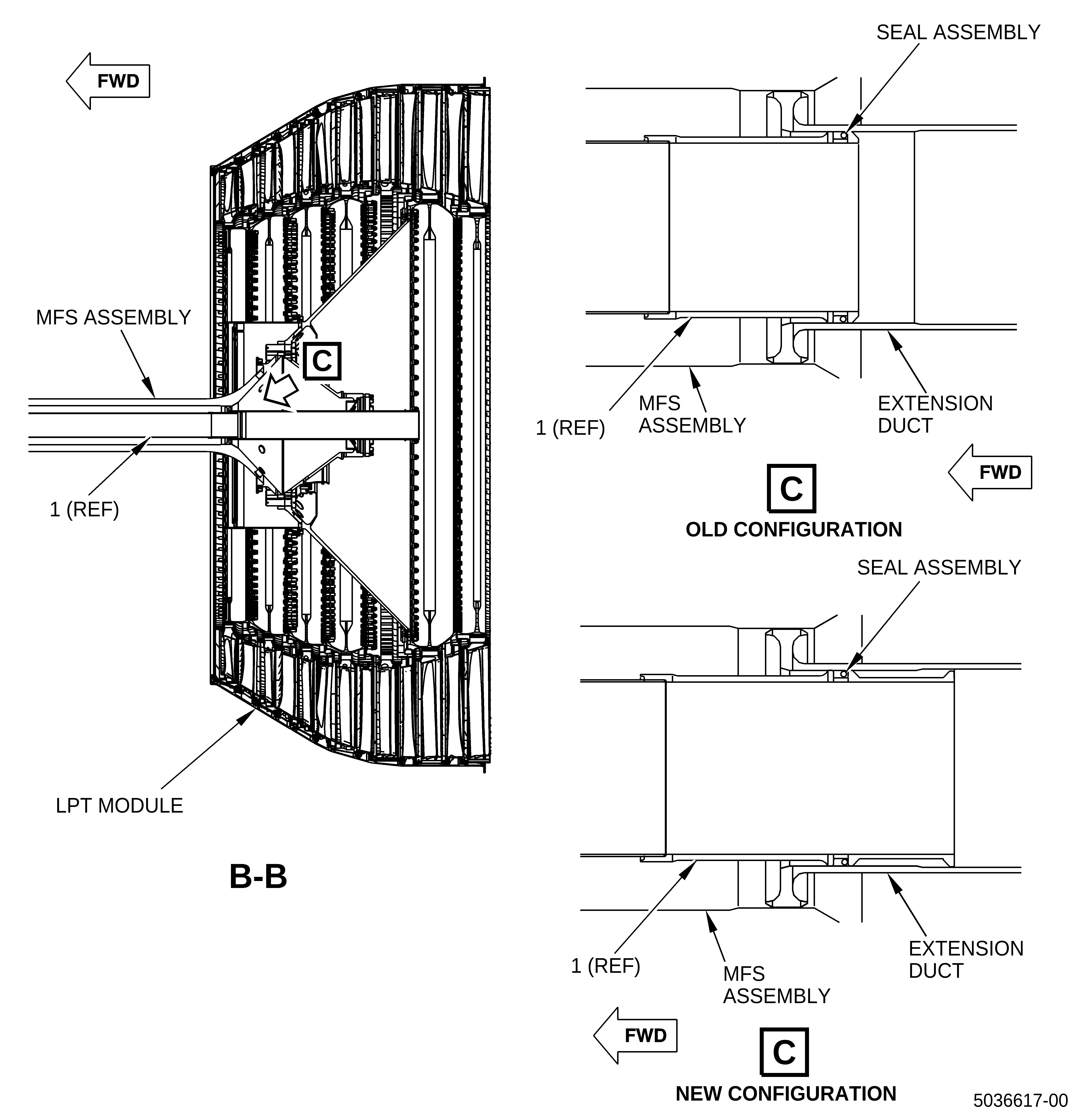
| Routine teardowns at overhaul shop found tannic oil collected in the mid fan shaft (MFS) with deteriorating paint, seals, coke, and corrosion pittings of the MFS as current center vent tube does not overlap the extension duct over a step of the extension duct. Hence oil can stand just after the seal assembly. This condition contributes the oil leak into the MFS inner. |
| (3) | Cause: |
| The oil leak into MFS inner cavity is caused by delta pressure between the MFS inner cavity depressurized in high altitude and the center vent tube across seal assembly. |
| (4) | Improvement: |
| The new center vent tube extends backward by 1.38 inch (35.052 mm), which ensures that the new center vent tube can overlap the extension duct over the step so the oil leak into the MFS inner will be prevented because waterfall condition is ensured and the oil does not stand just after the seal assembly. |
| (5) | Substantiation: |
| Substantiation is by comparative analysis. |
| F. | Approval |
| The data contained in this Service Bulletin has been reviewed by the FAA or authorized entity representing the FAA and the repair(s) and modification(s) herein comply with the applicable Aviation Regulations and are APPROVED for installation in the model(s) listed in this Service Bulletin. |
| G. | Manpower |
| No additional man-hours are required to comply with this Service Bulletin. |
| H. | Weight and Balance |
| The complete compliance with this Service Bulletin increases weight by 0.250 lb (0.113 kg). |
| I. | References (Use the latest version of this document) |
| GEK 112851, GEnx-1B Engine Manual (EM) |
| GEK 112864, GEnx-1B Engine Illustrated Parts Catalog (EIPC) |
| NOTE: |
|
| J. | Publications Affected |
| GEK 112851, GEnx-1B Engine Manual (EM) |
| GEK 112864, GEnx-1B Engine Illustrated Parts Catalog (EIPC) |
| K. | Interchangeability |
| One-way interchangeable. |
| L. | Software Accomplishment Summary |
| Not applicable. |
| 2. | MATERIAL INFORMATION |
| A. | Material - Price and Availability |
| (1) | Parts necessary to do this Service Bulletin: |
|
| NOTE: |
|
| (2) | Other Spare Parts: |
| None. |
| (3) | Consumables: |
| None. |
| B. | Industry Support Information |
| None. |
| C. | Configuration Chart |
|
||||||||||||||||||||||||||||||||||||||||||||||||||||||||||||||||||||||||||||||||||||||||||||||||||||||||||||||||||||||||||||||||||||||||||||||||||||||||||||||||||||||||||||||||||||||||||||||||||||||||||||||||||||||||||||||||||||||||||||
| Operation Codes RE=Replace RM=Remains |
| Change Codes 1=One-way interchangeable. |
| Support Codes B=Old parts will be supplied until all old parts are sold. |
| D. | Parts Disposition |
| None. |
| E. | Tooling - Price and Availability |
| None. |
| 3. | ACCOMPLISHMENT INSTRUCTIONS |
| A. | General |
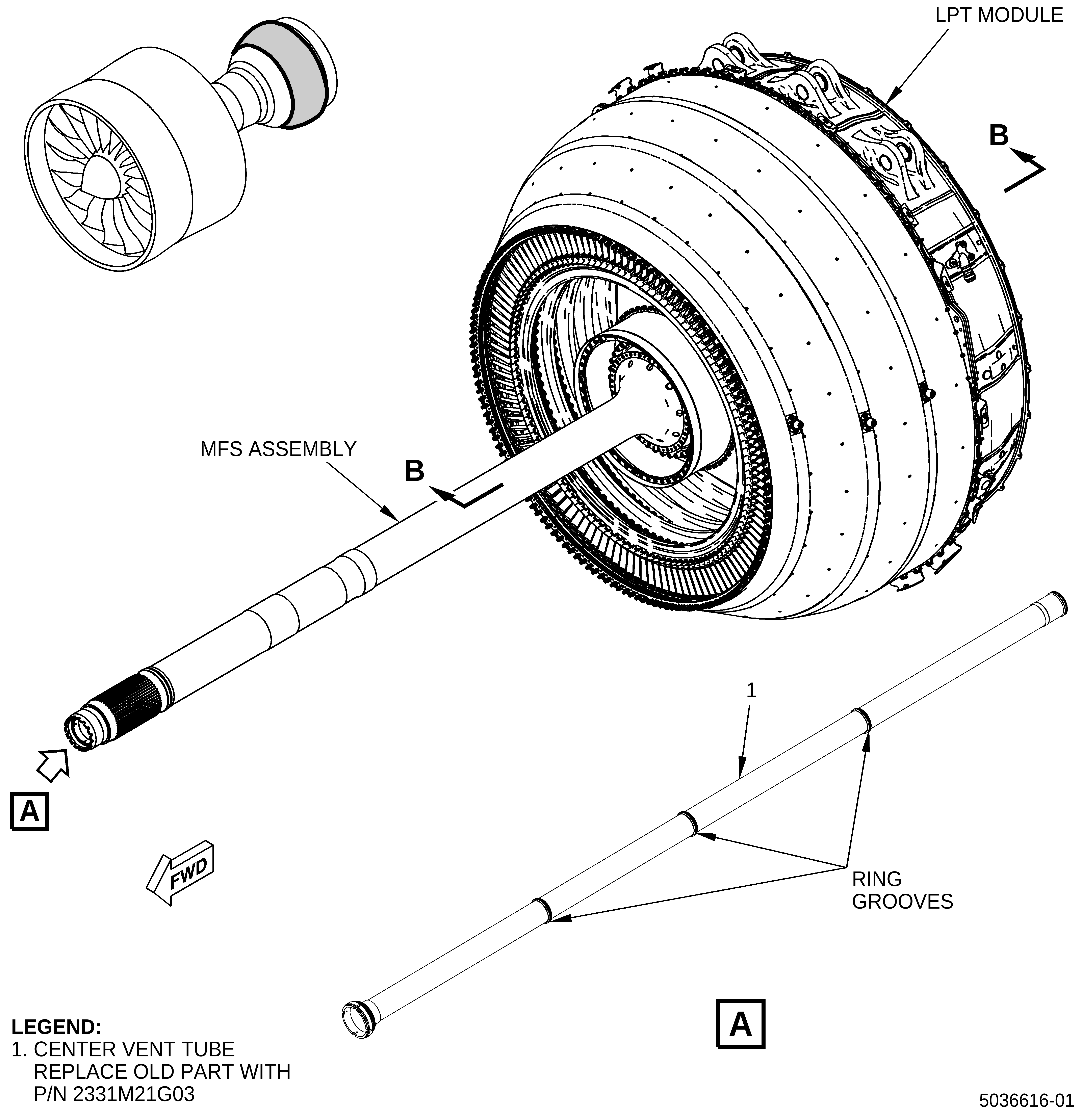
| (1) | Remove the MFS assembly (Figure 1) from the engine as follows: |
| (a) | Remove the low pressure turbine (LPT) module with the MFS assembly. Refer to the GEnx-1B EM, 72-00-04, REMOVAL 001. |
| (b) | Remove the MFS assembly (Figure 1) from the LPT module. Refer to the GEnx-1B EM, 72-00-04, DISASSEMBLY 001. |
| (2) | Disassemble the MFS assembly (Figure 1). Refer to the GEnx-1B EM, 72-58-00, DISASSEMBLY 001, CONFIGURATION 01 or CONFIGURATION 02 and do as follows: |
| (a) | Remove the center vent tube (Figure 1) from the MFS assembly. Refer to the GEnx-1B EM, 72-58-00, DISASSEMBLY 001, CONFIGURATION 01 or CONFIGURATION 02. |
| (b) | Deleted. |
| (3) | Assemble the MFS assembly with the new center vent tube P/N 2331M21G03. Refer to the GEnx-1B EM, 72-58-00, ASSEMBLY 001, CONFIGURATION 01 or CONFIGURATION 02. |
| NOTE: |
|
| (a) | Deleted. |
| (4) | Attach the MFS assembly to the LPT module. Refer to the GEnx-1B EM, 72-00-04, ASSEMBLY 001, CONFIGURATION 01 or CONFIGURATION 02. |
| (5) | Install the LPT module (Figure 1) with the MFS assembly into the propulsor. Refer to the GEnx-1B EM, 72-00-04, INSTALLATION 001. |