![]() | GEnx-1B SERVICE BULLETIN - 73-0019 R00 | Revised: 05/31/2013 |
SB 73-0019 R00 ENGINE FUEL AND CONTROL - Fuel Manifold and Tubes to TBV, LPT and HPT ACC Valves, and CCC Valve (73-11-40) - Core Compartment Cooling Tube Product Improvement | Issued: 05/31/2013 | |
GE PROPRIETARY INFORMATION | |
The information contained in this document is GE proprietary information and is disclosed in confidence. It is the property of GE and shall not be used, disclosed to others or reproduced without the express written consent of GE, including, but without limitation, it is not to be used in the creation, manufacture, development, or derivation of any repairs, modifications, spare parts, designs, or configuration changes or to obtain FAA or any other government or regulatory approval to do so. If consent is given for reproduction in whole or in part, this notice and the notice set forth on each page of this document shall appear in any such reproduction in whole or in part. | |
This technical data is considered EAR controlled pursuant to 15 CFR Parts 730-774 respectively. Transfer of this data by any means to a Non-US Person, whether in the United States or abroad, without the proper U.S. Government authorization (e.g., License, exemption, NLR, etc.), is strictly prohibited. | |
Copyright (2013) General Electric Company, U.S.A. |
1. | PLANNING INFORMATION |
A. | Effectivity |
|
This Service Bulletin has been introduced in production to these GEnx-1B engines: |
• |
|
These serial numbers are the best available data. |
The PHS tubehose P/N 2422M64P01, CCC valve head end tubehose P/N 2366M10P01, and oil supply tube P/N 2317M69P01 are affected by this Service Bulletin. |
B. | Description |
This Service Bulletin provides an installation procedure and releases new tubes to replace tube hoses and thus reduces weight. |
C. | Compliance |
Category 7 |
GE recommends that you do this Service Bulletin at customer's convenience or option. |
NOTE: |
|
D. | Concurrent Requirements |
None. |
E. | Reason |
(1) | Objective: |
To introduce new parts and to reduce weight. |
(2) | Condition: |
The current tube hose configuration on the core compartment cooling (CCC) actuation lines and accessory gear box (AGB) main fuel heat exchanger lines has no immediate negative impact on the engine, apart from adding an extra weight of 1.98 lbs (0.90 kg) which can be removed if hoses are changed to tubes. |
(3) | Cause: |
Tube hoses were added for maintainability at early stages of the engine development. |
(4) | Improvement: |
The proposed hard tube designs result in a total weight reduction of 1.98 lbs (0.90 kg) per engine. |
(5) | Substantiation: |
Substantiation is by analysis and comparative analysis. |
F. | Approval |
This Service Bulletin has been reviewed by the FAA and the repair(s) and modification(s) herein comply with the applicable Federal Aviation Regulations and are FAA APPROVED for installation in the model(s) listed in this Service Bulletin. |
G. | Manpower |
After you get access to the propulsor assembly module, you will need approximately 1 man-hour per engine to do the replacement portion of this Service Bulletin. |
H. | Weight and Balance |
The complete compliance with this Service Bulletin decreases weight by 1.98 lb (0.90 kg). |
I. | References (Use the latest version of these documents) |
GEK 9250, Commercial Engine Standard Practices Manual (SPM) |
GEK 112851, GEnx-1B Engine Manual (EM) |
GEK 112862, GEnx-1B Cleaning, Inspection, and Repair Manual (CIR) |
GEK 112863, GEnx-1B System Description Section (SDS) |
GEK 112864, GEnx-1B Engine Illustrated Parts Catalog (EIPC) |
GEK 112866, GEnx-1B Illustrated Tool and Equipment Manual (ITEM) |
NOTE: |
|
J. | Publications Affected |
GEK 112851, GEnx-1B Engine Manual (EM) |
GEK 112862, GEnx-1B Cleaning, Inspection, and Repair Manual (CIR) |
GEK 112864, GEnx-1B Engine Illustrated Parts Catalog (EIPC) |
K. | Interchangeability |
(1) | AGB heat exchanger line: |
The oil supply tube P/N 2317M69P01 is replaced with the oil supply tube P/N 2519M35G01 and is two way interchangeable. |
(2) | CCC valve actuation head and rod lines have been introduced as qualified interchangeable: |
The PHS tubehose P/N 2422M64P01 is replaced with two tubes: fuel core compartment cooling rod tube (fuel tube) P/N 2519M38G01 and fuel core compartment cooling rod manifold (fuel manifold) P/N 2519M41G01. |
The CCC valve head end tubehose P/N 2366M10P01 is replaced with two tubes: fuel core compartment cooling valve tube (fuel tube) P/N 2519M36G01 and fuel core compartment cooling valve tube (fuel tube) P/N 2519M40G01. |
The preformed packing P/N J222P013 (SIN 34751) increase in quantity from 3 to 4 and preformed packing J222P013 (SIN 38C51) increase in quantity from 1 to 2. These changes must be done as a complete set on a given engine. |
L. | Software Accomplishment Summary |
Not applicable. |
2. | MATERIAL INFORMATION |
A. | Material - Price and Availability |
(1) | Parts necessary to do this Service Bulletin: |
|
NOTE: |
|
(2) | Other Spare Parts: |
|
NOTE: |
|
(3) | Consumables: |
|
B. | Industry Support Information |
None. |
C. | Configuration Chart |
|
Operation Codes AD=Add RE=Replace RM=Remains QTC=Quantity Change |
Change Codes 2=Two-way interchangeable. 5=Qualified interchangeability. Refer to paragraph 1.K., Interchangeability. |
Support Code B=Old parts will be supplied until all old parts are sold. |
D. | Parts Disposition |
Use serviceable old parts for engines that have not changed. |
E. | Tooling - Price and Availability |
None. |
3. | ACCOMPLISHMENT INSTRUCTIONS |
A. | Disassembly |
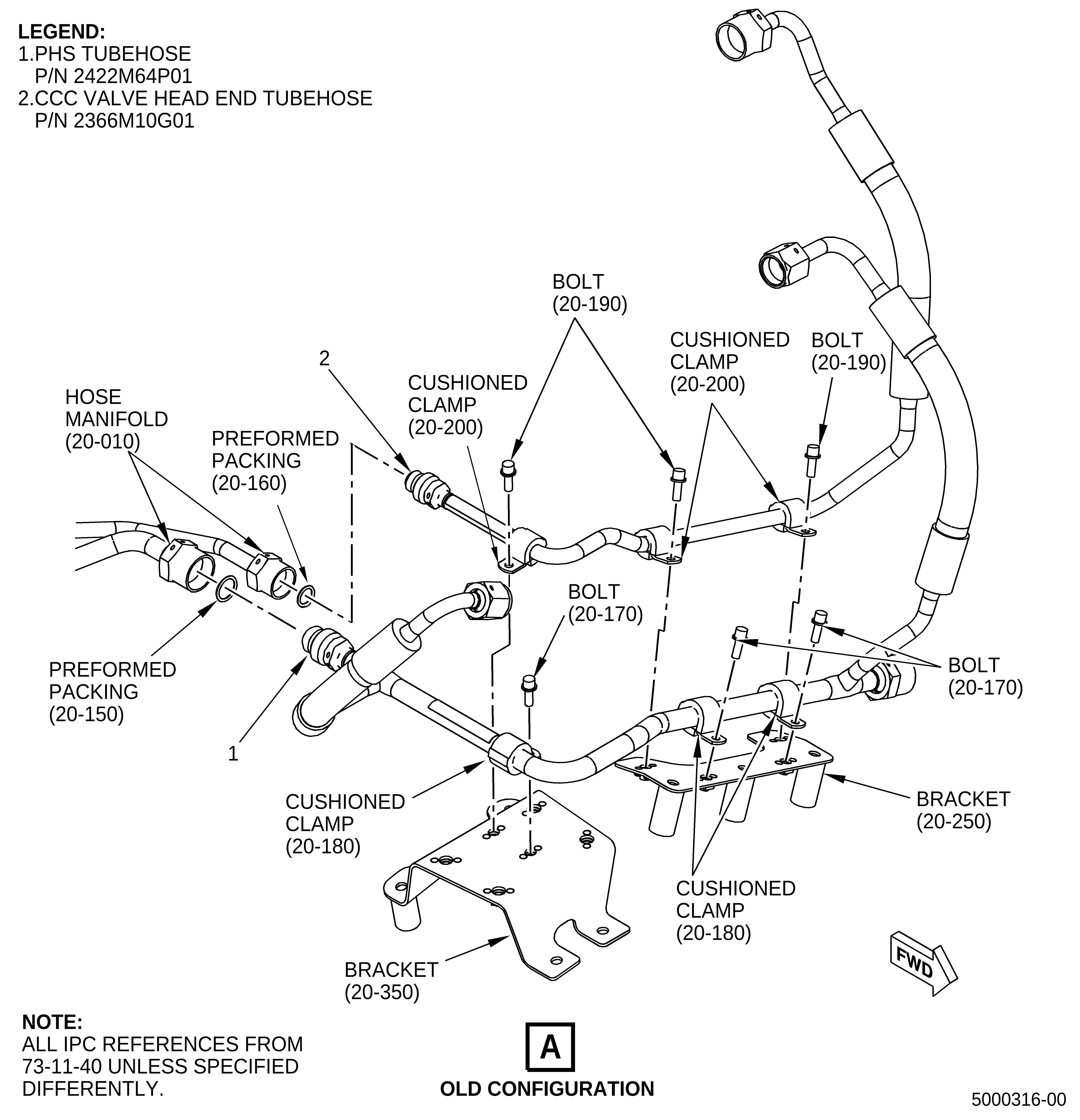
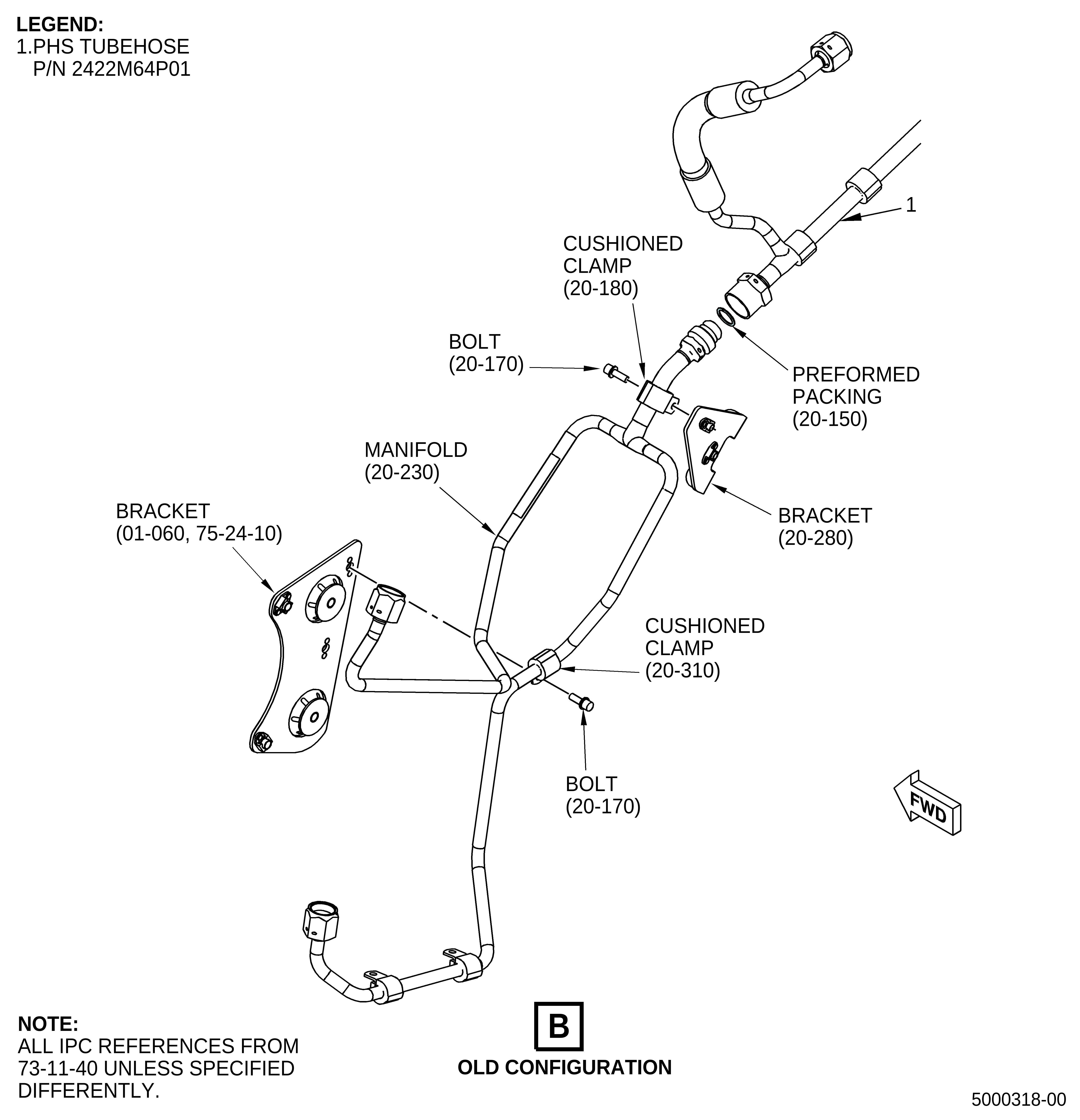
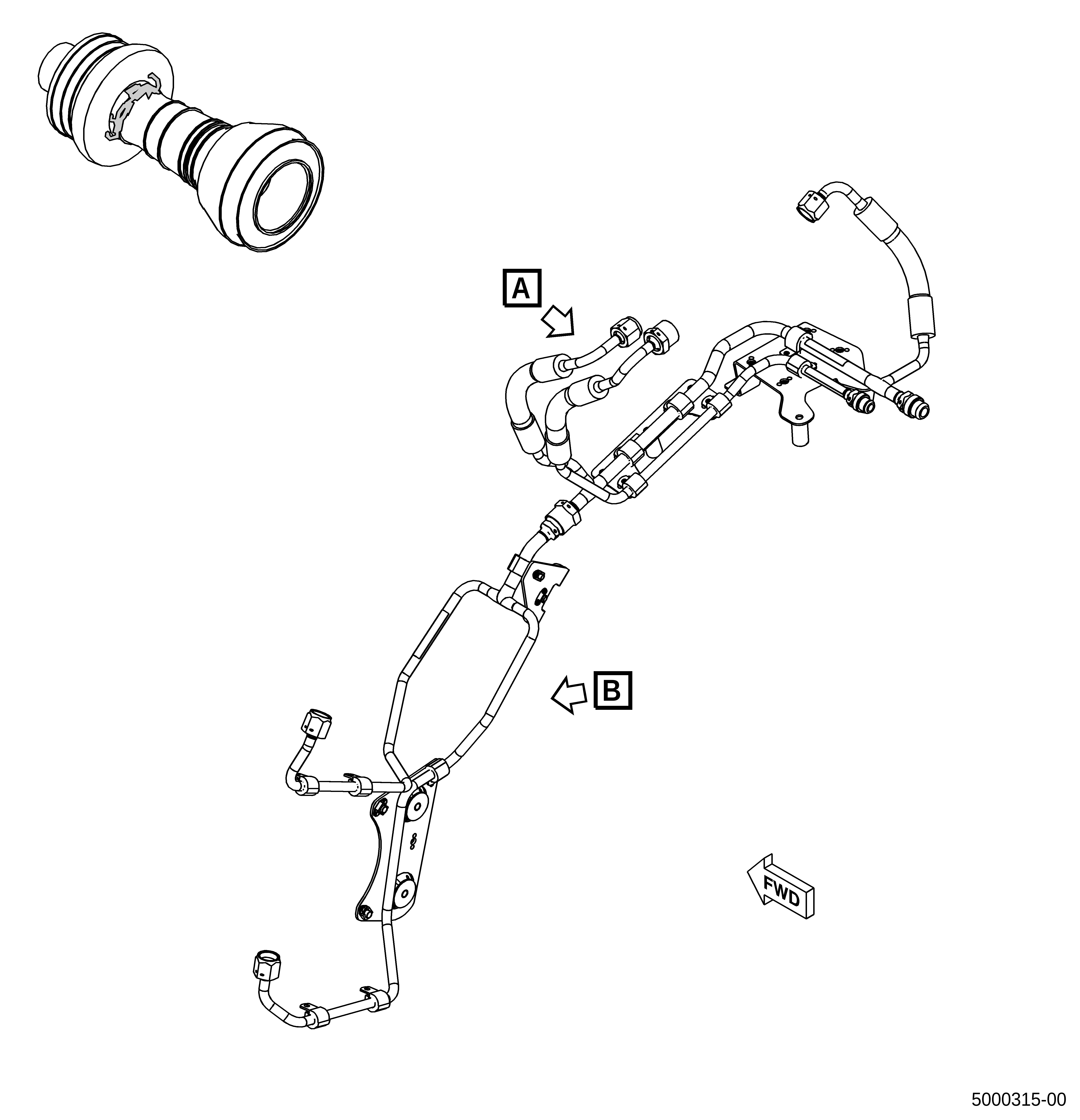
(1) | Remove the PHS tubehose (1, Figure 1, Sheet 2) and the CCC valve head end tubehose (2). Refer to the GEnx-1B EM, 72-00-02, DISASSEMBLY 003, Subtask 72-00-02-030-391. |
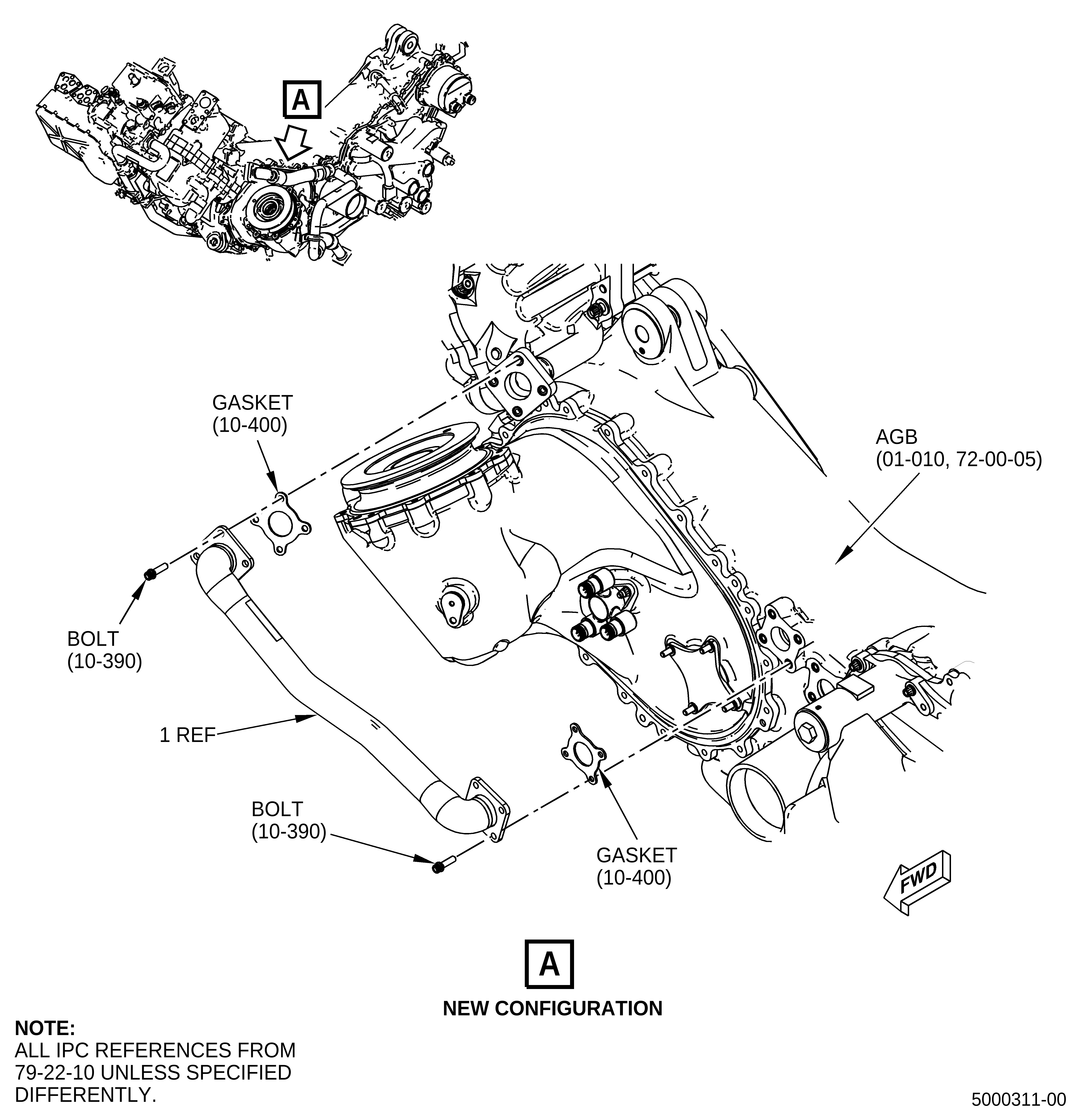
(2) | Remove the oil supply tube/hose (1, Figure 2, Sheet 1). Refer to the GEnx-1B EM 72-00-05, DISASSEMBLY 001, Subtask 72-00-05-030-028. |
B. | Assembly |
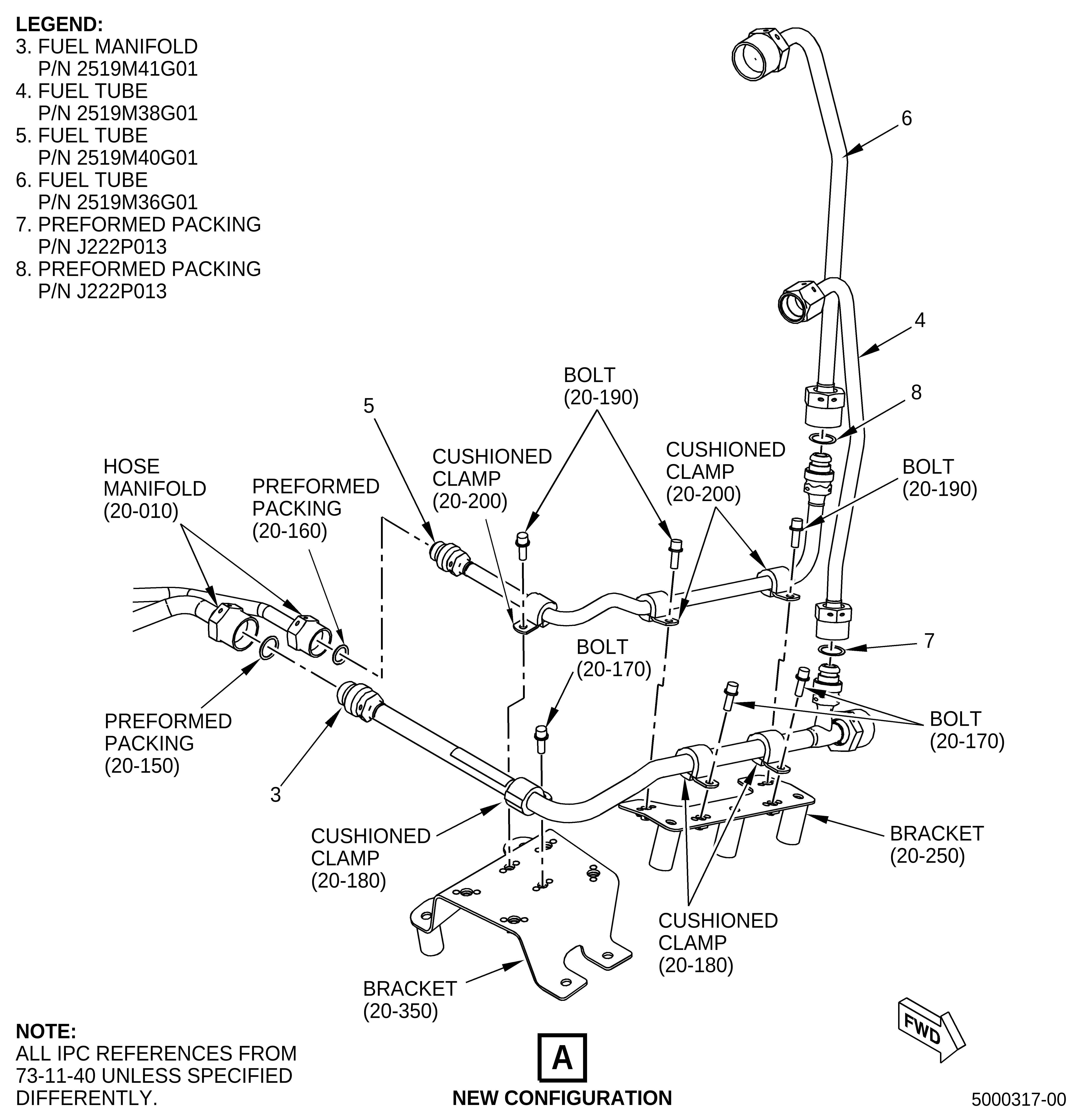
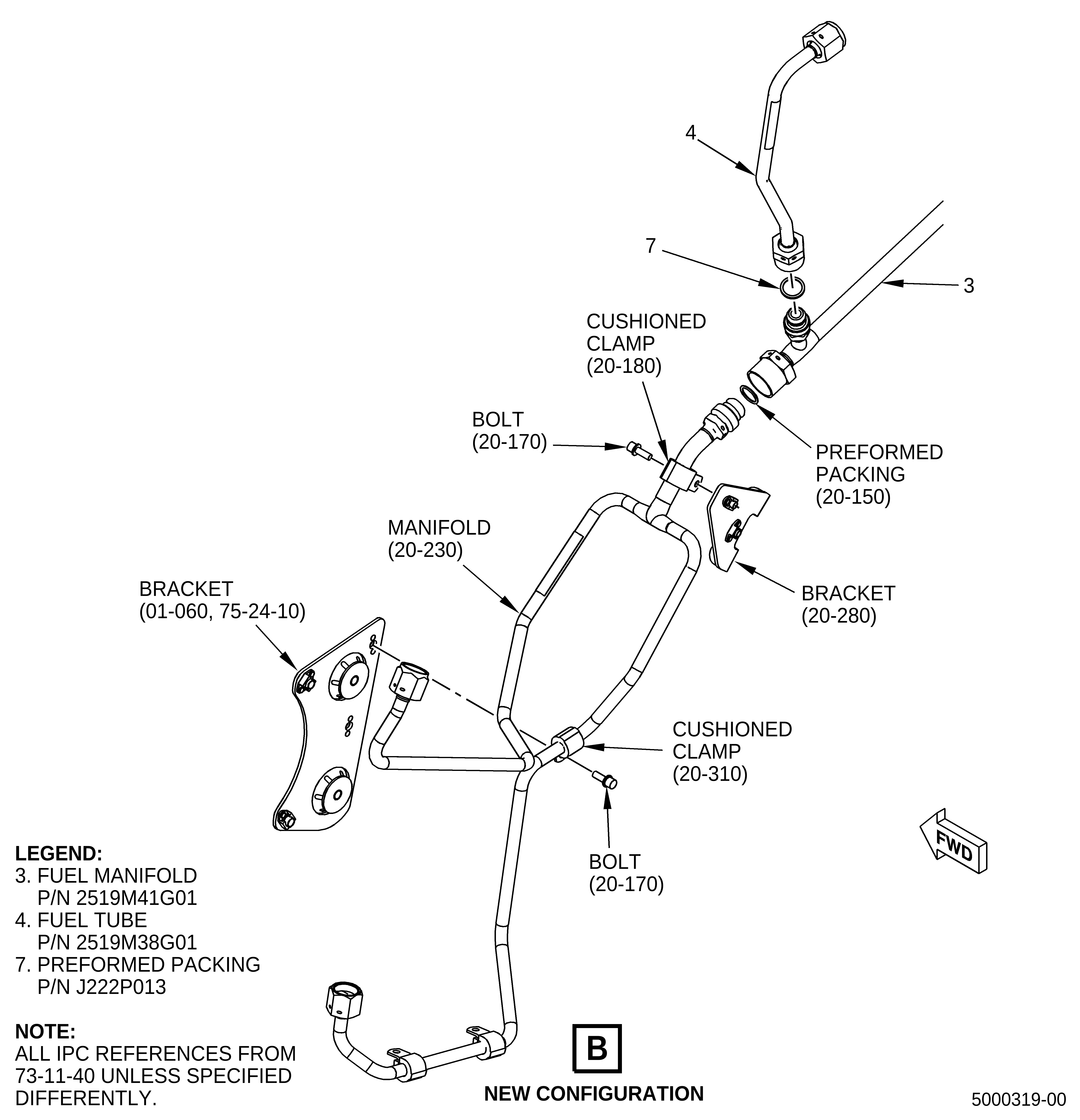
(1) | Install the fuel manifold (3, Figure 1, Sheet 3), fuel tube (4), fuel tube (5), and fuel tube (6) as follows: |
WARNING: |
|
(a) | Apply C02-019 engine oil or C02-023 engine oil to the preformed packings (20-150, 73-11-40) and preformed packings (20-210). |
(b) | Install a preformed packing (20-150) on the fuel manifold (3). |
(c) | Install a preformed packing (20-150) on the manifold (20-230). |
(d) | Connect the fuel manifold (3) to the hose manifold (20-010). |
(e) | Attach the fuel manifold (3) to the bracket (20-250) with cushioned loop clamps (cushioned clamp) (20-180) and bolts (20-170). |
(f) | Attach the fuel manifold (3) to the bracket (20-350) with a cushioned clamp (20-180) and a bolt (20-170). |
(g) | Connect the manifold (20-230) to the fuel manifold (3). |
(h) | Attach the manifold (20-230) to the bracket (20-280) with a cushioned clamp (20-180) and a bolt (20-170). |
(i) | Attach the manifold (20-230) to the bracket (01-060, 75-24-10) with a cushioned clamp (20-310, 73-11-40) and a bolt (20-170). |
(j) | Attach the fuel manifold (20-230) to the tabs on the tube (30-080) and the tabs on the tube (25-050) with cushioned clamps (20-310) and bolts (20-300). |
(k) | Install a preformed packing (7) on the fuel tube (3). |
(l) | Connect the fuel manifold (3) to the fuel tube (4). |
(m) | Torque the B-nut on the hose manifold (20-010) as follows: |
1 | Torque the B-nut to 55-65 lb ft (75-88 N.m). |
2 | Loosen the B-nut and then torque again to 55-65 lb ft (75-88 N.m). |
3 | Apply a final torque of 55-65 lb ft (75-88 N.m) to the B-nut. |
(n) | Torque the B-nut on the fuel tube (4) as follows: |
1 | Torque the B-nut to 55-65 lb ft (75-88 N.m). |
2 | Loosen the B-nut and then torque again to 55-65 lb ft (75-88 N.m). |
3 | Apply a final torque of 55-65 lb ft (75-88 N.m) to the B-nut. |
(o) | Torque the B-nut on the fuel manifold (3) as follows: |
1 | Torque the B-nut to 55-65 lb ft (75-88 N.m). |
2 | Loosen the B-nut and then torque again to 55-65 lb ft (75-88 N.m). |
3 | Apply a final torque of 55-65 lb ft (75-88 N.m) to the B-nut. |
(p) | Safety the B-nut on the hose manifold (20-010), fuel manifold (3) and fuel tube (4) with C10-071 safety wire or C10-143 safety cable. |
(q) | Torque the bolts (20-170) to 32-38 lb in. (3.6-4.3 N.m). |
(r) | Torque the bolts (20-300) to 32-38 lb in. (3.6-4.3 N.m). |
WARNING: |
|
(s) | Apply C02-019 engine oil or C02-023 engine oil to preformed packings (20-160). |
(t) | Install preformed packings (8) on the fuel tube (5). |
(u) | Connect the fuel tube (5) to the hose manifold (20-010). |
(v) | Attach the fuel tube (5) to the bracket (20-250) with cushioned loop clamps (cushioned clamp) (20-200) and bolts (20-190). |
(w) | Connect the fuel tube (5) to the fuel tube (6). |
(x) | Torque the B-nut on the hose manifold (20-010) as follows: |
1 | Torque the B-nut to 460-540 lb in. (52.0-61.0 N.m). |
2 | Loosen the B-nut until the B-nut is loose and then apply torque again to 460-540 lb in. (52.0-61.0 N.m). |
3 | Apply a final torque of 460-540 lb in. (52.0-61.0 N.m) to the B-nut. |
(y) | Torque the B-nut on the fuel tube (6) as follows: |
1 | Torque the B-nut to 55-65 lb ft (75-88 N.m). |
2 | Loosen the B-nut and then torque again to 55-65 lb ft (75-88 N.m). |
3 | Apply a final torque of 55-65 lb ft (75-88 N.m) to the B-nut. |
(z) | Safety the B-nut on the hose manifold (20-010) and fuel tube (6) with C10-071 safety wire or C10-143 safety cable. |
(aa) | Torque the bolts (20-190) to 32-38 lb in. (3.6-4.3 N.m). |
(2) | Install the oil supply tube/hose (1, Figure 2). Refer to GEnx-1B EM, 72-00-05, ASSEMBLY 001, Subtask 72-00-05-430-022. |