| GEnx-1B SERVICE BULLETIN - 73-0040 R01 | Revised: 09/04/2015 | |
| SB 73-0040 R01 ENGINE FUEL AND CONTROL - General (73-00-00) - Introduction of New W30 Harness, W31 Harness, and Support Brackets | Issued: 11/26/2014 | |
| GEnx-1B SERVICE BULLETIN - 73-0040 R01 | Revised: 09/04/2015 | |
| SB 73-0040 R01 ENGINE FUEL AND CONTROL - General (73-00-00) - Introduction of New W30 Harness, W31 Harness, and Support Brackets | Issued: 11/26/2014 | |
| GE PROPRIETARY INFORMATION | |
| The information contained in this document is GE proprietary information and is disclosed in confidence. It is the property of GE and shall not be used, disclosed to others or reproduced without the express written consent of GE, including, but without limitation, it is not to be used in the creation, manufacture, development, or derivation of any repairs, modifications, spare parts, designs, or configuration changes or to obtain FAA or any other government or regulatory approval to do so. If consent is given for reproduction in whole or in part, this notice and the notice set forth on each page of this document shall appear in any such reproduction in whole or in part. | |
| This technical data is considered EAR controlled pursuant to 15 CFR Parts 730-774 respectively. Transfer of this data by any means to a Non-US Person, whether in the United States or abroad, without the proper U.S. Government authorization (e.g., License, exemption, NLR, etc.), is strictly prohibited. | |
| Copyright (2015) General Electric Company, U.S.A. |
| TRANSMITTAL INFORMATION |
| REVISION 1 TO SERVICE BULLETIN 73-0040 |
| Revision 1 is issued to update paragraph 2., MATERIAL INFORMATION. |
| The original was issued November 26, 2014. Revision bars in the left margin identify changes. |
| 1. | PLANNING INFORMATION |
| A. | Effectivity |
| * * * FOR GEnx-1B64, -1B64/P1, -1B64/P2, -1B67, -1B67/P1, -1B67/P2, -1B70, -1B70/75/P1, -1B70/75/P2, -1B70/P1, -1B70/P2, -1B74/75/P2 |
| This Service Bulletin is applicable to all GEnx-1B engines. |
| This Service Bulletin has been introduced in production to these GEnx-1B engines: |
| • |
|
| These serial numbers are the best available data. |
| The W30 harness VIN 504643-9 and W31 harness VIN 504644-7 and their associated support brackets are affected by this Service Bulletin. |
| B. | Description |
| This Service Bulletin introduces improved W30 and W31 harnesses with their associated mounting brackets and attaching hardware. |
| C. | Compliance |
| Category 4 |
| GE recommends that you do this Service Bulletin when the W30 and/or W31 harness is/are exposed. |
| NOTE: |
|
| This Service Bulletin is offered to improve the reliability or performance of your GE product, or to help prevent the occurrence of the event or condition described in this Service Bulletin. If the operator elects not to participate in the bulletin, that decision will be taken into consideration by GE in evaluating future product performance issues that may arise in the operators fleet. |
| D. | Concurrent Requirements |
| None. |
| E. | Reason |
| (1) | Objective: |
| To introduce redesigned brackets and harnesses for the fire detector sensing elements of the GEnx-1B engine and to improve product reliability. |
| (2) | Condition: |
| The current design of the W30 and W31 harnesses have shown distress during revenue service that was due to vibration, wear, and assembly/shipping damage which then has lead to the replacement of the harnesses. |
| (3) | Cause: |
| The harness distress has been attributed to multiple causes including: detector terminal positioning, harness pigtail positioning, as well as harness pigtail breakout locations, and unsupported length. |
| (4) | Improvement: |
| The new design of the harnesses and brackets addresses the causes of distress and improves the reliability of the W30 and W31 harnesses. |
| (5) | Substantiation: |
| Substantiation is by analysis and comparative analysis. |
| F. | Approval |
| The data contained in this Service Bulletin has been reviewed by the appropriate governmental authority and the repair(s) and modification(s) herein comply with the applicable Aviation Regulations and are APPROVED for installation in the model(s) listed in this Service Bulletin. |
| G. | Manpower |
| After you get access to the W30 and W31 harnesses, you will need approximately 8.0 man-hours for each engine. |
| H. | Weight and Balance |
| The complete compliance with this Service Bulletin increases weight by 1.50 lb (0.68 kg). |
| I. | References (Use the latest version of these documents) |
| GEK 112851, GEnx-1B Engine Manual (EM) |
| GEK 112864, GEnx-1B Engine Illustrated Parts Catalog (EIPC) |
| GEK 114019, GEnx-1B Component Maintenance Manual (CMM) |
| GEnx-1B Boeing 787 Aircraft Maintenance Manual (AMM) |
| NOTE: |
|
| J. | Publications Affected |
| GEK 112851, GEnx-1B Engine Manual (EM) |
| GEK 112864, GEnx-1B Engine Illustrated Parts Catalog (EIPC) |
| GEK 114019, GEnx-1B Component Maintenance Manual (CMM) |
| GEnx-1B Boeing 787 Aircraft Maintenance Manual (AMM) |
| K. | Interchangeability |
| The introduction of the product improvement must be done as a set to meet functional requirements. Mixing of the proposed and superseded hardware is not permitted. |
| L. | Software Accomplishment Summary |
| Not applicable. |
| 2. | MATERIAL INFORMATION |
| A. | Material - Price and Availability |
| (1) | Parts necessary to do this Service Bulletin: |
|
| *Part not supplied by GE Engine Services Distribution L.L.C. Procure through: |
| Unison Industries L.L.C. Elano Division 2455 Dayton-Xenia Rd. Dayton, OH 45434-7199 U.S.A. |
| **Part not supplied by GE Engine Services Distribution L.L.C. Procure through local purchase. |
| NP = Not Provisioned |
| NOTE: |
|
| (2) | Other Spare Parts: |
| None. |
| (3) | Consumables: |
|
| B. | Industry Support Information |
| GE-Unison is pleased to extend special discounted pricing for the kit P/N GENX1BHARNESS1. The kit consists of two harnesses, one W30 harness and one W31 harness, and nine attaching brackets. Please contact Unison or Unisons authorized distributor for quote and details on discounted pricing and delivery. This pricing program will expire 24 months after the original release date of this Service Bulletin. |
| Unison regional sales director contact information: Website: http://www.unisonindustries.com/contact/sales.html |
| Authorized aviation distribution contact information: E-mail: unisondistribution@aarcorp.com Phone: +1 630-227-2874 |
| C. | Configuration Chart |
|
| Operation Codes AD=Add QTC=Quantity Change RE=Replace RM=Remains |
| Change Code 5=Qualified interchangeability. Refer to paragraph 1.K., Interchangeability. |
| Support Codes A=Old parts will no longer be supplied. C=Old parts will be supplied until May, 2016. E=Old parts will be supplied, and can be used at other engine locations. |
| D. | Parts Disposition |
| Use serviceable old parts for engines that have not changed. |
| E. | Tooling - Price and Availability |
| None. |
| 3. | ACCOMPLISHMENT INSTRUCTIONS |
| A. | Removal |
| (1) | Remove the W30 harness (01-010, 73-21-66) (SIN 68800) and W31 harness (05-010) (SIN 68801) as follows: |
| (a) | For on-wing procedure. Refer to the GEnx-1B Boeing 787 AMM, DMC-B787-A-26-11-03-00A-520A-A. |
| (b) | For in-shop procedure. Refer to the GEnx-1B EM, 72-00-02, DISASSEMBLY 001, Subtask 72-00-02-030-354. |
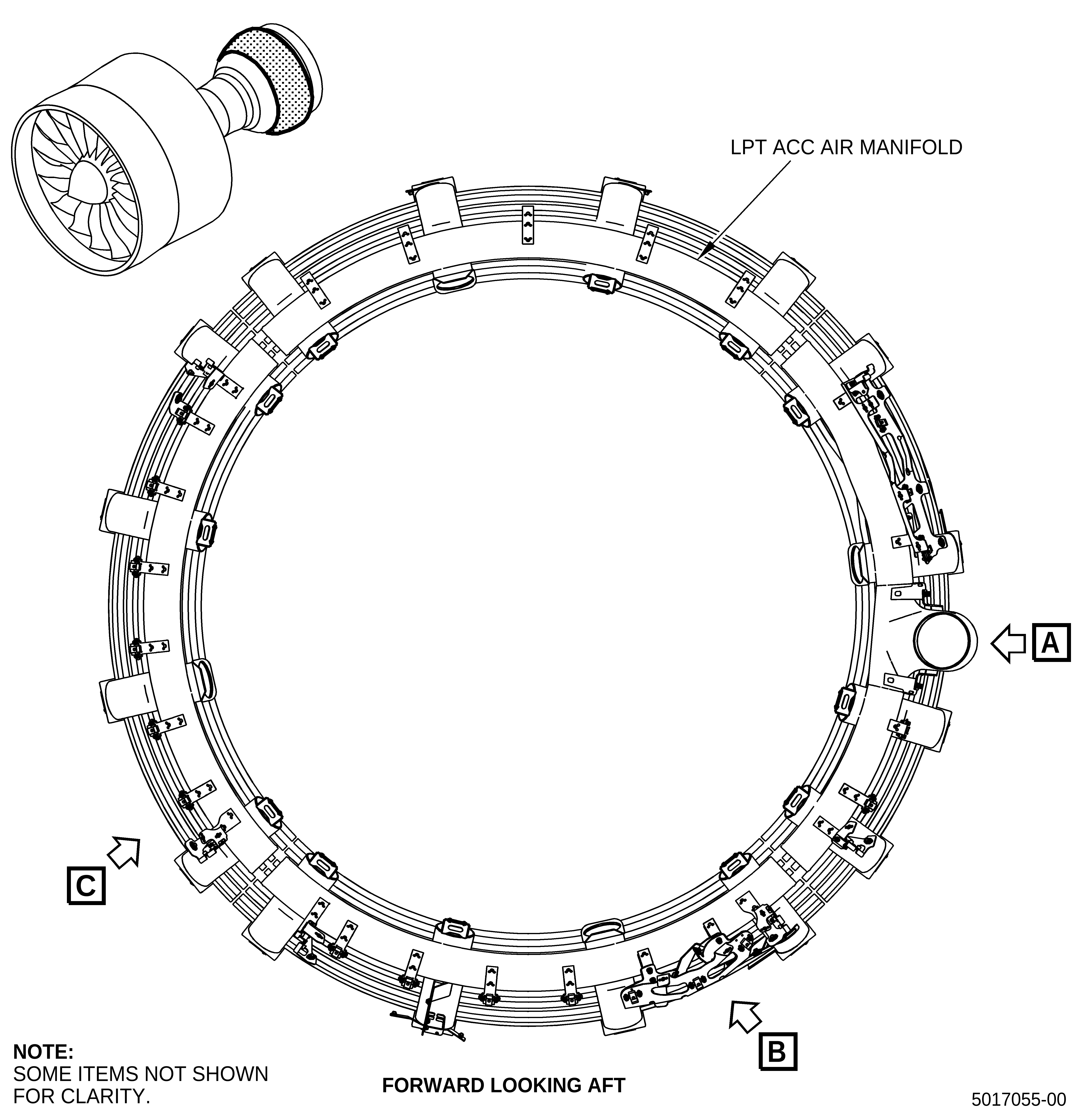
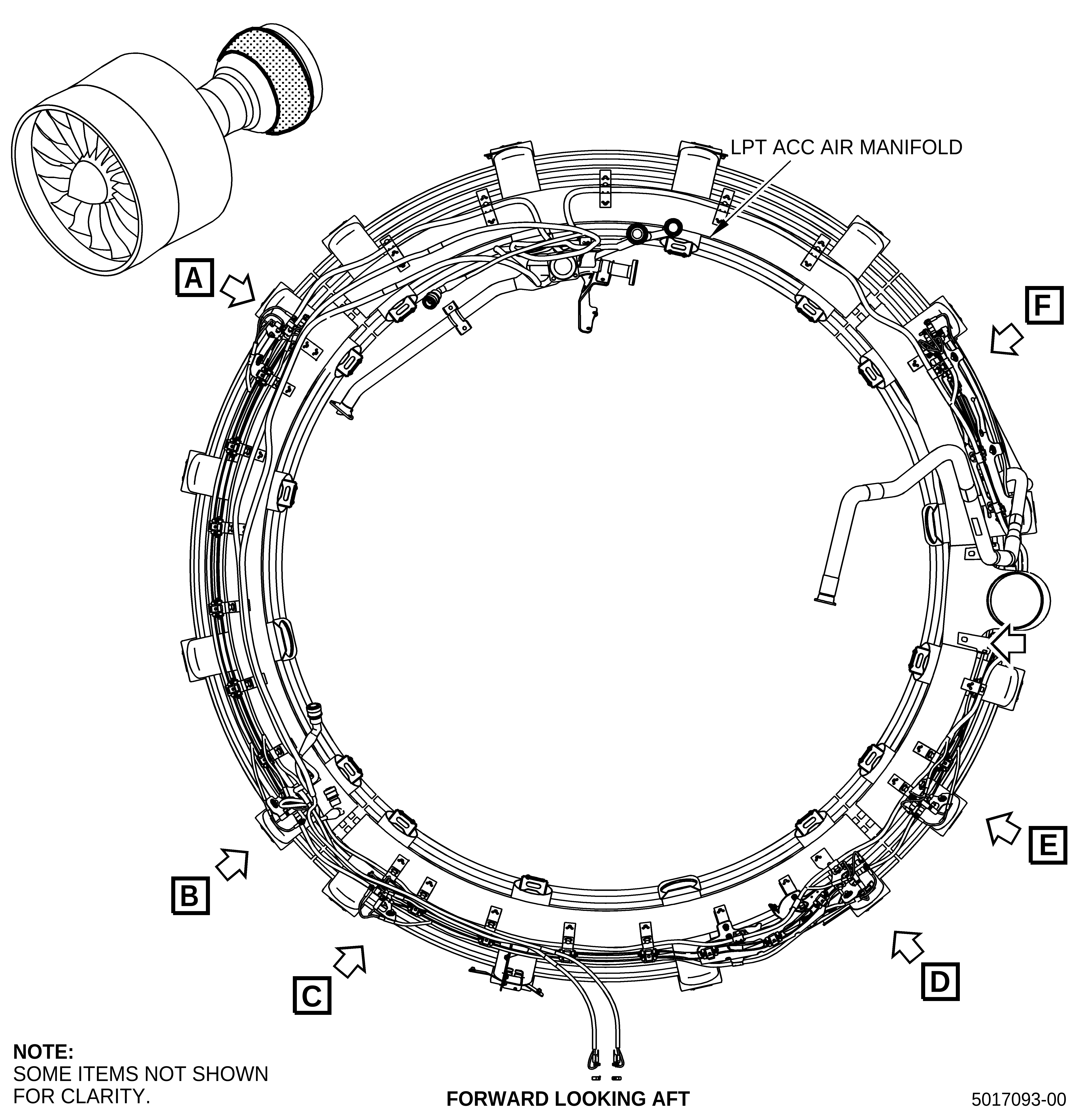
| (2) | Remove the six sensing elements (05-011, 71-00-02) (SIN C00A7), (05-061) (SIN C00A7), and (05-111) (SIN C00A7) from the low pressure turbine (LPT) active clearance control (ACC) air manifold as follows: |
| (a) | For on-wing procedure. Refer to the GEnx-1B Boeing 787 AMM, DMC-B787- A-26-11-01-01B-520A-A, Steps C.(1) thru C.(3). |
| (b) | For in-shop procedure. Refer to the GEnx-1B EM, 72-00-02, DISASSEMBLY 002 CONFIG 01 or CONFIG 02. |
| (3) | Remove the support brackets from the LPT ACC air manifold as follows: |
| (a) | Remove the double hexagon head machine bolts (bolts) (15-010, 75-24-10) (SIN 98020) that attach the end lug bracket (15-020) (SIN 9801G) to the harness support bracket (15-170) (SIN 9801D) at the 10:00 o'clock position. |
| (b) | Remove the machine bolts (bolts) (15-150) (SIN 98021) that attach the harness support bracket (15-170) (SIN 9801D) at the 9:30 o'clock position. |
| (c) | Remove the bolts (15-010) (SIN 98020) that attach the end lug bracket (15-030) (SIN 9801K) at the 7:30 o'clock position. |
| (d) | Remove the bolts (15-010) (SIN 98020) that attach the end lug bracket (15-040) (SIN 9801J) at the 7:00 o'clock position. |
| (e) | Remove the bolts (15-150) (SIN 98021) that attach the drain support bracket (15-180) (SIN 9801F) or (15-181) (SIN 9801F) at the 6:30 o'clock position. |
| NOTE: |
|
| (f) | Remove the bolts (15-010) (SIN 98020) that attach the end lug bracket (15-020) (SIN 9801G) at the 5:00 o'clock position. |
| (g) | Remove the bolts (15-010) (SIN 98020) that attach the end lug bracket (15-040) (SIN 9801J) at the 5:30 o'clock position. |
| (h) | Remove the bolts (15-010) (SIN 98020) that attach the end lug bracket (15-020) (SIN 9801G) at the 2:00 o'clock position. |
| (i) | Keep the bolts for the installation of the new brackets. |
| B. | Installation |
| (1) | Install the new support brackets and clamps for the new W30 and W31 harnesses. Refer to Figure 1 and do as follows: |
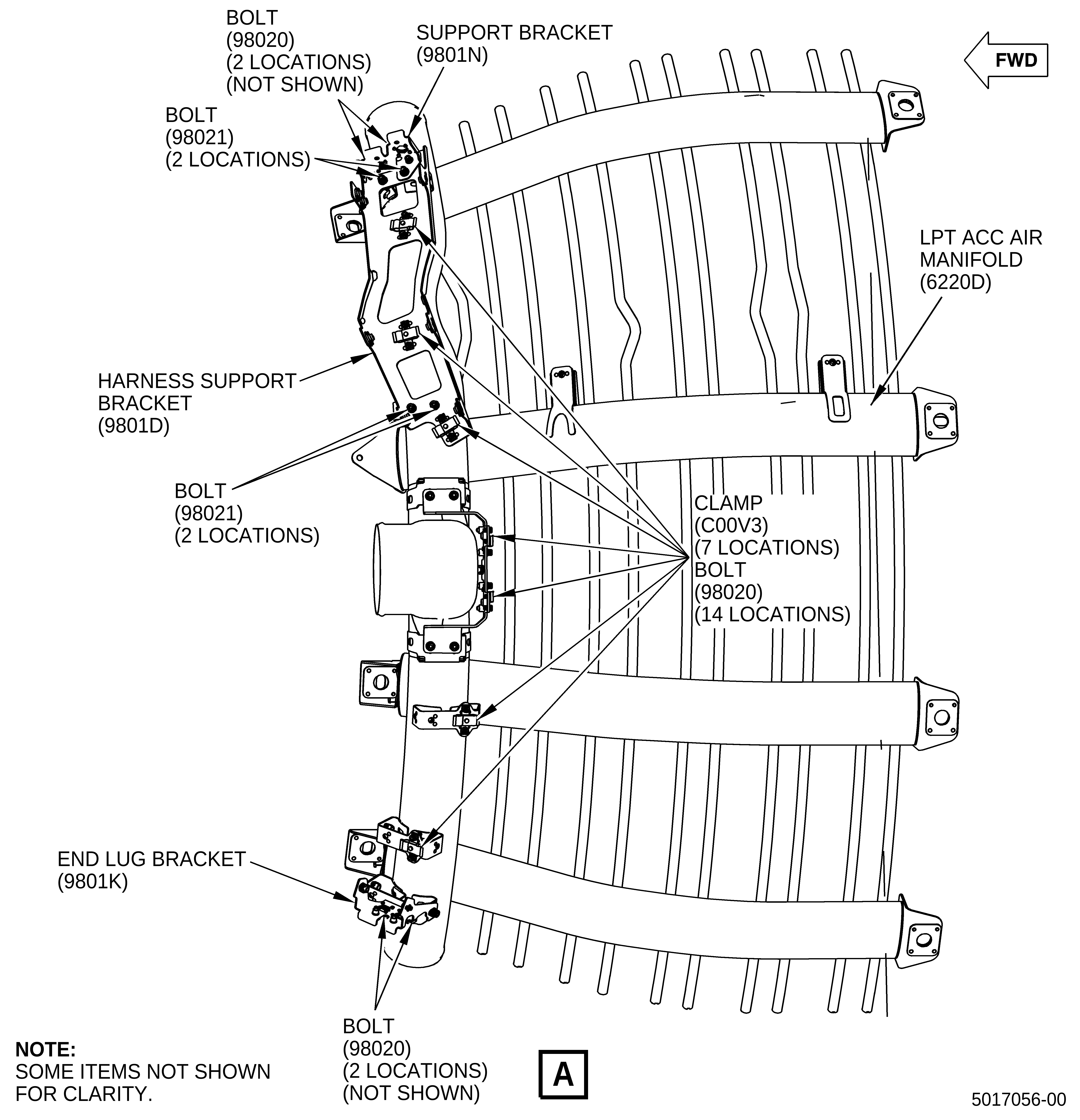
| (a) | Install the new support brackets for the left hand (L/H) fire detectors. Refer to Figure 1, Sheet 2, and do as follows: |
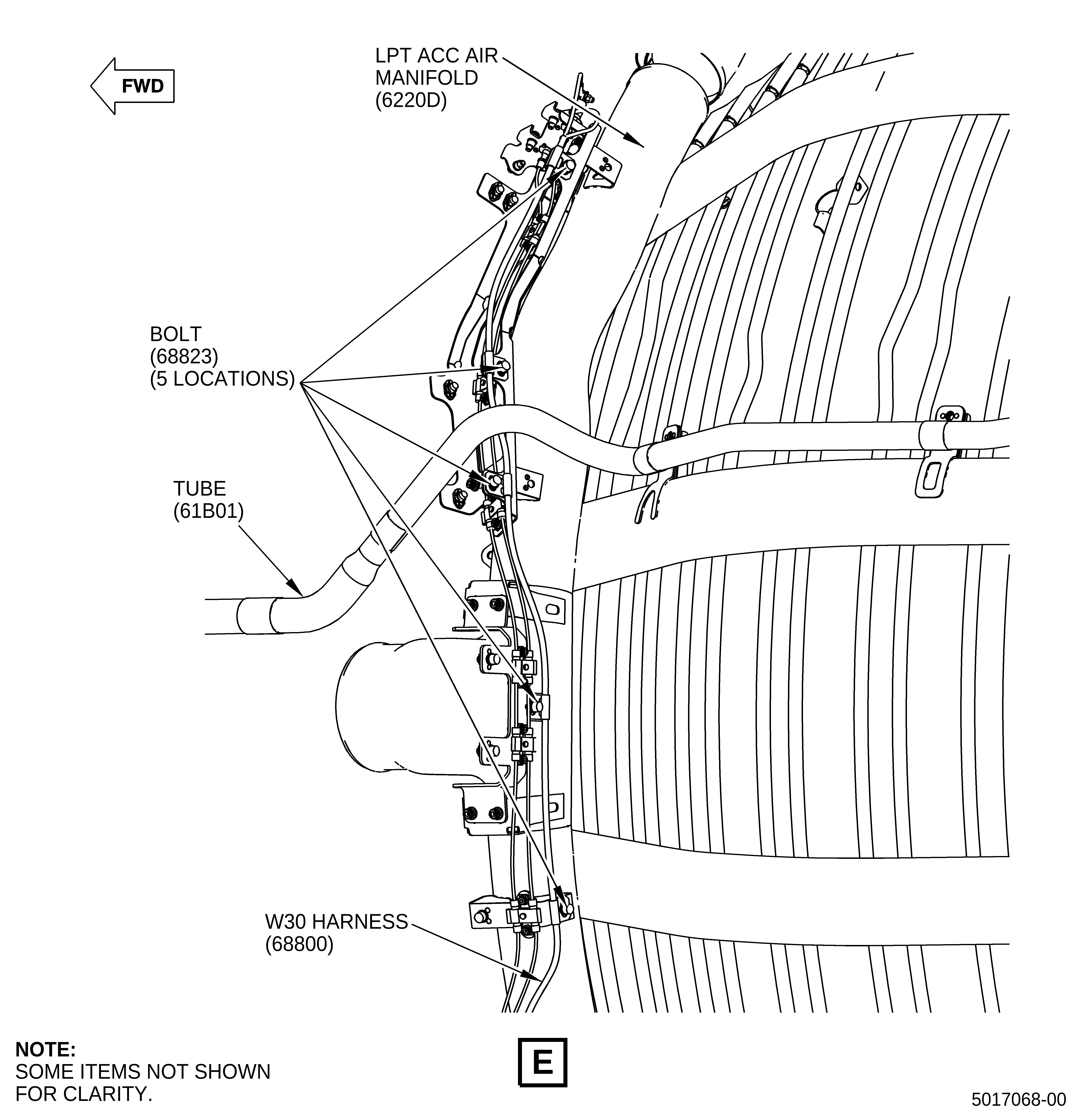
| 1 | Install the harness support bracket (SIN 9801D) to the L/H side forward looking aft (FLA) of the LPT ACC air manifold (SIN 6220D) with three bolts (SIN 98021). |
| 2 | Install the support bracket (SIN 9801N) to the top of the harness support bracket (SIN 9801D) with one bolt (SIN 98021) and two bolts (SIN 98020). |
| 3 | Torque the four bolts (SIN 98021) to 115 lb in. (13.0 N.m). |
| 4 | Torque the two bolts (SIN 98020) to 55 lb in. (6.2 N.m). |
| 5 | Install the end lug bracket (SIN 9801K) to the right hand (R/H) side (FLA) of the LPT ACC air manifold (SIN 6220D) with two bolts (SIN 98020). |
| 6 | Torque the two bolts (SIN 98020) to 55 lb in. (6.2 N.m). |
| (b) | Install the clamps (SIN C00V3) for the L/H fire detectors. Refer to Figure 1, Sheet 2, and do as follows: |
| 1 | Install the seven clamps (SIN C00V3) with 14 bolts (SIN 98020) (two for each clamp). |
| 2 | Torque the 14 bolts (SIN 98020) to 55 lb in. (6.2 N.m). |
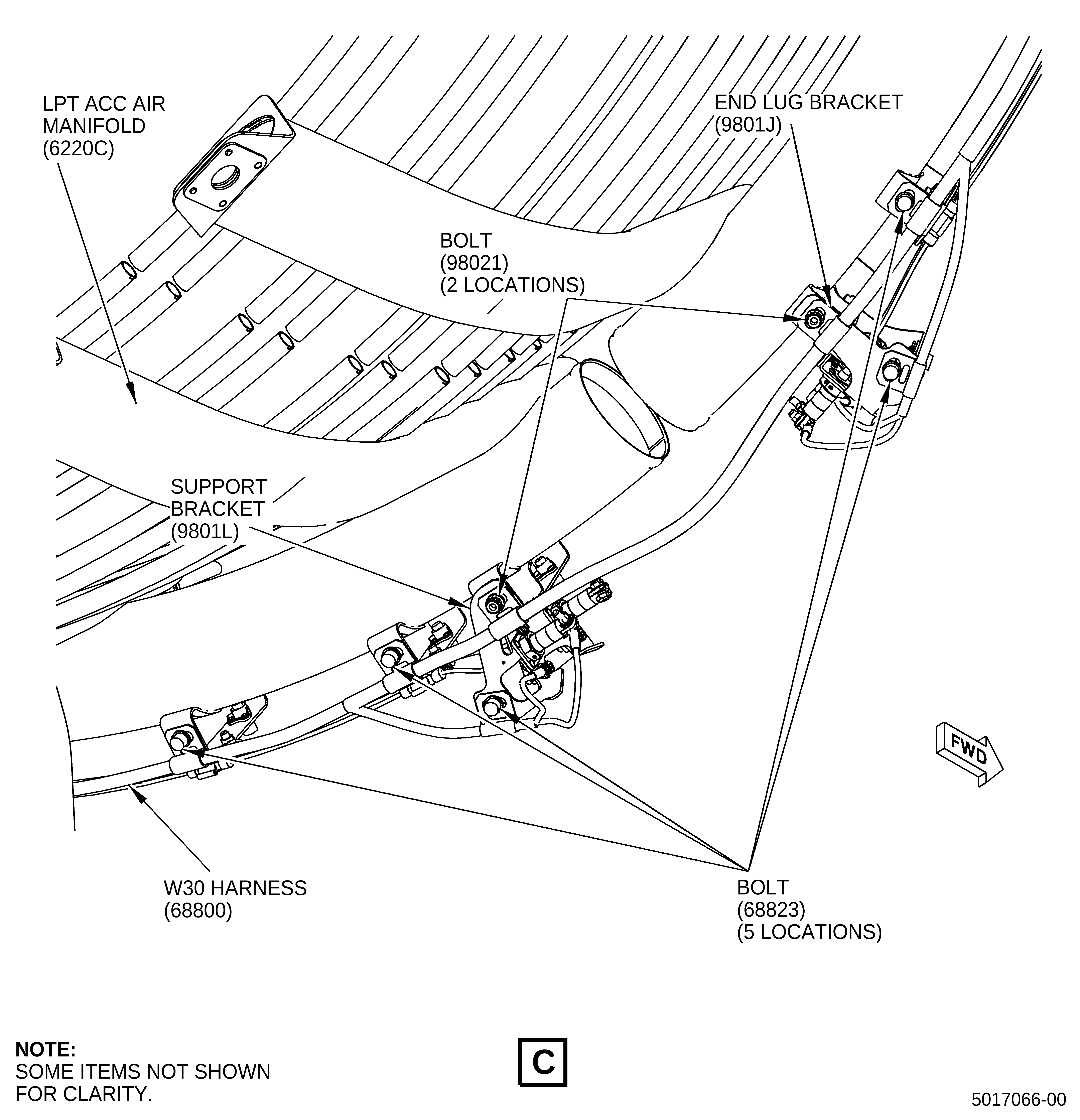
| (c) | Install the new support brackets for the lower fire detectors. Refer to Figure 1, Sheet 3, and do as follows: |
| 1 | Install the drain support bracket (SIN 9801F) to the L/H side (FLA) of the LPT ACC air manifold (SIN 6220C) with four bolts (SIN 98021). |
| 2 | Torque the four bolts (SIN 98021) to 115 lb in. (13.0 N.m). |
| 3 | Install the end lug bracket (SIN 9801J) to the L/H side (FLA) of the LPT ACC air manifold (SIN 6220C) with two bolts (SIN 98020). |
| 4 | Install the support bracket (SIN 9801L) to the R/H side (FLA) of the LPT ACC air manifold (SIN 6220C) with two bolts (SIN 98020). |
| 5 | Torque the four bolts (SIN 98020) to 55 lb in. (6.2 N.m). |
| (d) | Install the clamps (SIN C00V3) for the lower fire detectors. Refer to Figure 1, Sheet 3, and do as follows: |
| 1 | Install the seven clamps (SIN C00V3) with 14 bolts (SIN 98020) (two for each clamp). |
| 2 | Torque the 14 bolts (SIN 98020) to 55 lb in. (6.2 N.m). |
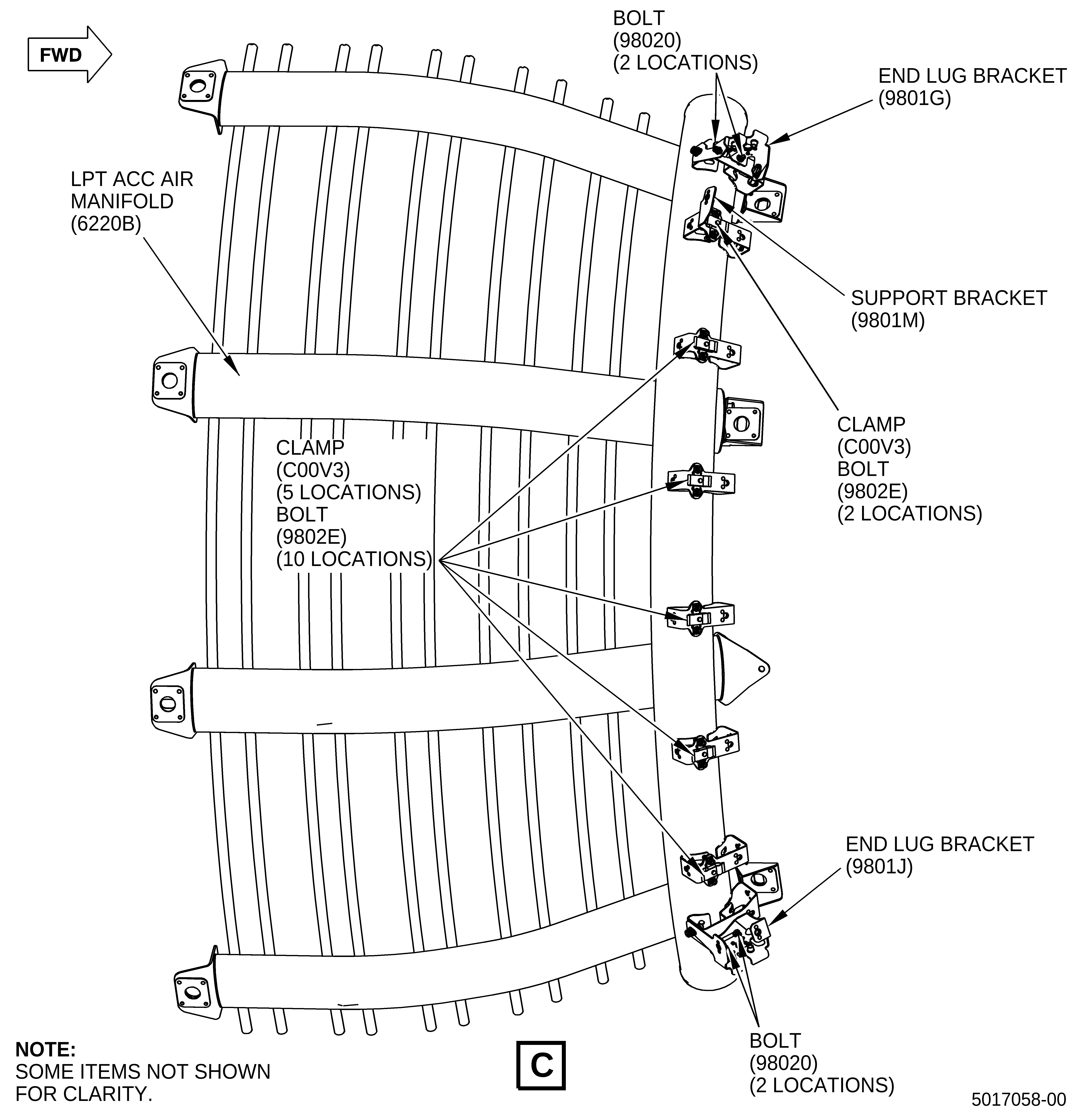
| (e) | Install the support brackets for the lower right fire detectors. Refer to Figure 1, Sheet 4, and do as follows: |
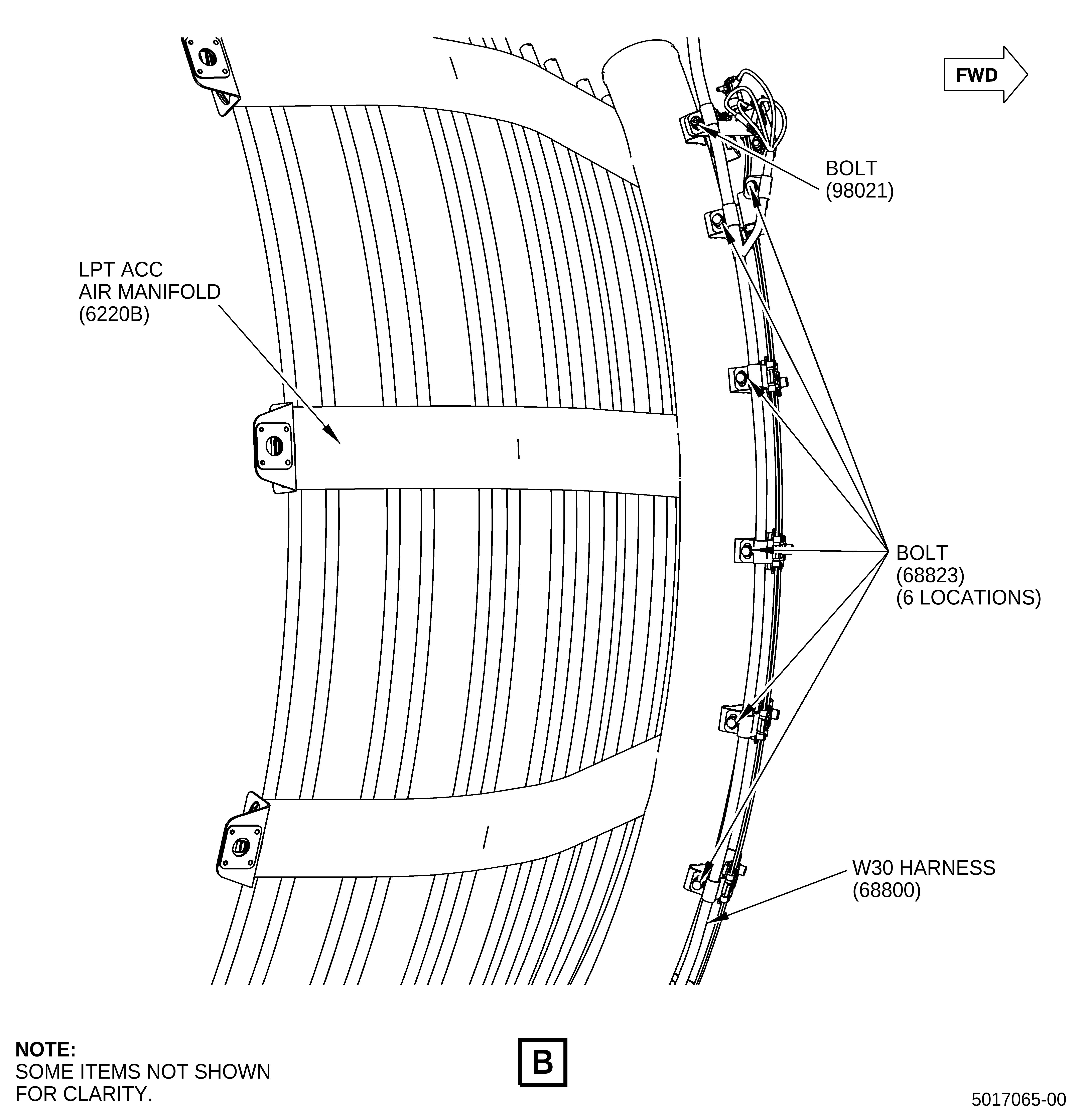
| 1 | Install the end lug bracket (SIN 9801J) to the L/H side (FLA) of the LPT ACC air manifold (SIN 6220B) with two bolts (SIN 98020). |
| 2 | Install the end lug bracket (SIN 9801G) to the R/H side (FLA) of the LPT ACC air manifold (SIN 6220B) with two bolts (SIN 98020). |
| 3 | Torque the four bolts (SIN 98020) to 55 lb in. (6.2 N.m). |
| (f) | Install the support bracket and clamps for the right fire detectors. Refer to Figure 1, Sheet 4, and do as follows: |
| 1 | Install the support bracket (SIN 9801M), with the clamp (SIN C00V3) on top, to the R/H side (FLA) of the LPT ACC air manifold (SIN 6220B) with two bolts (SIN 9802E). |
| 2 | Make sure that the cam-lock tab in the support bracket (SIN 9801M) points aft. |
| 3 | Install the five clamps (SIN C00V3) on the LPT ACC air manifold (SIN 6220B) with ten bolts (SIN 98020) (two for each clamp). |
| 4 | Torque the two bolts (SIN 9802E) and ten bolts (SIN 98020) to 55 lb in. (6.2 N.m). |
| (2) | Install the sensing elements. Refer to Figure 2 and do as follows: |
| (a) | Install the left sensing elements (SIN C00A7). Refer to Figure 2, Sheet 2, and do as follows: |
| 1 | Unwind and make sure that the two sensing element (SIN C00A7) leads are straight. Then, install 14 red grommets (SIN C00N7) (seven red grommets on each lead). |
| 2 | Install the sensing element (SIN C00A7) lead to the support bracket (SIN 9801N) with the No. 10 lug in the aft hole at the L/H side (FLA) of the LPT ACC air manifold. Rotate the sensing element as shown and attach the lead with one nut (SIN C00K2). |
| 3 | Install the sensing element (SIN C00A7) lead to the support bracket (SIN 9801N) with the No. 8 lug in the forward hole at the L/H side (FLA) of the LPT ACC air manifold. Rotate the sensing element as shown and attach the lead with one nut (SIN C00K2). |
| 4 | Make sure that the sensing element leads do not cross when they are routed to the R/H side. |
| NOTE: |
|
| 5 | Install the other end (aft) of the sensing element (SIN C00A7) lead to the aft hole of the end lug bracket (SIN 9801K). Rotate the sensing element as shown and attach the lead with one nut (SIN 00K2). |
| 6 | Install the other end (forward) of the sensing element (SIN C00A7) lead to the forward hole of the end lug bracket (SIN 9801K). Rotate the sensing element as shown and attach the lead with one nut (SIN C00K2). |
| 7 | Attach the sensing element (SIN C00A7) leads to the clamps (SIN C00V3) with a 3/16 inch nut driver. Do a 1/4 turn or until locked. Make sure to start at one end and continue to the other centering red grommets (SIN C00N7) and that the sensing element leads are kept parallel to each other and have a smooth contour. |
| 8 | Torque the four nuts (SIN C00K2) to 100 lb in. (11.3 N.m). |
| 9 | Safety the four nuts (SIN C00K2) to each other on each end with C10-143 safety cable or C10-071 safety wire. |
| (b) | Install the lower sensing elements (SIN C00A7). Refer to Figure 2, Sheet 3, and do as follows: |
| 1 | Unwind and make sure that the two sensing element (SIN C00A7) leads are straight. Then, install 14 red grommets (SIN C00N7) (seven red grommets on each lead). |
| 2 | Install the sensing element (SIN C00A7) lead to the end lug bracket (SIN 9801J) with the No. 10 lug in the aft hole at the L/H side (FLA) of the LPT ACC air manifold. Rotate the sensing element as shown and attach the lead with one nut (SIN C00K2). |
| 3 | Install the sensing element (SIN C00A7) lead to the end lug bracket (SIN 9801J) with the No. 8 lug in the forward hole at the L/H side (FLA) of the LPT ACC air manifold. Rotate the sensing element as shown and attach the lead with one nut (SIN C00K2). |
| 4 | Make sure that the sensing element leads do not cross when they are routed to the R/H side (FLA). |
| NOTE: |
|
| 5 | Install the other end (forward) of the of the sensing element lead to the forward hole of the support bracket (SIN 9801L). Rotate the sensing element as shown and attach the lead with one nut (SIN C00K2). |
| 6 | Install the other end (aft) of the sensing element lead to the aft hole of the support bracket (SIN 9801L). Rotate the sensing element as shown and attach the lead with one nut (SIN C00K2). |
| 7 | Attach the sensing element (SIN C00A7) leads to the clamps (SIN C00V3) with a 3/16 inch nut driver. Do a 1/4 turn or until locked. Make sure to start at one end and continue to the other centering red grommets (SIN C00N7) and that the sensing element leads are kept parallel to each other and have a smooth contour. |
| 8 | Torque the four nuts (SIN C00K2) to 100 lb in. (11.3 N.m). |
| 9 | Safety the four nuts (SIN C00K2) to each other on each end with C10-143 safety cable or C10-071 safety wire. |
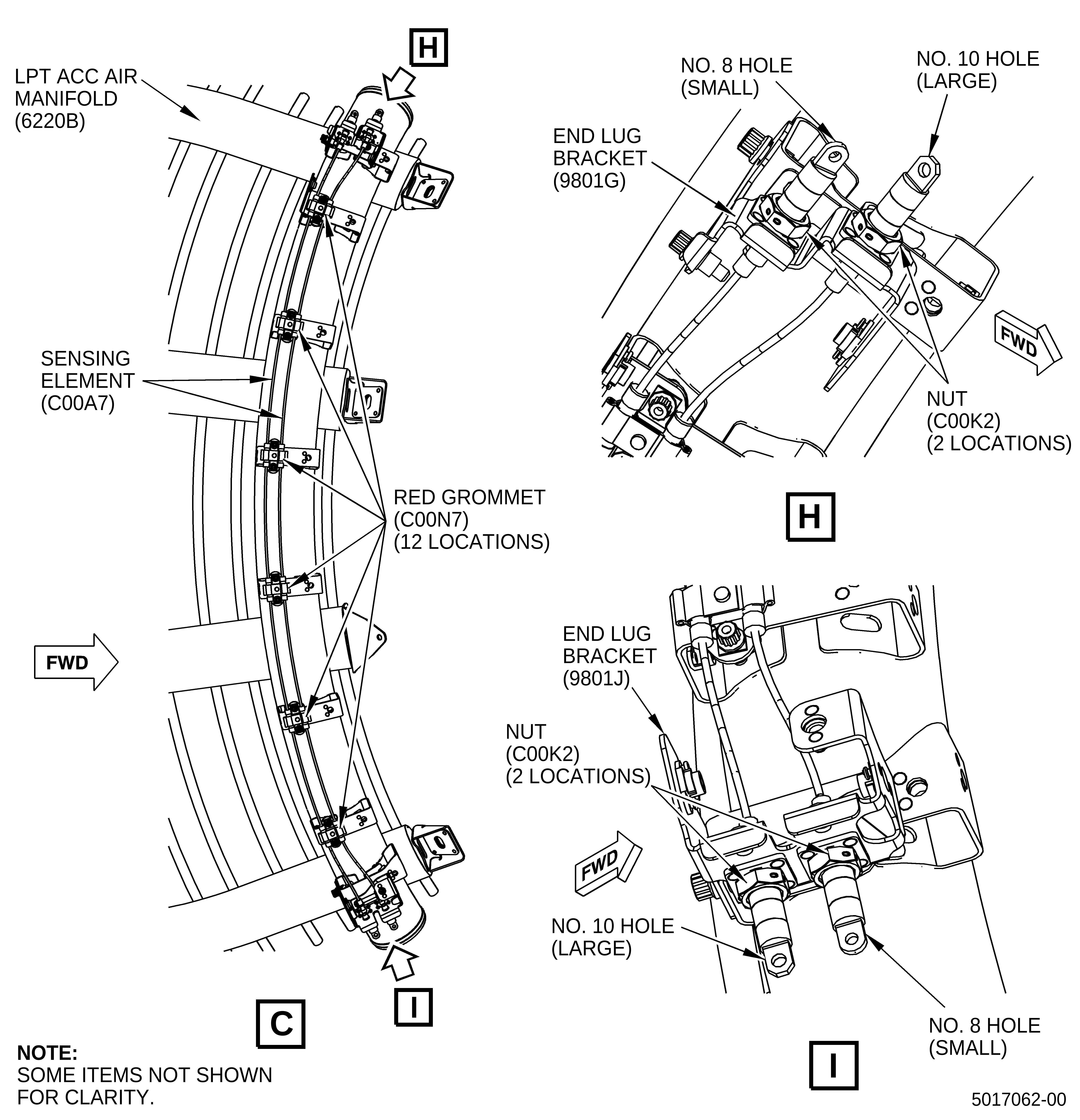
| (c) | Install the right sensing elements (SIN C00A7). Refer to Figure 2, Sheet 4, and do as follows: |
| 1 | Unwind and make sure that the two sensing element (SIN C00A7) leads are straight. Then, install 12 red grommets (SIN C00N7) (six red grommets on each lead). |
| 2 | Install the sensing element (SIN C00A7) lead to the end lug bracket (SIN 9801J) with the No. 8 lug in the forward hole at the L/H side (FLA) of the LPT ACC air manifold. Rotate the sensing element as shown and attach the lead with one nut (SIN C00K2). |
| 3 | Install the sensing element (SIN C00A7) lead to the end lug bracket (SIN 9801J) with the No. 10 lug in the aft hole at the L/H side (FLA) of the LPT ACC air manifold. Rotate the sensing element as shown and attach the lead with one nut (SIN C00K2). |
| 4 | Make sure that the sensing element leads do not cross when they are routed to the R/H side (FLA). |
| NOTE: |
|
| 5 | Install the other end (forward) of the sensing element lead to the forward hole of the end lug bracket (SIN 9801G). Rotate the sensing element as shown and attach the lead with one nut (SIN C00K2). |
| 6 | Install the other end (aft) of the sensing element lead to the aft hole of the end lug bracket (SIN 9801G). Rotate the sensing element as shown and attach the lead with one nut (SIN C00K2). |
| 7 | Attach the sensing element (SIN C00A7) leads to the clamps (SIN C00V3) with a 3/16 inch nut driver. Do a 1/4 turn or until locked. Make sure to start at one end and continue to the other centering red grommets (SIN C00N7) and that the sensing element leads are kept parallel to each other and have a smooth contour. |
| 8 | Torque the four nuts (SIN C00K2) to 100 lb in. (11.3 N.m). |
| 9 | Safety the four nuts (SIN C00K2) to each other on each end with C10-143 safety cable or C10-071 safety wire. |
| (3) | Install the W30 and W31 harnesses as follows: |
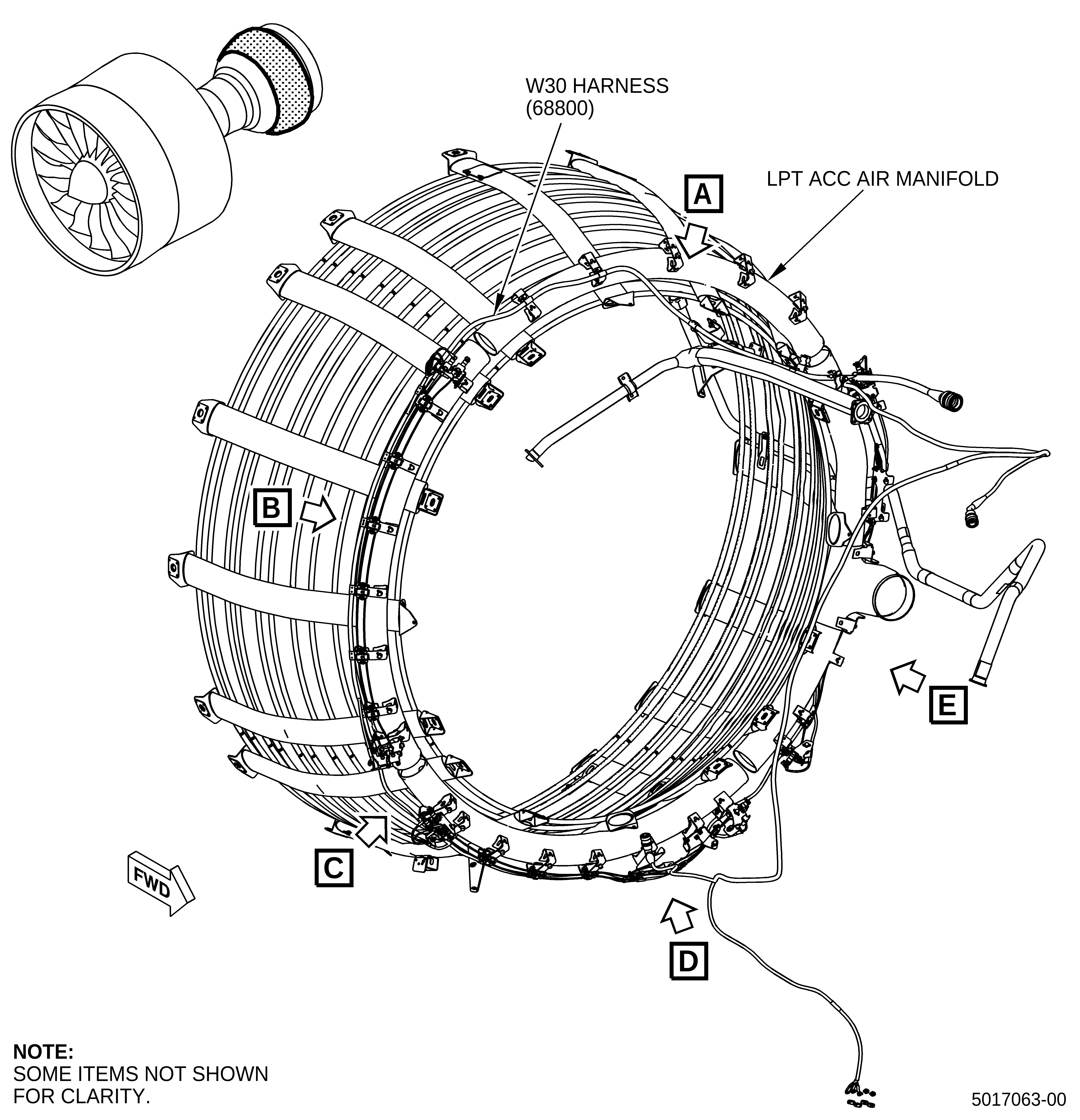
| (a) | Use one bolt (SIN 68823) to attach the blue-violet W30 harness (SIN 68800) to the bracket (SIN 6881D) at the 12:00 o'clock position of the LPT ACC air manifold (SIN 6220B). Make sure that the routing of the W30 harness (SIN 68800) goes down in the R/H side of the LPT ACC air manifold (SIN 6220A). Refer to Figure 3, Sheet 2. |
| (b) | Attach the W30 harness (SIN 68800) with two bolts (SIN 68823) between the 1:00 and 2:00 o'clock positions of the LPT ACC air manifold (SIN 6220A). Refer to Figure 3, Sheet 2. |
| (c) | Attach the W30 harness (SIN 68800) to the end lug bracket (SIN 9801G) with one bolt (SIN 98021). Refer to Figure 3, Sheet 3. |
| (d) | Attach the W30 harness (SIN 68800) with six bolts (SIN 68823) between the 2:30 and 5:45 o'clock positions. Refer to Figure 3, Sheet 3. |
| (e) | Attach the W30 harness (SIN 68800) to the support bracket (SIN 9801L) and end lug bracket (SIN 9801J) with two bolts (SIN 98021). Refer to Figure 3, Sheet 4. |
| (f) | Attach the W30 harness (SIN 68800) with five bolts (SIN 68823) between the 4:15 and 5:45 o'clock positions. Refer to Figure 3, Sheet 4. |
| (g) | Attach the W30 harness (SIN 68800) to the end lug brackets (SIN 9801J) and (SIN 9801K) with two bolts (SIN 98021). Refer to Figure 3, Sheet 5. |
| (h) | Attach the W30 harness (SIN 68800) with seven bolts (SIN 68823) between the 6:00 and 8:00 o'clock positions. Refer to Figure 3, Sheet 5. |
| (i) | Attach the W30 harness (SIN 68800) with five bolts (SIN 68823) between the 8:45 and 10:00 o'clock positions. Refer to Figure 3, Sheet 6. |
| (j) | Make sure to route the W30 harness (SIN 68800) under the tube (SIN 61B01). |
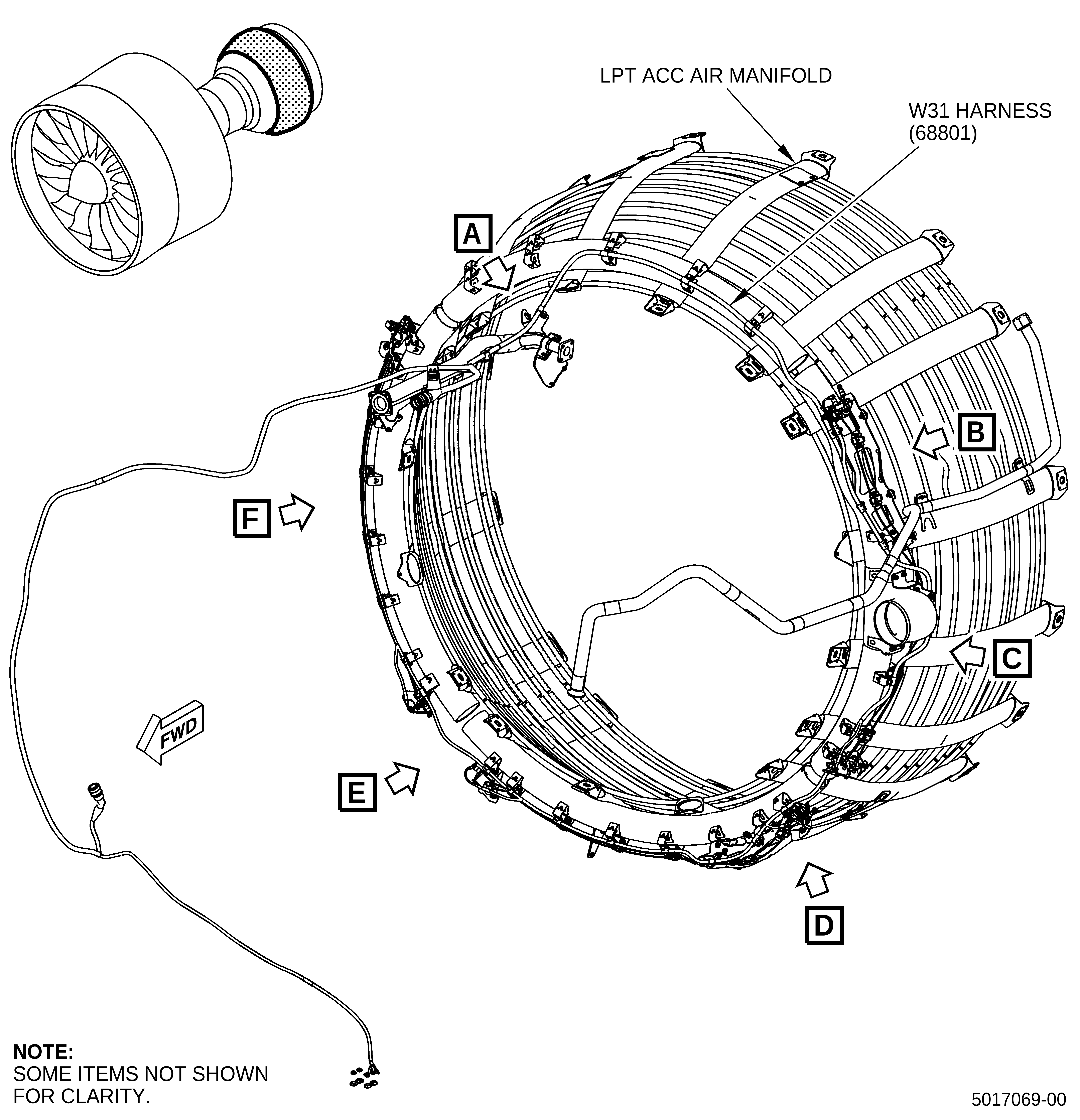
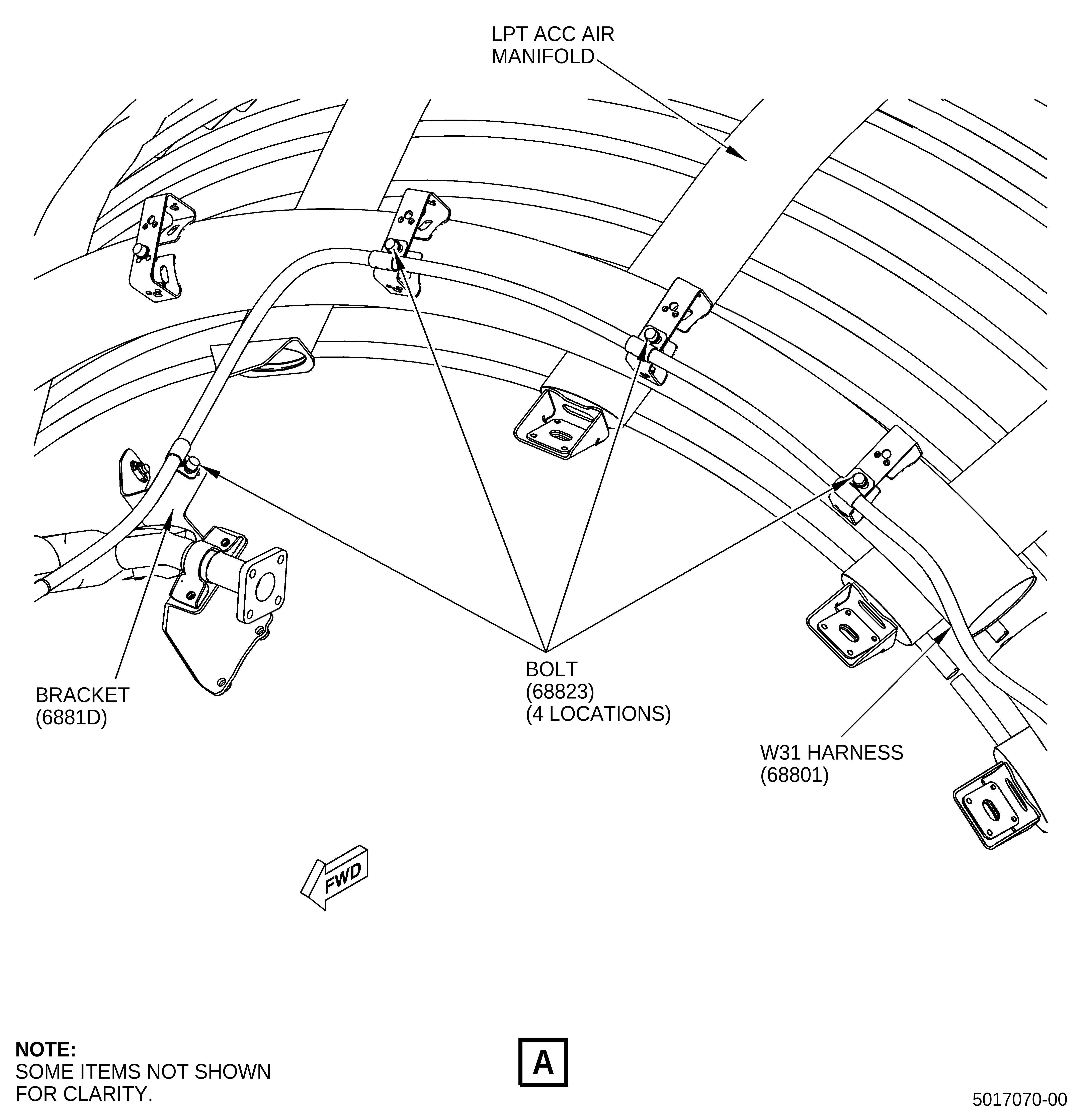
| (k) | Attach the blue-orange W31 harness (SIN 68801) to the bracket (SIN 6881D) at the 12:00 o'clock position with one bolt (SIN 68823). Refer to Figure 4, Sheet 2. |
| (l) | Attach the W31 harness (SIN 68801) between the 11:45 and 11:00 o'clock positions with three bolts (SIN 68823). Refer to Figure 4, Sheet 2. |
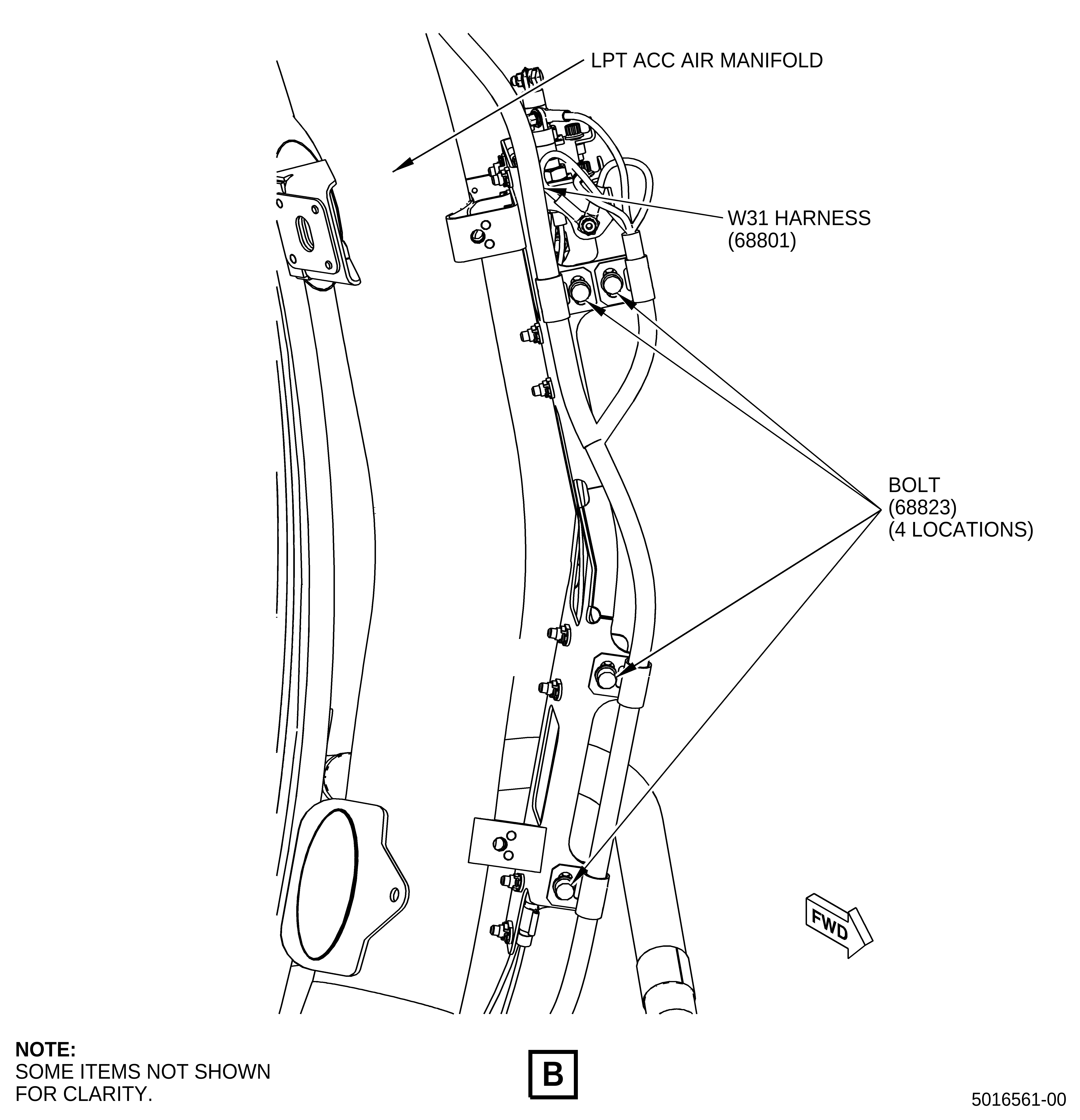
| (m) | Attach the W31 harness (SIN 68801) between the 10:15 and 9:15 o'clock positions with four bolts (SIN 68823). Refer to Figure 4, Sheet 3. |
| (n) | Attach the W31 harness (SIN 68801) between the 9:00 and 8:30 o'clock positions with three bolts (SIN 68823). Refer to Figure 4, Sheet 4. |
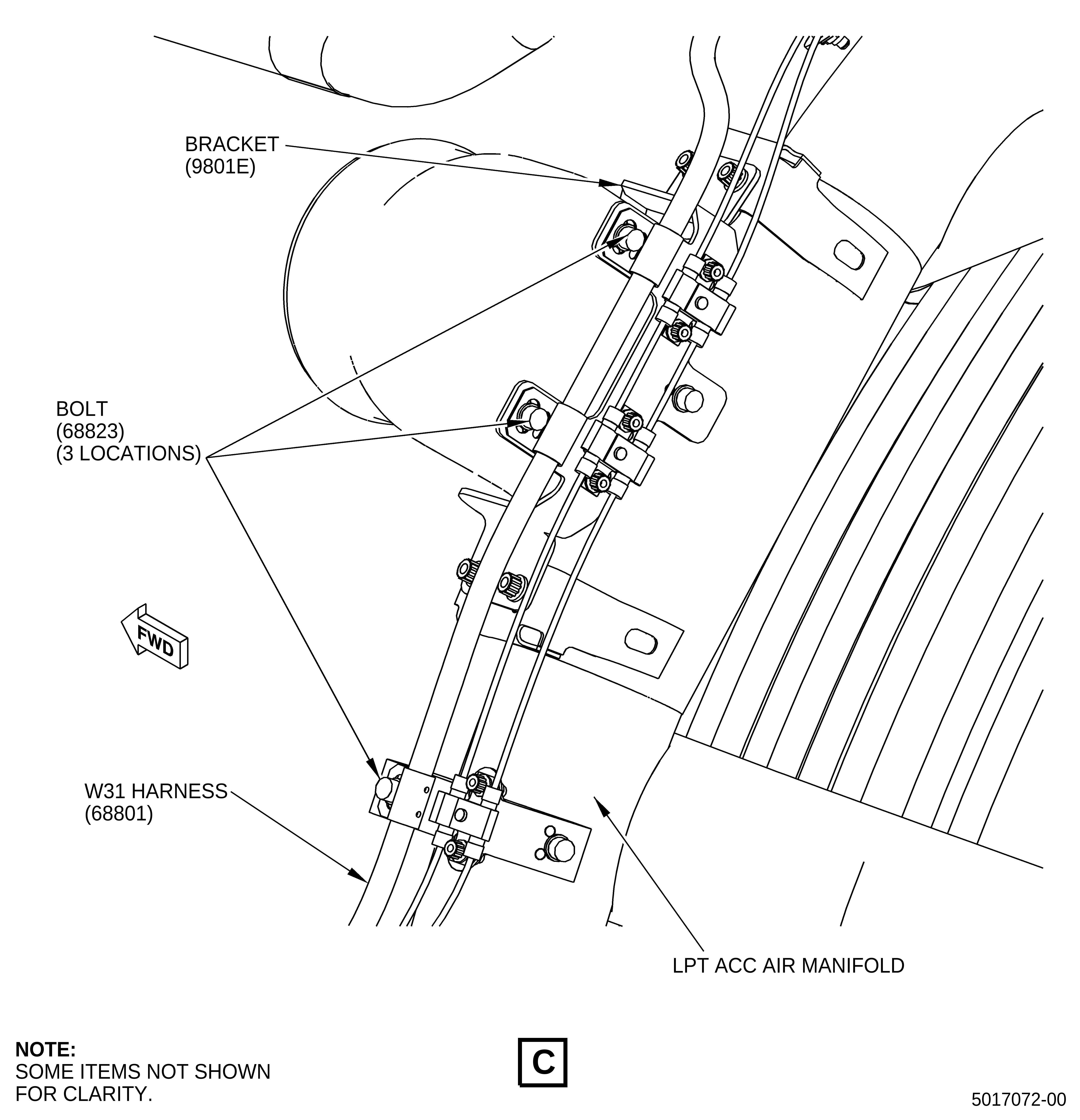
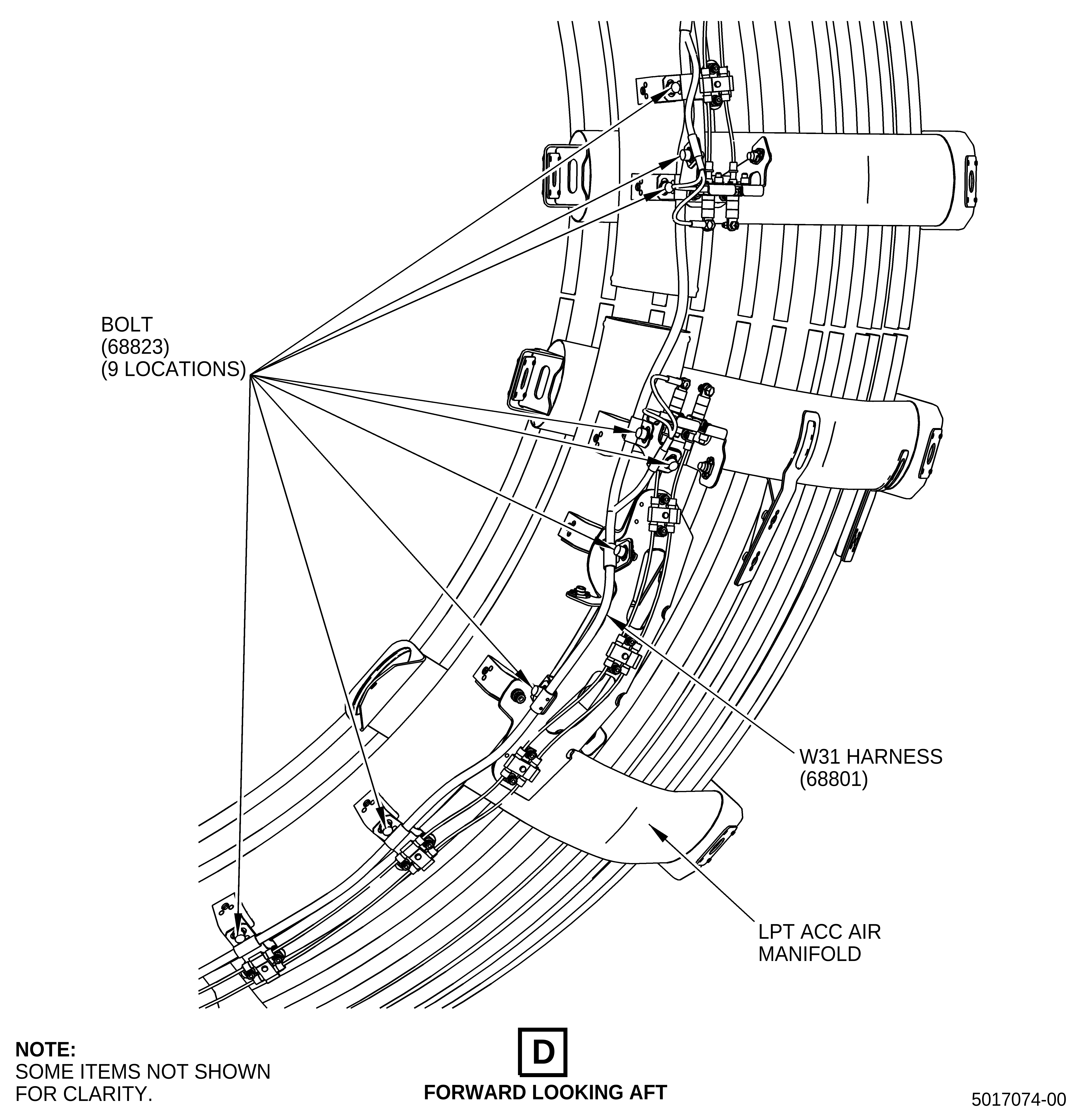
| (o) | Attach the W31 harness (SIN 68801) between the 8:00 and 6:30 o'clock positions with nine bolts (SIN 68823). Refer to Figure 4, Sheet 5. |
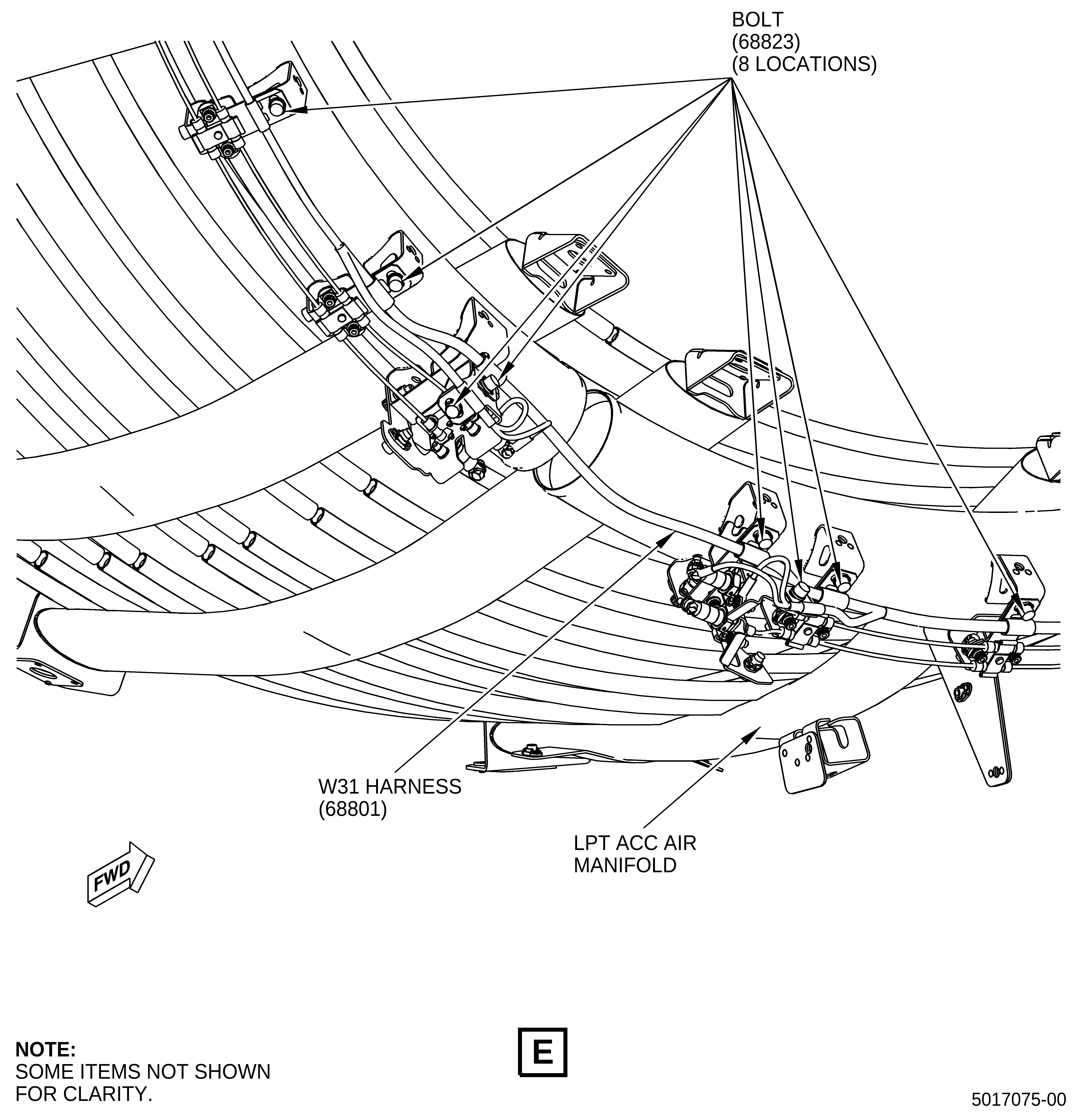
| (p) | Attach the W31 harness (SIN 68801) between the 6:00 and 4:00 o'clock positions with eight bolts (SIN 68823). Refer to Figure 4, Sheet 6. |
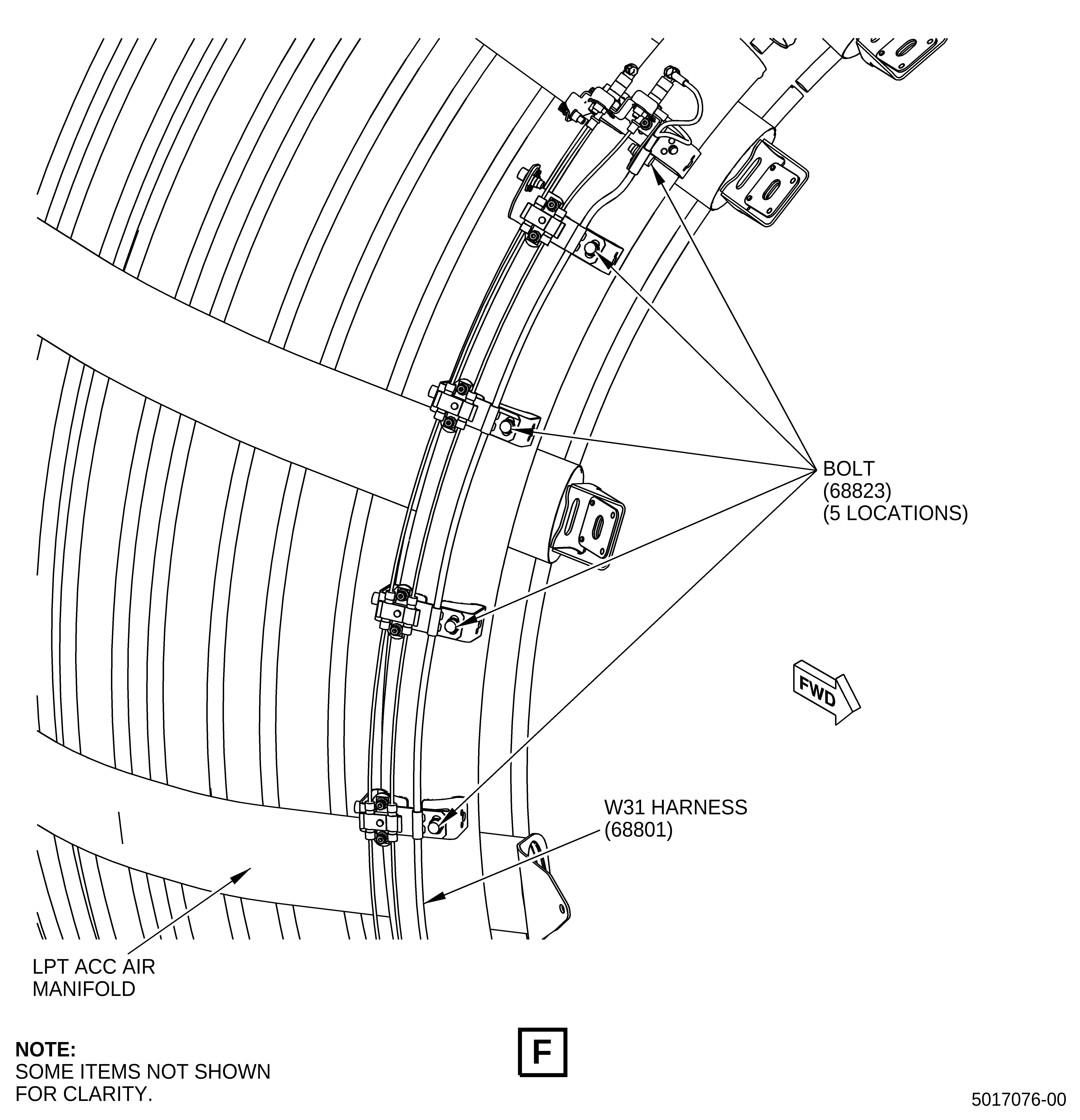
| (q) | Attach the W31 harness (SIN 68801) between the 3:15 and 1:45 o'clock positions with five bolts (SIN 68823). Refer to Figure 4, Sheet 7. |
| (r) | Attach the W30 and W31 harnesses to the oil vent manifold (SIN 46101) spring clips. Refer to Figure 5, Sheet 1. |
| (s) | Attach the W30 and W31 harnesses to the oil tube (SIN 46100) spring clips. Refer to Figure 5, Sheet 2. |
| (t) | Attach the W31 harness (SIN 68801) (blue-orange) to the oil vent manifold (SIN 46101) spring clips. Refer to Figure 5, Sheet 2. |
| (u) | Attach the W30 harness (SIN 68800) (blue-violet) to the oil tube (SIN 46100) spring clip with one insert (SIN 68837). Refer to Figure 5, Sheet 2. |
| (v) | Attach the W31 harness (SIN 68801) (blue-orange) to the oil tube (SIN 46100) spring clip. Refer to Figure 5, Sheet 3. |
| (w) | Attach the W30 harness (SIN 68800) (blue-violet) P303 lead to the oil tube (SIN 46100) spring clip. Refer to Figure 5, Sheet 3. |
| (x) | Attach the W30 and W31 harnesses to the cowl support bracket and EAI controller as follows: |
| 1 | Put the W30 harness (SIN 68800) (blue-violet) P303 lead under the W31 harness (SIN 68801) (blue-orange) and connect to the EAI controller (SIN C00AD). Refer to Figure 5, Sheet 4. |
| 2 | Tighten the W30 harness (SIN 68800) (blue-violet) P303 lead with cannon plug pliers. Refer to Figure 5, Sheet 4. |
| 3 | Put the W31 harness (SIN 68801) (blue-orange) under the blue-green cable and attach it to the two lower forward spring clips of the control cables support bracket (SIN 68816). Refer to Figure 5, Sheet 4. |
| 4 | Attach the W30 harness (SIN 68800) (blue-violet) to the two upper aft spring clips of the control cables support bracket (SIN 68816). Refer to Figure 5, Sheet 5. |
| (y) | Attach the W30 and W31 harnesses to the cowl support brackets as follows: |
| 1 | Attach the W30 and W31 harnesses to the support bracket (SIN 53012). Refer to Figure 5, Sheet 6, and do as follows: |
| a | Attach the W30 harness (SIN 68800) to the middle clip. |
| b | Attach the W31 harness (SIN 68801) to the forward clip. |
| 2 | Attach the W30 and W31 harnesses to the inboard clips of the support bracket (SIN 6711B) . Refer to Figure 5, Sheet 7, and do as follows: |
| a | Attach the W30 harness (SIN 68800) to the aft clip. |
| b | Attach the W31 harness (SIN 68801) to the forward clip. |
| 3 | Attach the W30 and W31 harnesses to the inboard clips of the support bracket (SIN 6711C) . Refer to Figure 5, Sheet 7, and do as follows: |
| a | Attach the W30 harness (SIN 68800) to the aft clip. |
| b | Attach the W31 harness (SIN 68801) to the forward clip. |
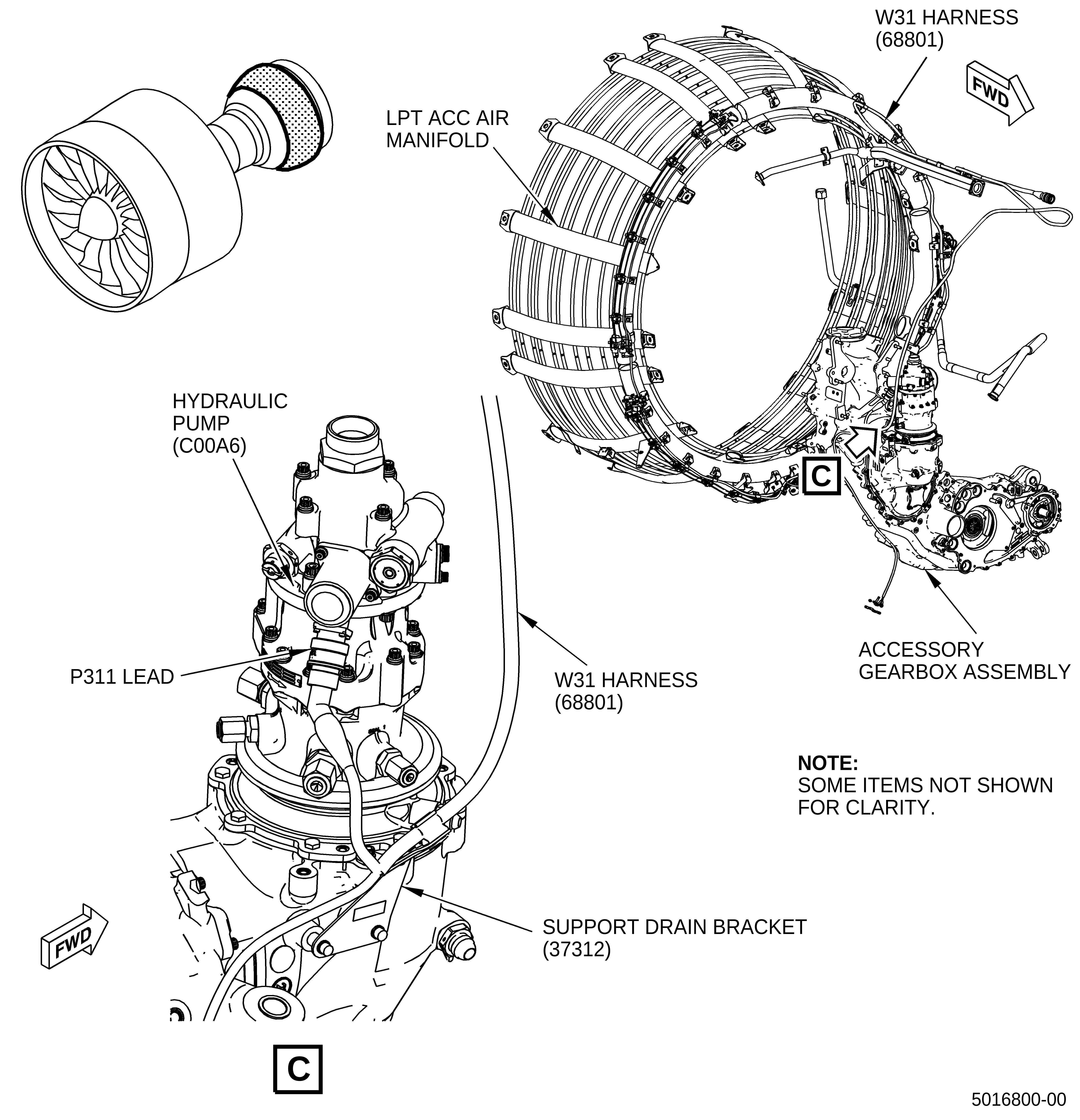
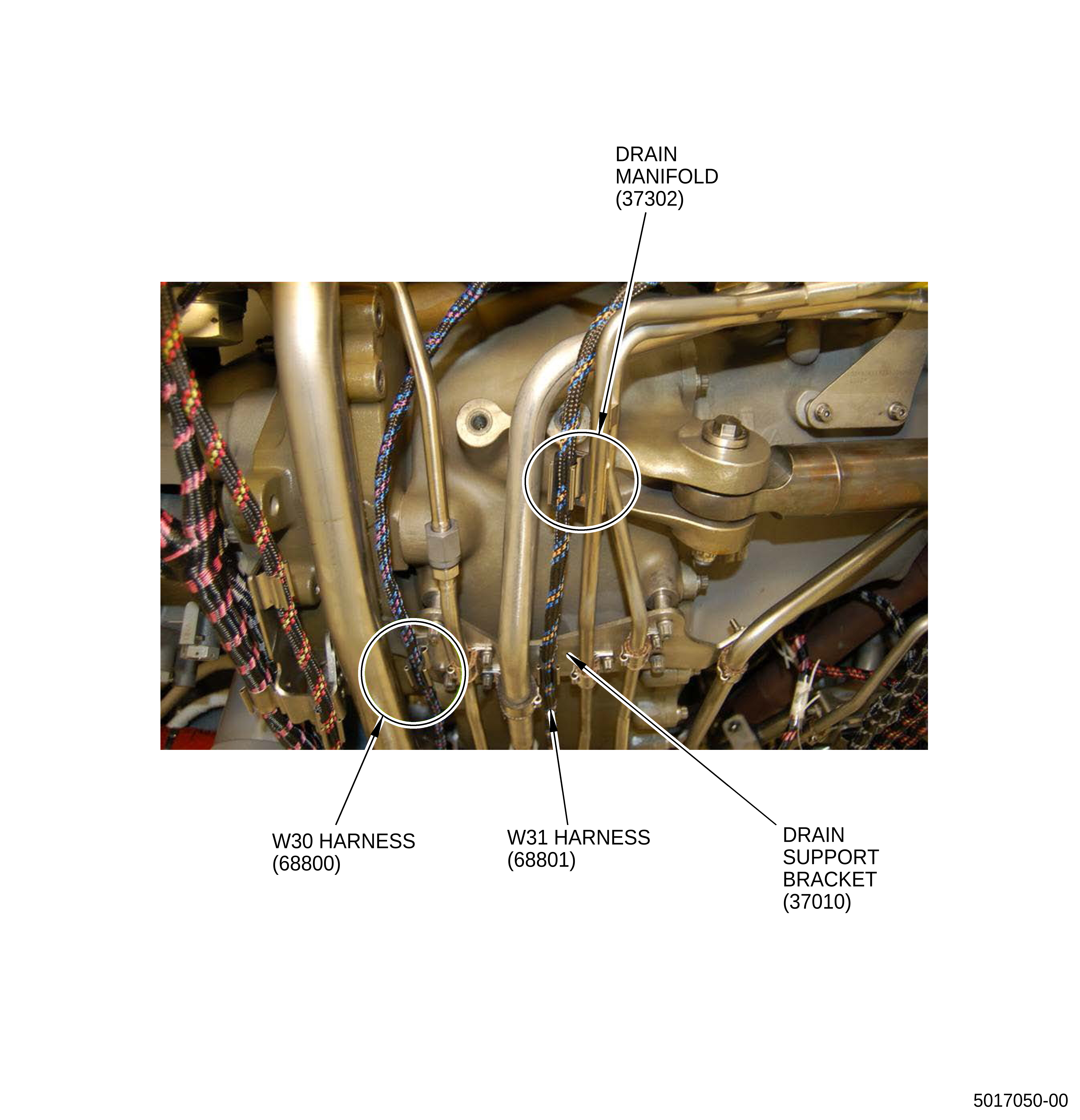
| 4 | Attach the W31 harness (SIN 68801) (blue-orange) to the clip on the support drain bracket (SIN 37312) and hydraulic pump (SIN C00A6). Refer to Figure 5, Sheet 8. |
| a | Put the W31 harness (SIN 68801) in the clip on the support drain bracket (SIN 37312). |
| b | Connect the P311 lead to the hydraulic pump (SIN C00A6). |
| c | Tighten the P311 lead to the hydraulic pump (SIN C00A6) with cannon plug pliers. |
| 5 | Attach the W31 harness (SIN 68801) (blue-orange) to the inboard clip of the drain manifold (SIN 37302) with one insert (SIN 68834). Refer to Figure 5, Sheet 9. |
| 6 | Put the W30 harness (SIN 68800) (blue-violet) inboard of the W31 harness (SIN 68801) (blue-orange) and attach it to the inboard clip of the drain tube (SIN 59001). Refer to Figure 5, Sheet 9. |
| (z) | Attach the W30 and W31 harnesses to the support brackets and the fuel metering unit (FMU) as follows: |
| 1 | Put the W30 harness (SIN 68800) (blue-violet) under the gray cable at the fuel flow meter position and attach it to the fuel tube (SIN 37610) clip. Refer to Figure 5, Sheet 10. |
| 2 | Connect the P301 lead to the forward port of the FMU (SIN 30000). Refer to Figure 5, Sheet 10. |
| 3 | Tighten the P301 lead to the FMU (SIN 30000) with cannon plug pliers. Refer to Figure 5, Sheet 10. |
| 4 | Put the W30 (blue-violet) on the inboard side of the tube and attach it to the aft clip of the drain support bracket (SIN 37010) with one insert (SIN 68834). Refer to Figure 5, Sheet 11. |
| 5 | Attach the W31 harness (SIN 68801) (blue-orange) to the clip on the drain manifold (SIN 37302) with one insert (SIN 68834). Refer to Figure 5, Sheet 11. |
| 6 | Attach the W31 harness (SIN 68801) (blue-orange) on the forward clip of the drain manifold (SIN 37302) with one insert (SIN 68834). Refer to Figure 5, Sheet 11. |
| (aa) | Attach the W30 and W31 harnesses to the support brackets and tubes: |
| 1 | Attach the W30 harness (SIN 68800) (blue-violet) to the clip of the MFP and TBV drain manifold (SIN 37000). Refer to Figure 5, Sheet 12. |
| 2 | Attach the W31 harness (SIN 68801) (blue-orange) to the forward clip of the drain support bracket (SIN 37011) with one insert (SIN 68834). Refer to Figure 5, Sheet 12. |
| 3 | Attach the W30 harness (SIN 68800) (blue-violet) to the aft inboard clip of the support bracket (SIN 6711G). Refer to Figure 5, Sheet 13. |
| 4 | Attach the W31 harness (SIN 68801) (blue-orange) to the forward inboard clip of the support bracket (SIN 6711G). Refer to Figure 5, Sheet 13. |
| (4) | Attach the W30 and W31 harness to the sensing elements. Refer to Figure 6 and do as follows: |
| NOTE: |
|
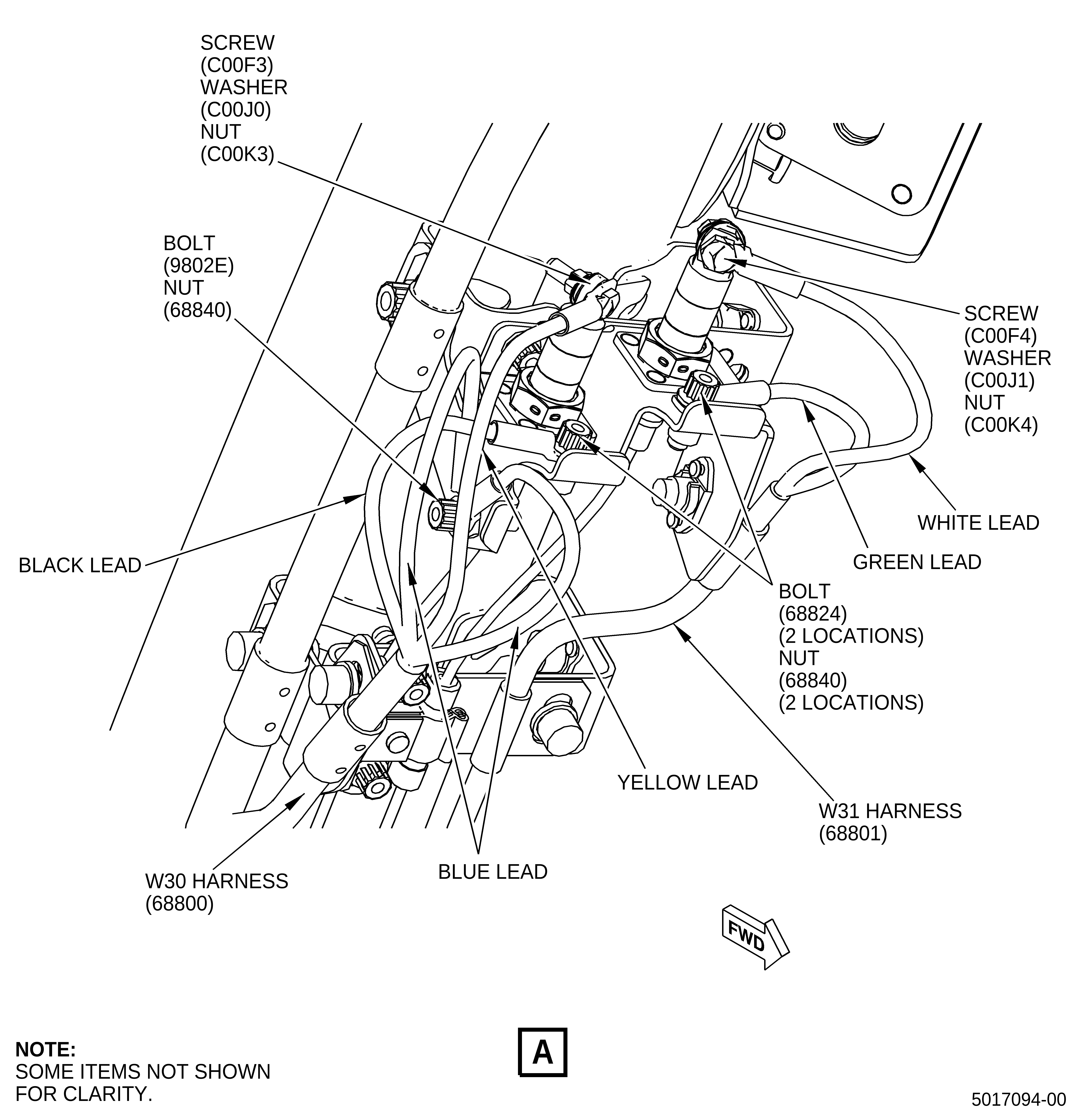
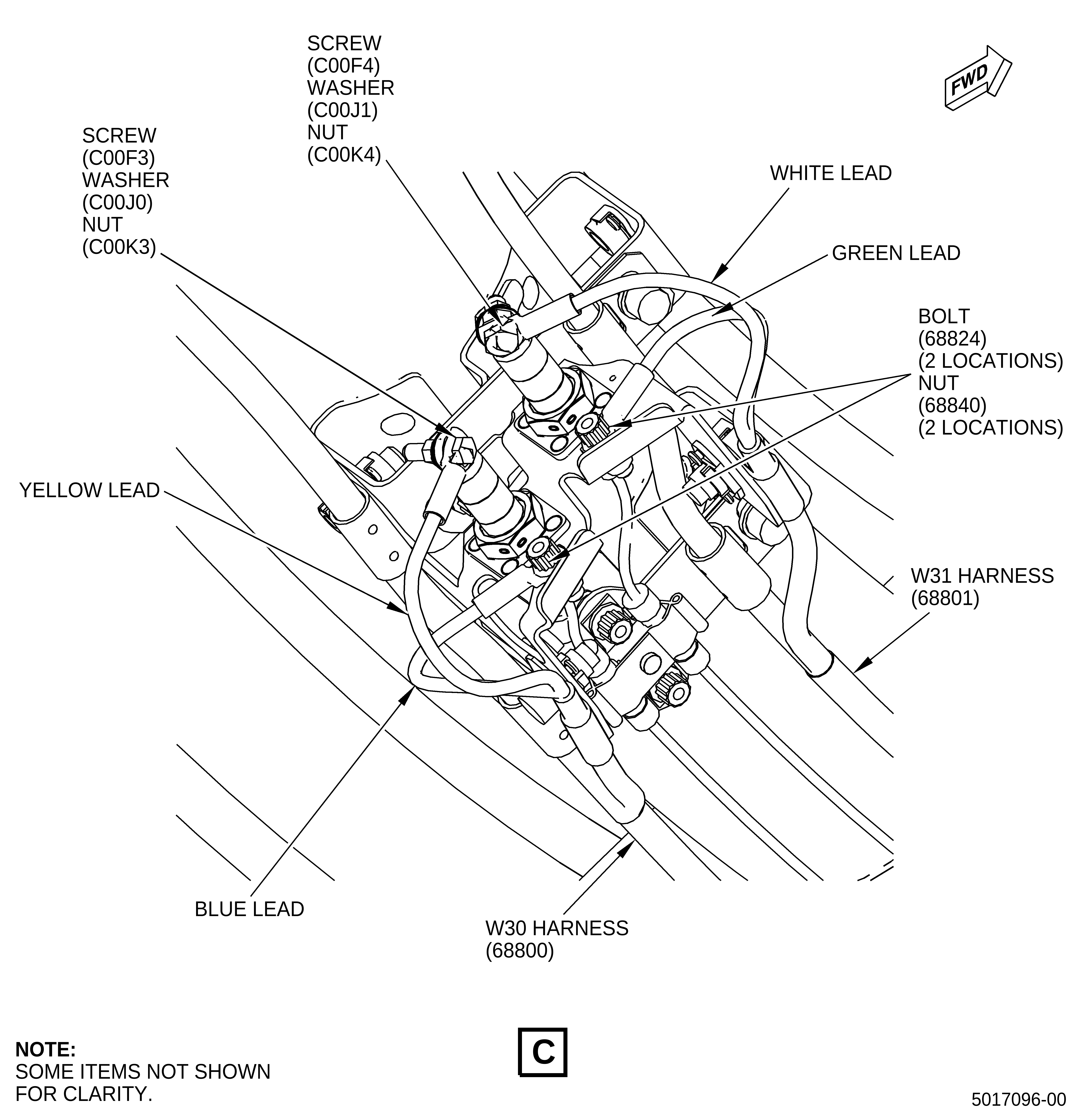
| (a) | Attach the sensing elements at the 1:45 o'clock position. Refer to Figure 6, Sheet 2, and do as follows: |
| 1 | Attach the W30 harness (SIN 68800) terminal ends on the L/H locations that follow: |
| a | Connect the two blue leads to ground with one bolt (SIN 9802E) and self-locking nut (nut) (SIN 68840) on the left side tab. |
| (1) | Torque the nut (SIN 68840) to 55 lb in. (6.2 N.m). |
| b | Connect the black lead to ground with one bolt (SIN 68824) and nut (SIN 68840) on the L/H outboard side. |
| (1) | Torque the nut (SIN 68840) to 55 lb in. (6.2 N.m). |
| c | Connect the yellow lead to the L/H sensing element with one No. 8 screw (screw) (SIN C00F3), washer (SIN C00J0) (under nut), and nut (SIN C00K3). |
| (1) | Torque the nut (SIN C00K3) to 25 lb in. (2.8 N.m). |
| 2 | Attach the W31 harness (SIN 68801) terminal ends on the R/H locations that follow: |
| a | Connect the green lead to ground with one bolt (SIN 68824) and nut (SIN 68840). |
| (1) | Torque the nut (SIN 68840) to 55 lb in. (6.2 N.m). |
| b | Connect the white lead to the R/H sensing element with one No. 10 screw (screw) (SIN C00F4), washer (SIN C00J1) (under nut), and nut (SIN C00K4). |
| (1) | Torque the nut (SIN C00K4) to 35 lb in. (4.0 N.m). |
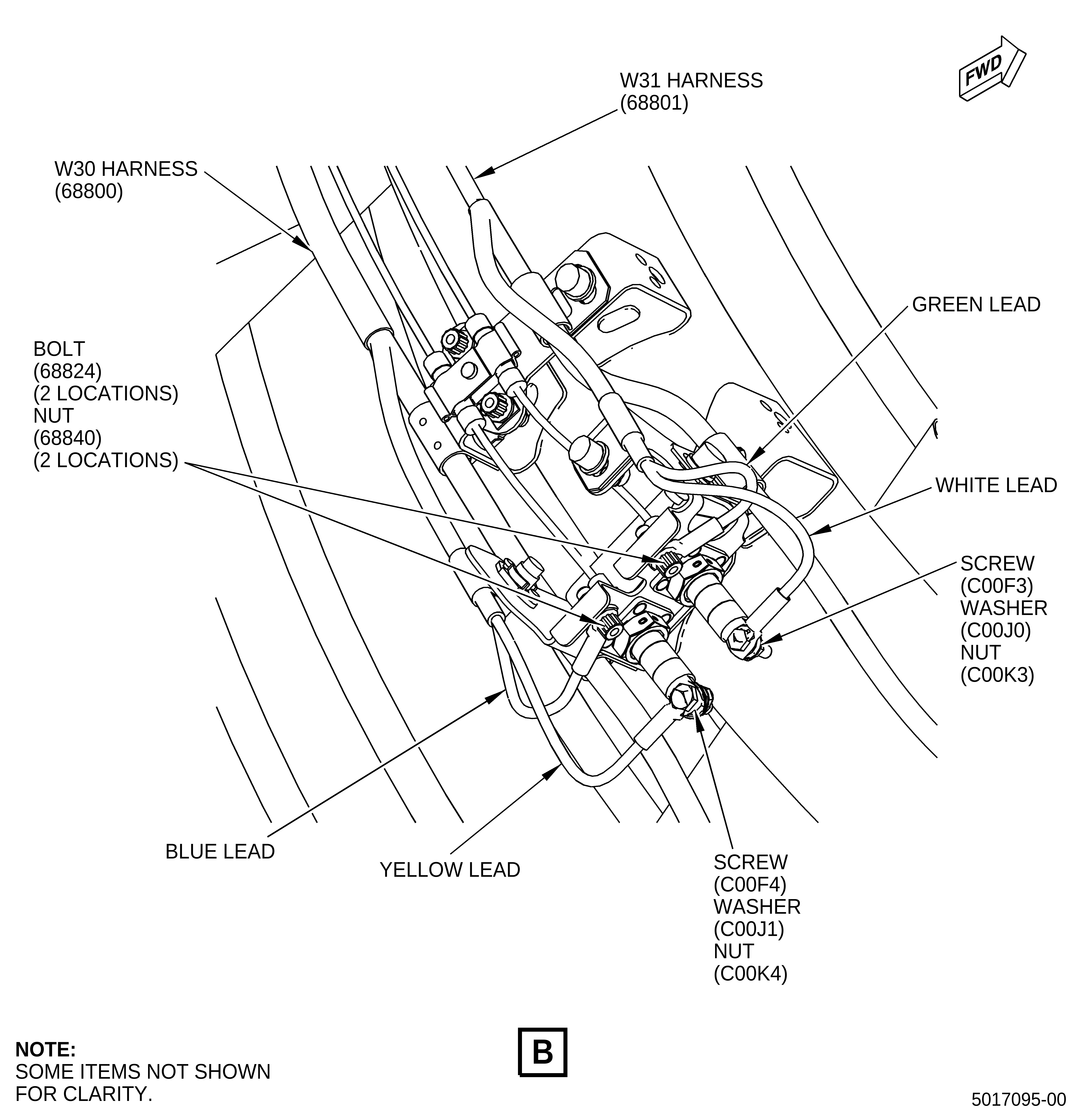
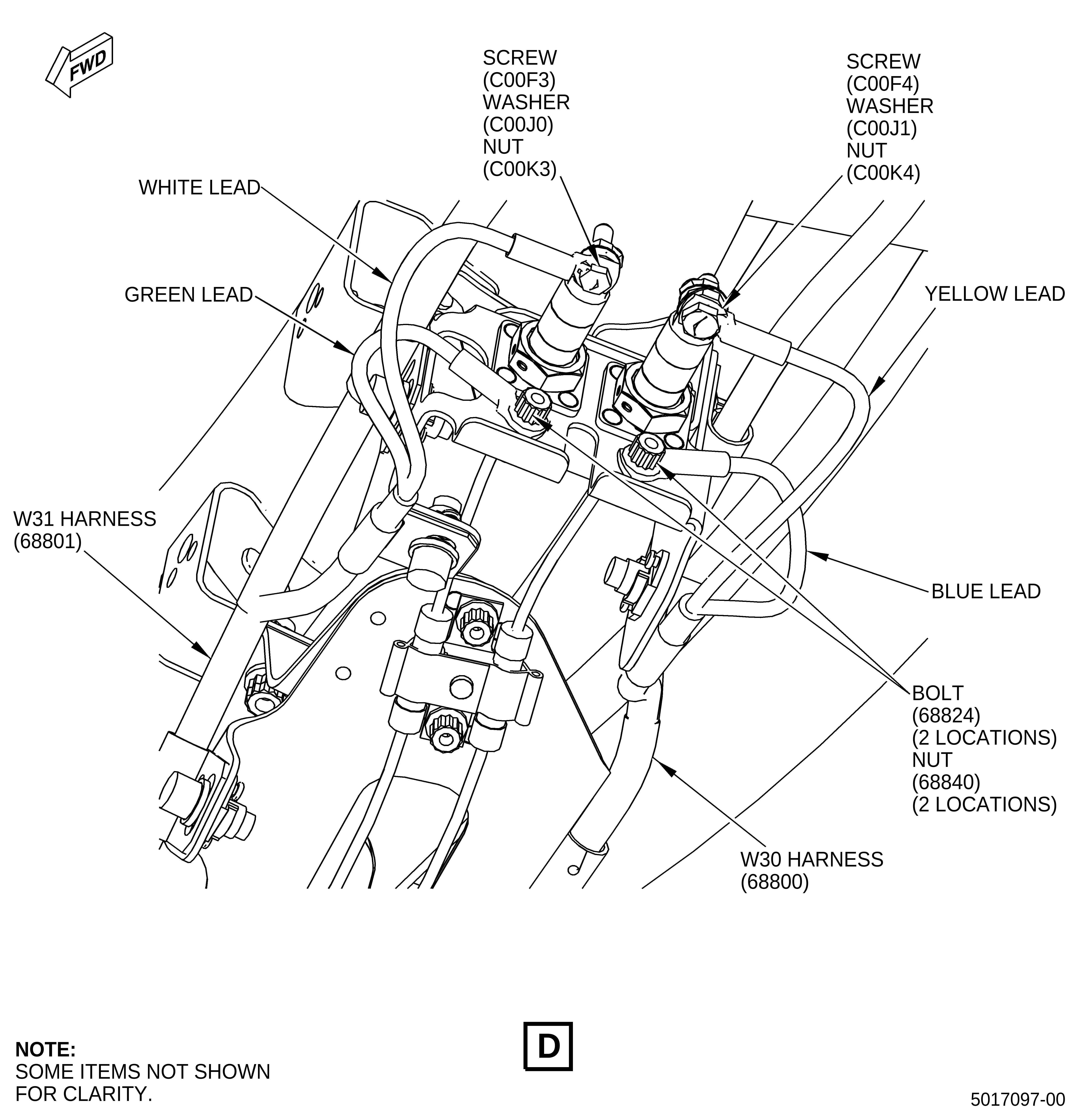
| (b) | Attach the sensing element terminals at the 4:15 o'clock position. Refer to Figure 6, Sheet 3, and do as follows: |
| 1 | Attach the W30 harness (SIN 68800) terminal ends on the L/H locations that follow: |
| a | Connect the blue lead to ground with one bolt (SIN 68824) and nut (SIN 68840). |
| (1) | Torque the nut (SIN 68840) to 55 lb in. (6.2 N.m). |
| b | Connect the yellow lead to the L/H sensing element with one screw (SIN C00F4), washer (SIN C00J1) (under nut), and nut (SIN C00K4). |
| (1) | Torque the nut (SIN C00K4) to 35 lb in. (4.0 N.m). |
| 2 | Attach the W31 harness (SIN 68801) terminal ends on the R/H locations that follow: |
| a | Connect the green lead to ground with one bolt (SIN 68824) and nut (SIN 68840). |
| (1) | Torque the nut (SIN 68840) to 55 lb in. (6.2 N.m). |
| b | Connect the white lead to the R/H sensing element with one screw (SIN C00F3), washer (SIN C00J0) (under nut), and nut (SIN C00K3). |
| (1) | Torque the nut (SIN C00K3) to 25 lb in. (2.8 N.m). |
| (c) | Attach the sensing element terminals at the 4:45 o'clock position. Refer to Figure 6, Sheet 4, and do as follows: |
| 1 | Attach the W30 harness (SIN 68800) terminal ends on the L/H locations that follow: |
| a | Connect the blue lead to ground with one bolt (SIN 68824) and nut (SIN 68840). |
| (1) | Torque the nut (SIN 68840) to 55 lb in. (6.2 N.m). |
| b | Connect the yellow lead to the L/H sensing element with one screw (SIN C00F3), washer (SIN C00J0) (under nut), and nut (SIN C00K3). |
| (1) | Torque the nut (SIN C00K3) to 25 lb in. (2.8 N.m). |
| 2 | Attach the W31 harness (SIN 68801) terminal ends on the R/H locations that follow: |
| a | Connect the green lead to ground with one bolt (SIN 68824) and nut (SIN 68840). |
| (1) | Torque the nut (SIN 68840) to 55 lb in. (6.2 N.m). |
| b | Connect the white lead to the R/H sensing element with one screw (SIN C00F4), washer (SIN C00J1) (under nut), and nut (SIN C00K4). |
| (1) | Torque the nut (SIN C00K4) to 35 lb in. (4.0 N.m). |
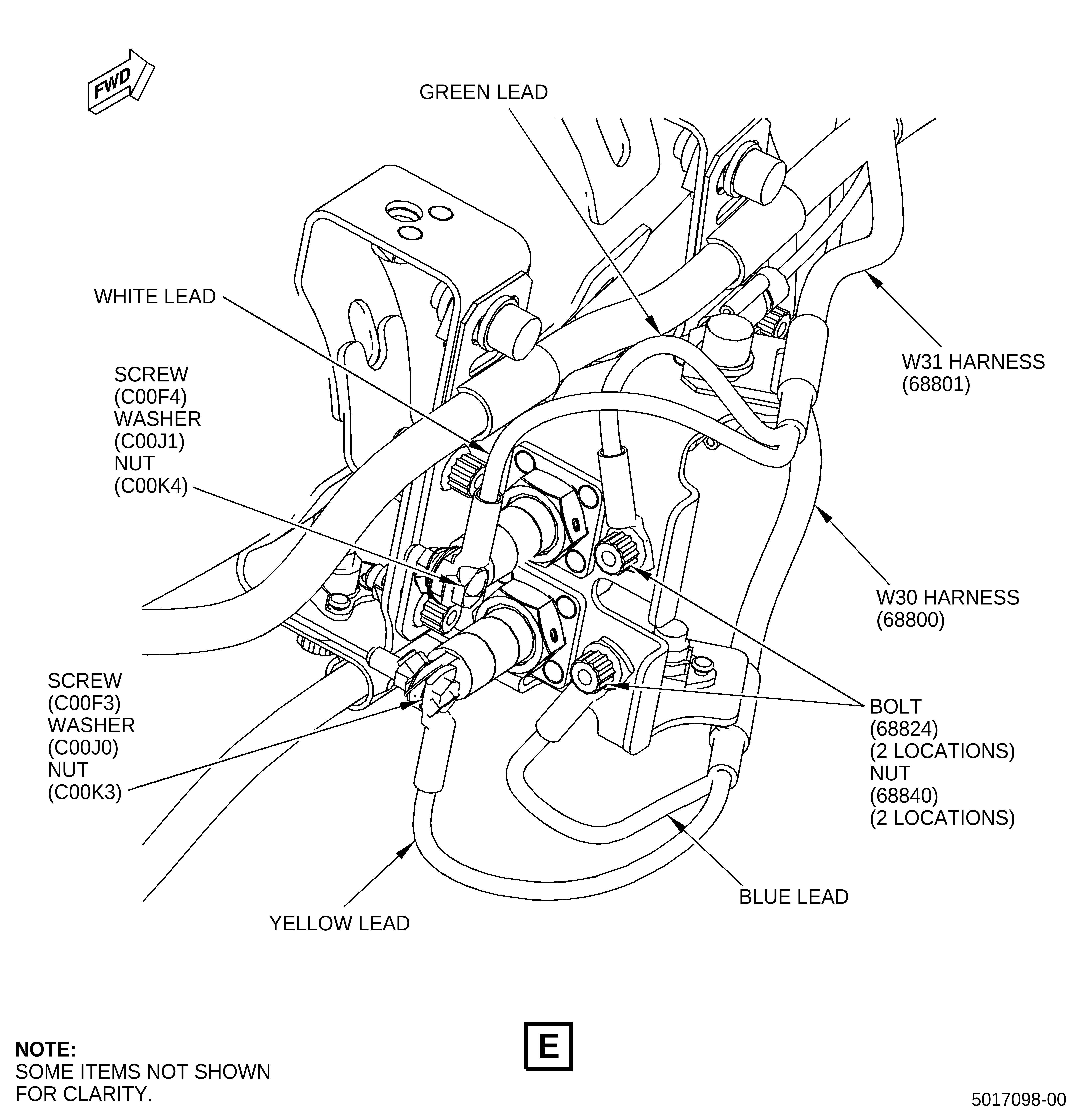
| (d) | Attach the sensing element terminals at the 7:15 o'clock position. Refer to Figure 6, Sheet 5, and do as follows: |
| 1 | Attach the W31 harness (SIN 68801) terminal ends on the forward locations that follow: |
| a | Connect the green lead to ground with one bolt (SIN 68824) and nut (SIN 68840). |
| (1) | Torque the nut (SIN 68840) to 55 lb in. (6.2 N.m). |
| b | Connect the white lead to the sensing element with one screw (SIN C00F3), washer (SIN C00J0) (under nut), and nut (SIN C00K3). |
| (1) | Torque the nut (SIN C00K3) to 25 lb in. (2.8 N.m). |
| 2 | Attach the W30 harness (SIN 68800) terminal ends on the aft locations that follow: |
| a | Connect the blue lead to ground with one bolt (SIN 68824) and nut (SIN 68840). |
| (1) | Torque the nut (SIN 68840) to 55 lb in. (6.2 N.m). |
| b | Connect the yellow lead to the sensing element with one screw (SIN C00F4), washer (SIN C00J1) (under nut), and nut (SIN C00K4). |
| (1) | Torque the nut (SIN C00K4) to 35 lb in. (4.0 N.m). |
| (e) | Attach the sensing element terminals at the 7:45 o'clock position. Refer to Figure 6, Sheet 6, and do as follows: |
| 1 | Attach the W31 harness (SIN 68801) terminal ends on the forward locations that follow: |
| a | Connect the green lead to ground with one bolt (SIN 68824) and nut (SIN 68840). |
| (1) | Torque the nut (SIN 68840) to 55 lb in. (6.2 N.m). |
| b | Connect the white lead to the forward sensing element with one screw (SIN C00F4), washer (SIN C00J1) (under nut), and nut (SIN C00K4). |
| (1) | Torque the nut (SIN C00K4) to 35 lb in. (4.0 N.m). |
| 2 | Attach the W30 harness (SIN 68800) terminal ends on the aft locations that follow: |
| a | Connect the blue lead to ground with one bolt (SIN 68824) and nut (SIN 68840). |
| (1) | Torque the nut (SIN 68840) to 55 lb in. (6.2 N.m). |
| b | Connect the yellow lead to the aft sensing element with one screw (SIN C00F3), washer (SIN C00J0) (under nut), and nut (SIN C00K3). |
| (1) | Torque the nut (SIN C00K3) to 25 lb in. (2.8 N.m). |
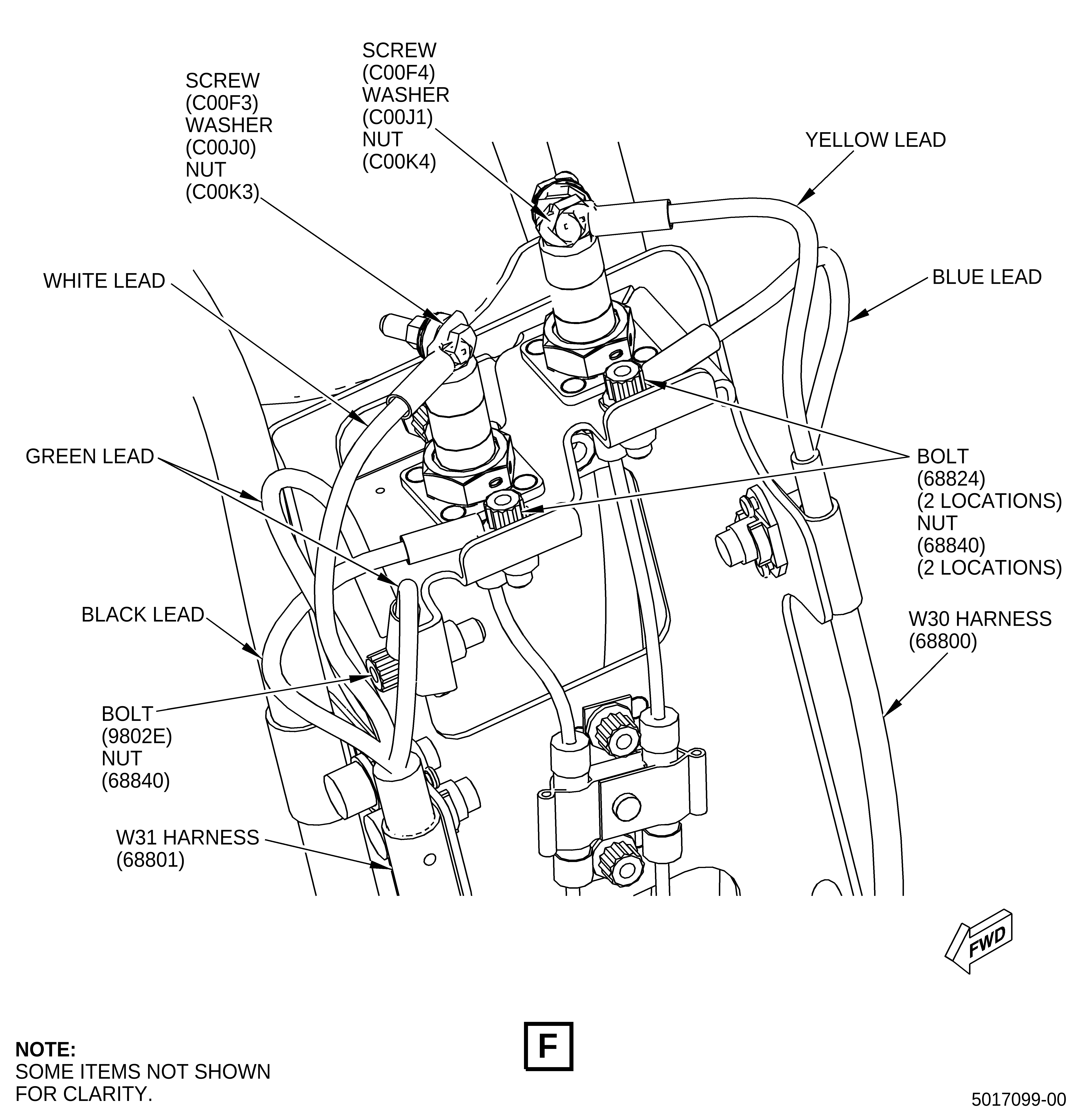
| (f) | Attach the sensing element terminals at the 10:15 o'clock position. Refer to Figure 6, Sheet 7, and do as follows: |
| 1 | Attach the W31 harness (SIN 68801) terminal ends on the forward locations that follow: |
| a | Connect the two green leads to ground with one bolt (SIN 9802E) and nut (SIN 68840) on the forward side of the bracket. |
| (1) | Torque the nut (SIN 68840) to 55 lb in. (6.2 N.m). |
| b | Connect the black lead to ground with one bolt (SIN 68824) and nut (SIN 68840). |
| (1) | Torque the nut (SIN 68840) to 55 lb in. (6.2 N.m). |
| c | Connect the white lead to the forward sensing element with one screw (SIN C00F3), washer (SIN C00J0) (under nut), and nut (SIN C00K3). |
| (1) | Torque the nut (SIN C00K3) to 25 lb in. (2.8 N.m). |
| 2 | Attach the W30 harness (SIN 68800) terminal ends on the aft locations that follow: |
| a | Connect the blue lead to ground with one bolt (SIN 68824) and nut (SIN 68840). |
| (1) | Torque the nut (SIN 68840) to 55 lb in. (6.2 N.m). |
| b | Connect the yellow lead to the aft sensing element with one screw (SIN C00F4), washer (SIN C00J1) (under nut), and nut (SIN C00K4). |
| (1) | Torque the nut (SIN C00K4) to 35 lb in. (4.0 N.m). |
| (5) | Torque the hardware that attach the W30 harness (SIN 68800) (blue-violet). Refer to Figure 3 and do as follows: |
| (a) | Make sure to start at the 12:00 o'clock position and continue CW. Do a visual inspection of the clamps to make sure they are centered and give a smooth contour to the harness. |
| 1 | Torque the three bolts (SIN 68823) that are between the 12:00 and 2:00 o'clock positions to 65 lb in. (7.3 N.m). Refer to Figure 3, Sheet 2. |
| 2 | Torque the bolt (SIN 98021) and six bolts (SIN 68823) that are between the 2:30 and 3:45 o'clock positions to 65 lb in. (7.3 N.m). Refer to Figure 3, Sheet 3. |
| 3 | Torque the two bolts (SIN 98021) and five bolts (SIN 68823) that are between the 4:15 and 5:45 o'clock positions to 65 lb in. (7.3 N.m). Refer to Figure 3, Sheet 4. |
| 4 | Torque the two bolts (SIN 98021) and seven bolts (SIN 68823) that are between the 6:00 and 8:00 o'clock positions to 65 lb in. (7.3 N.m). Refer to Figure 3, Sheet 5. |
| 5 | Torque the five bolts (SIN 68823) that are between the 8:45 and 10:00 o'clock positions to 65 lb in. (7.3 N.m). Refer to Figure 3, Sheet 6. |
| (6) | Torque the hardware that attaches the W31 harness (SIN 68801) (blue-orange). Refer to Figure 4 and do as follows: |
| (a) | Make sure to start at the 12:00 o'clock position and continue CCW. Do a visual inspection of the clamps to make sure they are centered and give a smooth contour to the harness. |
| 1 | Torque the four bolts (SIN 68823) that are between the 12:00 and 10:00 o'clock positions to 65 lb in. (7.3 N.m). Refer to Figure 4, Sheet 2. |
| 2 | Torque the four bolts (SIN 68823) that are between the 10:15 and 9:30 o'clock positions to 65 lb in. (7.3 N.m). Refer to Figure 4, Sheet 3. |
| 3 | Torque the three bolts (SIN 68823) that are between the 9:00 and 8:30 o'clock positions to 65 lb in. (7.3 N.m). Refer to Figure 4, Sheet 4. |
| 4 | Torque the nine bolts (SIN 68823) that are between the 8:00 and 6:30 o'clock positions to 65 lb in. (7.3 N.m). Refer to Figure 4, Sheet 5. |
| 5 | Torque the eight bolts (SIN 68823) that are between the 6:00 and 4:00 o'clock positions to 65 lb in. (7.3 N.m). Refer to Figure 4, Sheet 6. |
| 6 | Torque the five bolts (SIN 68823) that are between the 3:15 and 1:45 o'clock positions to 65 lb in. (7.3 N.m). Refer to Figure 4, Sheet 7. |