| GEnx-1B SERVICE BULLETIN - 73-0103 R00 | Revised: 09/12/2022 | |
| SB 73-0103 R00 ENGINE FUEL AND CONTROL - Fuel Injection Nozzles (73-11-30) - In-Shop Fuel Nozzle Machine Bolt Replacement with Safety Cable Installation | Issued: 09/12/2022 | |
| GEnx-1B SERVICE BULLETIN - 73-0103 R00 | Revised: 09/12/2022 | |
| SB 73-0103 R00 ENGINE FUEL AND CONTROL - Fuel Injection Nozzles (73-11-30) - In-Shop Fuel Nozzle Machine Bolt Replacement with Safety Cable Installation | Issued: 09/12/2022 | |
| GE Designated: -CONFIDENTIAL- | |
| The information contained in this document is GE proprietary information and is disclosed in confidence. It is the property of GE and shall not be used, disclosed to others or reproduced without the express written consent of GE, including, but without limitation, it is not to be used in the creation, manufacture, development, or derivation of any repairs, modifications, spare parts, designs, or configuration changes or to obtain FAA or any other government or regulatory approval to do so. If consent is given for reproduction in whole or in part, this notice and the notice set forth on each page of this document shall appear in any such reproduction in whole or part. | |
| This technical data is considered subject to the Export Administration Regulations (EAR) pursuant to 15 CFR Parts 730-774. Transfer of this data by any means to a Non-U.S. Person, whether in the United States or abroad, without the proper U.S. Government authorization (e.g., License, exemption, NLR, etc.), is strictly prohibited. | |
| Copyright (2022) General Electric Company, U.S.A. |
| 1. | PLANNING INFORMATION |
| A. | Effectivity |
| * * * FOR GEnx-1B64, -1B64/P1, -1B64/P2, -1B67, -1B67/P1, -1B67/P2, -1B70, -1B70/75/P1, -1B70/75/P2, -1B70/P1, -1B70/P2, -1B70C/P1, -1B70C/P2, -1B74/75/P1, -1B74/75/P2, -1B76/P2, -1B76A/P2 |
| This Service Bulletin is applicable to these GEnx-1B engines: |
| • |
|
| This Service Bulletin has been introduced in production to these GEnx-1B engines: |
| • |
|
| These serial numbers are the best available data. |
| The machine bolts P/N J1494P15A and P/N AS3237-16 are affected by this Service Bulletin. |
| B. | Description |
| This Service Bulletin provides instructions to replace all the affected machine bolts with new short machine bolts P/N J1494P13B or P/N AS3244-14 with safety cable kit (safety cable) or safety wire retention feature. |
| C. | Compliance |
| Category 3 |
| GE recommends that you do this Service Bulletin at the next shop visit of the engine/module. |
| Impact C |
| This recommendation is to address a condition that may result in a Non-Event operational disruption, Unscheduled Engine Removals (UER), Out-Station-Removals or Aircraft on the Ground (AOG). |
| Compliance with this Service Bulletin is the closing action for GEnx-1B S/B 73-0057 and/or GEnx-1B S/B 73-0059. |
| NOTE: |
|
| This Service Bulletin is offered to improve the reliability or performance of your GE product, or to help prevent the occurrence of the event or condition described in this Service Bulletin. If the operator elects not to participate in the bulletin, that decision will be taken into consideration by GE in evaluating future product performance issues that may arise in the operators fleet. |
| D. | Concurrent Requirements |
| None. |
| E. | Reason |
| (1) | Objective: |
| To introduce new parts and improve reliability. |
| (2) | Condition: |
| The machine bolt sizing issue is observed during fuel nozzle removal. In the worst scenario, a machine bolt breakage occurs, which causes an increase in maintenance time and high risk of combustor diffuser nozzle (CDN) case damage. |
| (3) | Cause: |
| The machine bolt/insert sizing issue is driven by the machine bolt tip oxidation accumulation and machine bolt thread deformation/damage by the fuel nozzle inserts crimped feature (occurred during installation and removal). The new short machine bolts will reduce the risk coming from oxidation. |
| (4) | Improvement: |
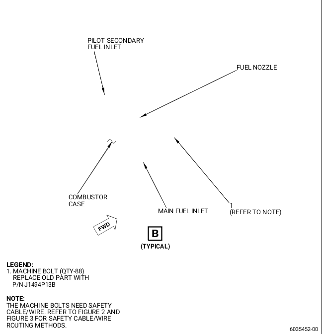
| The current fuel nozzle machine bolt is being replaced with a new short machine bolt at all 88 locations. This will reduce machine bolt tip protrusion from the insert, which reduces machine bolt tip oxidation. The new machine bolts will be secured with safety cable/wire to avoid machine bolt liberation recognized by GEnx-1B S/B 73-0057 and GEnx-1B S/B 73-0059. |
| This is also the first part of the effort related to the machine bolt/insert sizing containment plan, where short machine bolts with safety cable/wire release is a first step and later another Service Bulletin will release free running inserts, where short machine bolts with safety cable/wire will be an obligatory solution. |
| (5) | Substantiation: |
| Substantiation is by analysis, comparative analysis, and fleet experience. |
| F. | Approval |
| The data contained in this Service Bulletin has been reviewed by the FAA or authorized entity representing the FAA and the repair(s) and modification(s) herein comply with the applicable Aviation Regulations and are APPROVED for installation in the model(s) listed in this Service Bulletin. |
| G. | Manpower |
| After you replace all the machine bolts with new ones, the safety cable/wire installation process for the full set is taking 70 minutes for each engine. |
| H. | Weight and Balance |
| Weight and balance are not changed. |
| I. | References (Use the latest version of these documents) |
| GEK 9250, Commercial Engine Standard Practices Manual (SPM) |
| GEK 112851, GEnx-1B Engine Manual (EM) |
| GEK 112864, GEnx-1B Engine Illustrated Parts Catalog (EIPC) |
| GEnx-1B S/B 73-0057, ENGINE FUEL AND CONTROL - Fuel Injection Nozzles (73-11-30) - Fuel Nozzle Machine Bolt Replacement |
| GEnx-1B S/B 73-0059, ENGINE FUEL AND CONTROL - Fuel Injection Nozzles (73-11-30) - Fuel Nozzle Machine Bolt Replacement |
| NOTE: |
|
| J. | Publications Affected |
| GEK 112851, GEnx-1B Engine Manual (EM) |
| GEK 112864, GEnx-1B Engine Illustrated Parts Catalog (EIPC) |
| K. | Interchangeability |
| Qualified Interchangeability. |
| The new short machine bolts are one-way interchangeable with the old long type of the machine bolts. The new machine bolts are replaced with an as required amount of safety cable/wire secondary retention feature. The new short machine bolts require an obligatory safety cable/wire secondary retention feature installation (the new machine bolts have secondary retention feature holes in the bolthead). |
| L. | Software Accomplishment Summary |
| Not applicable. |
| 2. | MATERIAL INFORMATION |
| A. | Material - Price and Availability |
| (1) | Parts necessary to do this Service Bulletin: |
|
| *Part not supplied by GE Engine Services Distribution L.L.C. Procure through local purchase. |
| NP = Not Provisioned |
| NOTE: |
|
| (2) | Other Spare Parts: |
| None. |
| (3) | Consumables: |
|
| B. | Industry Support Information |
| None. |
| C. | Configuration Chart |
|
||||||||||||||||||||||||||||||||||||||||||||||||||||||||||||||||||||||||||||||||||||||||||||||||||||||||||||||||||||||||||||||||||||||||||||||||||||||||||||||||||||||||||||||||||||||||||||||||||||||||||||||||||||||||||||||||||||||||||||||||||||||||||||||||||||||||||||||||||||||||||||||||||||||||||||||||||||||||||||||||||||||||||||||||||||||||||||||||||||||||||||||||||||||||||||||||||||||||||||||||||||||||||||||||||||||||||||||||||||||||||||||||||||||||||||||||||||||||||||||||
| Operation Codes AD=Add RE=Replace RM=Remains RW=Rework |
| Change Codes 5=Qualified interchangeability. Refer to paragraph 1.K., Interchangeability. |
| Support Codes A=Old parts will no longer be supplied. E=Old parts will be supplied, and can be used at other engine locations. |
| D. | Parts Disposition |
| Discard old parts. |
| E. | Tooling - Price and Availability |
| None. |
| 3. | ACCOMPLISHMENT INSTRUCTIONS |
| A. | General |
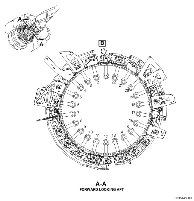
| (1) | Remove the fuel nozzles (Figure 1). Removal instructions for the fuel nozzles have not changed. Refer to the GEnx-1B EM, 72-41-00, DISASSEMBLY 001, CONFIG 01, Subtask 72-41-00-040-024 or CONFIG 02, Subtask 72-41-00-040-044 and do as follows: |
| (a) | Discard the old machine bolts (1, Figure 1) and the seal assemblies (C-seals) under the fuel nozzles. |
| (2) | Install the fuel nozzles with the new machine bolts (1, Figure 1) and new C-seals. Installation instructions for the fuel nozzles have changed. Refer to the GEnx-1B EM, 72-40-00, ASSEMBLY 001, CONFIG 01, Subtask 72-40-00-440-085 or CONFIG 02, Subtask 72-40-00-440-180 and do as follows: |
| CAUTION: |
|
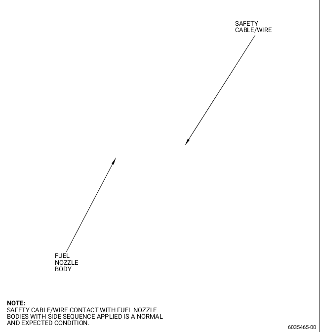
| (a) | Safety the new machine bolts (1, Figure 1) with C10-143 safety cable or C10-071 safety wire. Refer to the SPM, 70-11-01, SAFETY WIRE PROCEDURE, for safety wire installation, 70-11-02, SAFETY CABLE PROCEDURE, for safety cable installation, Figure 2 and Figure 3 of this Service Bulletin, and do as follows: |
| 1 | Pair two neighbor machine bolts (1, Figure 1) next to each other with the sequence that follows: |
| a | Standard routing of C10-143 safety cable or C10-071 safety wire is forward-aft sequence. Refer to Figure 2. |
| b | For locations where standard forward-aft routing is not possible, continue with side sequence. Refer to Figure 3. |
| NOTE: |
|
| NOTE: |
|
| 2 | Do an inspection of all safety cables/wires on the new machine bolts (1, Figure 1) to make sure that none are neutral or pulling loose. |