| GEnx-1B SERVICE BULLETIN - 74-0004 R00 | Revised: 03/10/2015 | |
| SB 74-0004 R00 IGNITION - Ignition Exciters (74-11-10) - Introduction of New Exciter Box Base Support Bracket with New Nut Plate | Issued: 03/10/2015 | |
| GEnx-1B SERVICE BULLETIN - 74-0004 R00 | Revised: 03/10/2015 | |
| SB 74-0004 R00 IGNITION - Ignition Exciters (74-11-10) - Introduction of New Exciter Box Base Support Bracket with New Nut Plate | Issued: 03/10/2015 | |
| GE PROPRIETARY INFORMATION | |
| The information contained in this document is GE proprietary information and is disclosed in confidence. It is the property of GE and shall not be used, disclosed to others or reproduced without the express written consent of GE, including, but without limitation, it is not to be used in the creation, manufacture, development, or derivation of any repairs, modifications, spare parts, designs, or configuration changes or to obtain FAA or any other government or regulatory approval to do so. If consent is given for reproduction in whole or in part, this notice and the notice set forth on each page of this document shall appear in any such reproduction in whole or in part. | |
| This technical data is considered EAR controlled pursuant to 15 CFR Parts 730-774 respectively. Transfer of this data by any means to a Non-US Person, whether in the United States or abroad, without the proper U.S. Government authorization (e.g., License, exemption, NLR, etc.), is strictly prohibited. | |
| Copyright (2015) General Electric Company, U.S.A. |
| 1. | PLANNING INFORMATION |
| A. | Effectivity |
| * * * FOR GEnx-1B54, -1B54/P1, -1B54/P2, -1B58, -1B58/P1, -1B58/P2, -1B64, -1B64/P1, -1B64/P2, -1B67, -1B67/P1, -1B67/P2, -1B70, -1B70/72/P1, -1B70/72/P2, -1B70/75/P1, -1B70/75/P2, -1B70/P1, -1B70/P2, -1B74/75/P1, -1B74/75/P2, -1B75/P1, -1B75/P2, -1B78/P2 |
| This Service Bulletin is applicable to all GEnx-1B engines. |
| This Service Bulletin has been introduced in production to these GEnx-1B engines: |
| • |
|
| These serial numbers are the best available data. |
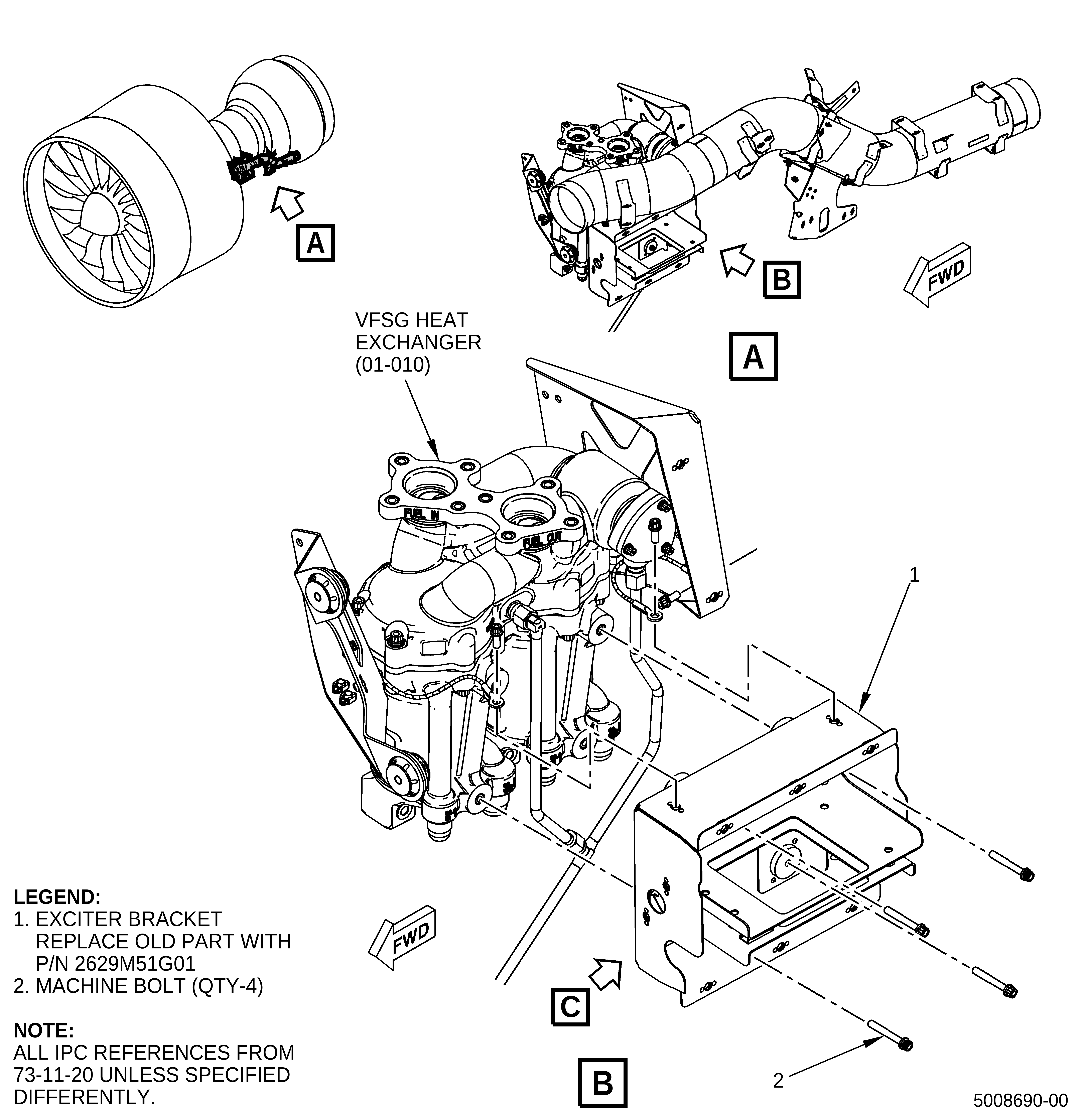
| The exciter box base support bracket (exciter bracket) P/N 2586M20G01 is affected by this Service Bulletin. |
| B. | Description |
| This Service Bulletin releases the new exciter bracket P/N 2629M51G01, deletes two self-locking nuts (nuts) P/N J1092P04 and two washers P/N NAS1149C0432R, and replaces two machine bolts P/N AS3237-08 with P/N AS3237-06. |
| C. | Compliance |
| Category 7 |
| GE recommends that you do this Service Bulletin at customer's convenience/option. |
| NOTE: |
|
| D. | Concurrent Requirements |
| GEnx-1B S/B 74-0003. |
| E. | Reason |
| (1) | Objective: |
| To introduce new parts and improve maintainability. |
| (2) | Condition: |
| The current design has loose washers and nuts that can be troublesome to assemble due to the tight clearances inside the exciter bracket. |
| (3) | Cause: |
| The nut plates were not part of the configuration introduced in GEnx-1B S/B 74-0003. |
| (4) | Improvement: |
| The new exciter bracket contains captive nut plates, which delete the loose hardware and allow for an easier assembly. |
| (5) | Substantiation: |
| Substantiation is by comparative analysis. |
| F. | Approval |
| The data contained in this Service Bulletin has been reviewed by the appropriate governmental authority and the repair(s) and modification(s) herein comply with the applicable Aviation Regulations and are APPROVED for installation in the model(s) listed in this Service Bulletin. |
| G. | Manpower |
| No additional man-hours are required to comply with this Service Bulletin. |
| H. | Weight and Balance |
| Weight and balance are not changed. |
| I. | References (Use the latest version of these documents) |
| GEK 112851, GEnx-1B Engine Manual (EM) |
| GEK 112864, GEnx-1B Engine Illustrated Parts Catalog (EIPC) |
| GEnx-1B S/B 74-0003, IGNITION - Ignition Exciters (74-11-10) - Release of Exciter Box Base with New Isolators |
| GEnx-1B Boeing 787 Aircraft Maintenance Manual (AMM) |
| NOTE: |
|
| J. | Publications Affected |
| GEK 112851, GEnx-1B Engine Manual (EM) |
| GEK 112864, GEnx-1B Engine Illustrated Parts Catalog (EIPC) |
| K. | Interchangeability |
| Qualified interchangeability. The proposed and superseded configurations must be introduced in complete engine sets. Mixing details of the proposed and superseded configuration on the same engine is not permitted. |
| L. | Software Accomplishment Summary |
| Not applicable. |
| 2. | MATERIAL INFORMATION |
| A. | Material - Price and Availability |
| (1) | Parts necessary to do this Service Bulletin: |
|
| *Part not supplied by GE Engine Services Distribution L.L.C. Procure through local purchase. |
| NP = Not Provisioned |
| NOTE: |
|
| (2) | Other Spare Parts: |
| None. |
| (3) | Consumables: |
| None. |
| B. | Industry Support Information |
| None. |
| C. | Configuration Chart |
|
| Operation Codes DE=Delete RE=Replace RM=Remains |
| Change Code 5=Qualified interchangeability. Refer to paragraph 1.K., Interchangeability. |
| Support Codes B=Old parts will be supplied until all old parts are sold. E=Old parts will be supplied, and can be used at other engine locations. |
| D. | Parts Disposition |
| The superseded machine bolts (P/N AS3237-08), deleted washers (P/N NAS1149C0432R), and nuts (P/N J1092P04) will be supplied and can be used in other engine locations. |
| Use the exciter brackets as specified in paragraph 1.K., Interchangeability until the supply is exhausted. If additional exciter brackets exist, they may be used as spares until the inventory is depleted. In any case, the exciter bracket, nut, washer, and machine bolt changes must be used together as a set as defined in paragraph 1.K., Interchangeability. |
| E. | Tooling - Price and Availability |
| None. |
| 3. | ACCOMPLISHMENT INSTRUCTIONS |
| A. | Replacement - On Wing |
| (1) | Refer to the GEnx-1B Boeing 787 AMM, DMC-B787-A-G73-22-01-00A-520A-A, for removal and DMC-B787-A-G73-22-01-00A-720A-A, for installation. |
| B. | Removal - In Shop |
| (1) | Remove the ignition cooling system. Refer to the GEnx-1B EM, 72-00-02, DISASSEMBLY 002, CONFIG 01, Subtask 72-00-02-030-401 or CONFIG 02, Subtask 72-00-02-030-560. |
| NOTE: |
|
| (2) | Remove the exciter bracket cover (01-010, 74-11-10) and disconnect the ignition leads from the igniters and ignition exciters. Refer to the GEnx-1B EM, 72-00-02, DISASSEMBLY 002, CONFIG 01, Subtask 72-00-02-030-402 or CONFIG 02, Subtask 72-00-02-030-576. |
| (3) | Disconnect the W9 and W10 harnesses from the ignition exciters. Refer to the GEnx-1B EM, 72-00-00, DISASSEMBLY 001, Subtask 72-00-00-030-230 and Subtask 72-00-00-030-231. |
| (4) | Remove the ignition exciters and the old exciter bracket (1, Figure 1). Refer to the GEnx-1B EM, 72-00-02, DISASSEMBLY 002, CONFIG 01, Subtask 72-00-02-030-402 or CONFIG 02, Subtask 72-00-02-030-576. |
| C. | Installation - In Shop |
| (1) | Install the ignition exciters and the new exciter bracket (1, Figure 1) with machine bolts (2, Figure 1). Refer to the GEnx-1B EM, 72-00-02, ASSEMBLY 005, CONFIG 01, Subtask 72-00-02-440-157 or CONFIG 02, Subtask 72-00-02-440-332. |
| (2) | Connect back the W9 and W10 harnesses. Refer to the GEnx-1B EM, 72-00-00, ASSEMBLY 001, Subtask 72-00-00-440-012 and Subtask 72-00-00-440-011. |
| (3) | Install the exciter bracket cover (01-010, 74-11-10) and connect the ignition leads to the igniters and the exciter boxes. Refer to the GEnx-1B EM, 72-00-02, ASSEMBLY 005, CONFIG 01, Subtask 72-00-02-440-157 or CONFIG 02, Subtask 72-00-02-440-332. |
| (4) | Install and connect back the ignition cooling system. Refer to the GEnx-1B EM, 72-00-02, ASSEMBLY 005, CONFIG 01, Subtask 72-00-02-440-164 or CONFIG 02, Subtask 72-00-02-440-367 and as follows: |
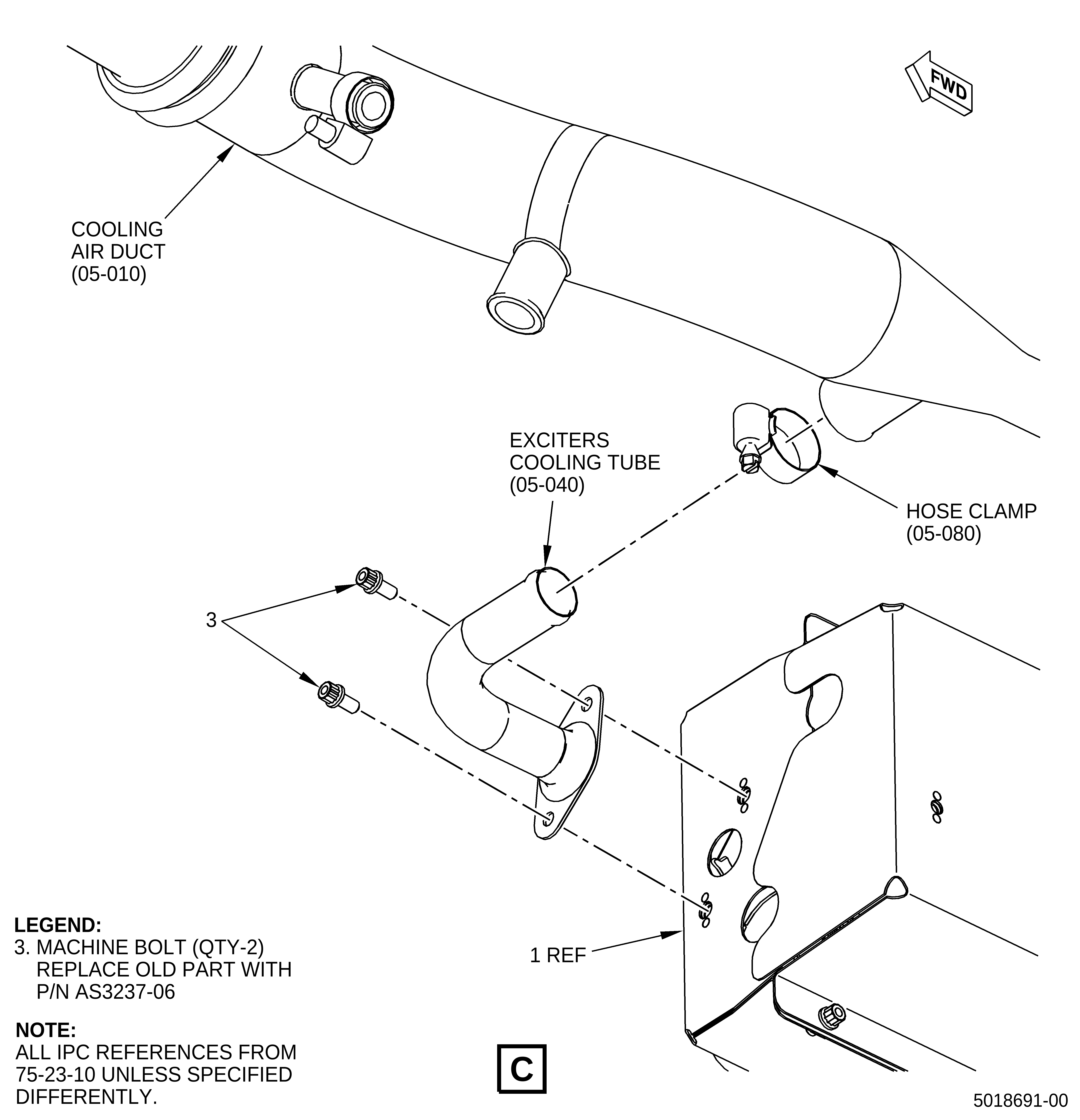
| (a) | Make sure that the exciters cooling tube (05-040, 75-23-10) is installed on the new exciter bracket (1, Figure 1) with two new machine bolts (3, Figure 1). |