| GEnx-1B SERVICE BULLETIN - 75-0003 R02 | Revised: 02/26/2013 | |
| SB 75-0003 R02 AIR SYSTEM - HPTACC Manifolds (75-24-30) - HPTACC Improvement | Issued: 08/20/2012 | |
| GEnx-1B SERVICE BULLETIN - 75-0003 R02 | Revised: 02/26/2013 | |
| SB 75-0003 R02 AIR SYSTEM - HPTACC Manifolds (75-24-30) - HPTACC Improvement | Issued: 08/20/2012 | |
| TRANSMITTAL INFORMATION |
| REVISION 2 TO SERVICE BULLETIN 75-0003 |
| Revision 2 is issued to update paragraph 1., PLANNING INFORMATION, and paragraph 2., MATERIAL INFORMATION. |
| Revision 1 was issued January 16, 2013. The original was issued on the August 20, 2012. Revision bars in the left margin identify changes. |
| 1. | PLANNING INFORMATION |
| A. | Effectivity |
|
| This Service Bulletin has been introduced in production to these GEnx-1B engines: |
| • |
|
| These serial numbers are the best available data. |
| The high pressure turbine active clearance control (HPTACC) manifold and the related hardware are affected by this Service Bulletin. |
| B. | Description |
| This Service Bulletin introduces the HPTACC manifold and support system to reduce wear and improve repairability. |
| C. | Compliance |
| Category 7 |
| GE recommends that you do this Service Bulletin at customer's convenience or option. |
| NOTE: |
|
| D. | Concurrent Requirements |
| None. |
| E. | Reason |
| (1) | Objective: |
| To introduce new parts, improve maintainability, and improve durability. |
| (2) | Condition: |
| The current six unique panel part numbers design has resulted in wear and reduced HPTACC system durability. |
| (3) | Cause: |
| The pinned connections at six locations on the panel allow vibration, displacement, and wear. Spray on wear pad is not repairable. |
| (4) | Improvement: |
| The wear pad replacement can be performed without replacing the entire panel due to the part count reduction from 11 to four released by this new HPTACC system design. |
| The released design has a spring dampener mounting system that allows the panels to absorb thermal displacement, but restrains the panel against vibration displacements. |
| (5) | Substantiation: |
| Substantiation is by analysis. |
| F. | Approval |
| This Service Bulletin has been reviewed by the FAA and the repair(s) and modification(s) herein comply with the applicable Federal Aviation Regulations and are FAA APPROVED for installation in the model(s) listed in this Service Bulletin. |
| G. | Manpower |
| After you get access to the propulsor module assembly or HPTACC manifold, you will need approximately 6.0 man-hours to do the replacement portion of this Service Bulletin. |
| H. | Weight and Balance |
| The complete compliance with this Service Bulletin increases weight by 0.45 lb (0.20 kg). |
| I. | References (Use the latest version of these documents) |
| GEK 112851, GEnx-1B Engine Manual (EM) |
| GEK 112864, GEnx-1B Engine Illustrated Parts Catalog (EIPC) |
| NOTE: |
|
| J. | Publications Affected |
| GEK 112851, GEnx-1B Engine Manual (EM) |
| GEK 112864, GEnx-1B Engine Illustrated Parts Catalog (EIPC) |
| K. | Interchangeability |
| The proposed and superseded hardware must be introduced as complete engine sets. Mixing the details of proposed and superseded hardware on the same engine is not permitted. |
| L. | Software Accomplishment Summary |
| Not applicable. |
| 2. | MATERIAL INFORMATION |
| A. | Material - Price and Availability |
| (1) | Parts necessary to do this Service Bulletin: |
|
| * Part not supplied by GE Engine Services Distribution L.L.C. Procure through local purchase. |
| NP: Not Provisioned |
| NOTE: |
|
| (2) | Other Spare Parts: |
| None. |
| (3) | Consumables: |
|
| B. | Industry Support Information |
| None. |
| C. | Configuration Chart |
|
| Operation Codes AD=Add DE=Delete RE=Replace RM=Remains QTC=Quantity Change |
| Change Code 5=Qualified interchangeability. Refer to paragraph 1.K., Interchangeability. |
| Support Codes B=Old parts will be supplied until all old parts are sold. E=Old parts will be supplied, and can be used at other engine locations. |
| D. | Parts Disposition |
| Use serviceable old parts for engines that have not changed. |
| E. | Tooling - Price and Availability |
| None. |
| 3. | ACCOMPLISHMENT INSTRUCTIONS |
| A. | Removal. |
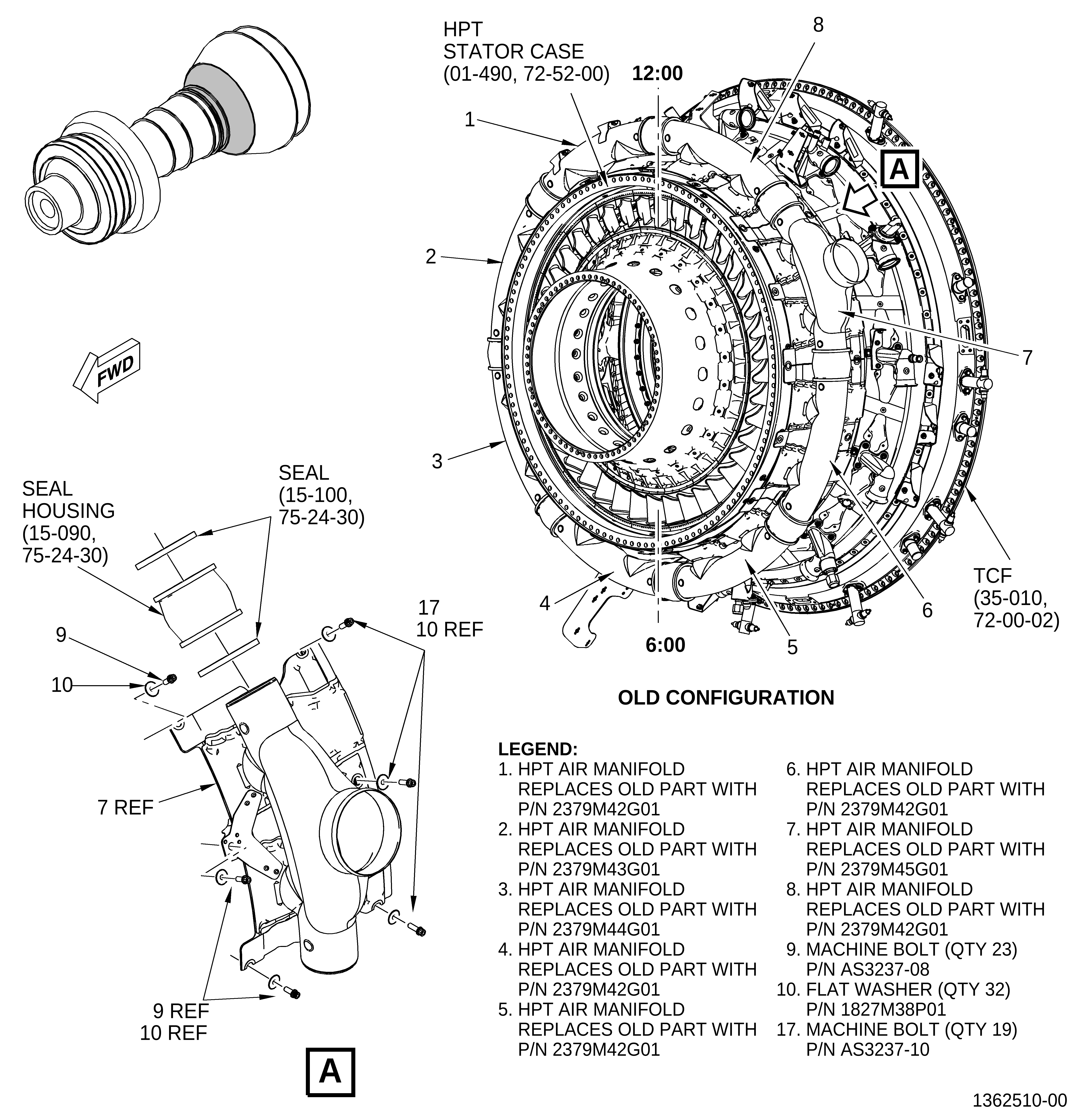
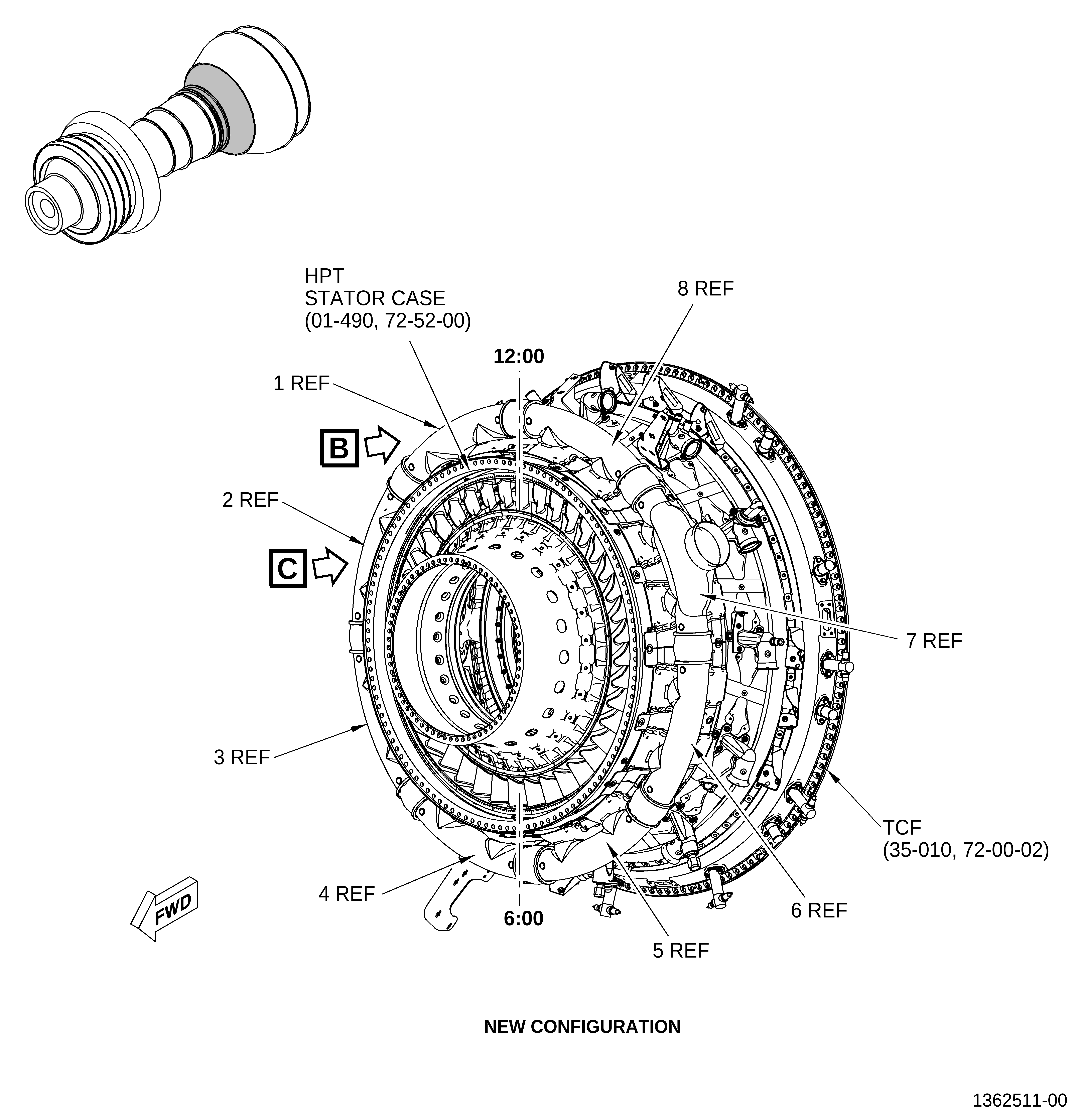
| (1) | Removal instructions of the HPTACC manifolds (1, 2, 3, 4, 5, 6, 7, 8, Figure 1) have not changed. Refer to the GEnx-1B EM, 72-00-02, DISASSEMBLY 003, Subtask 72-00-02-030-441. |
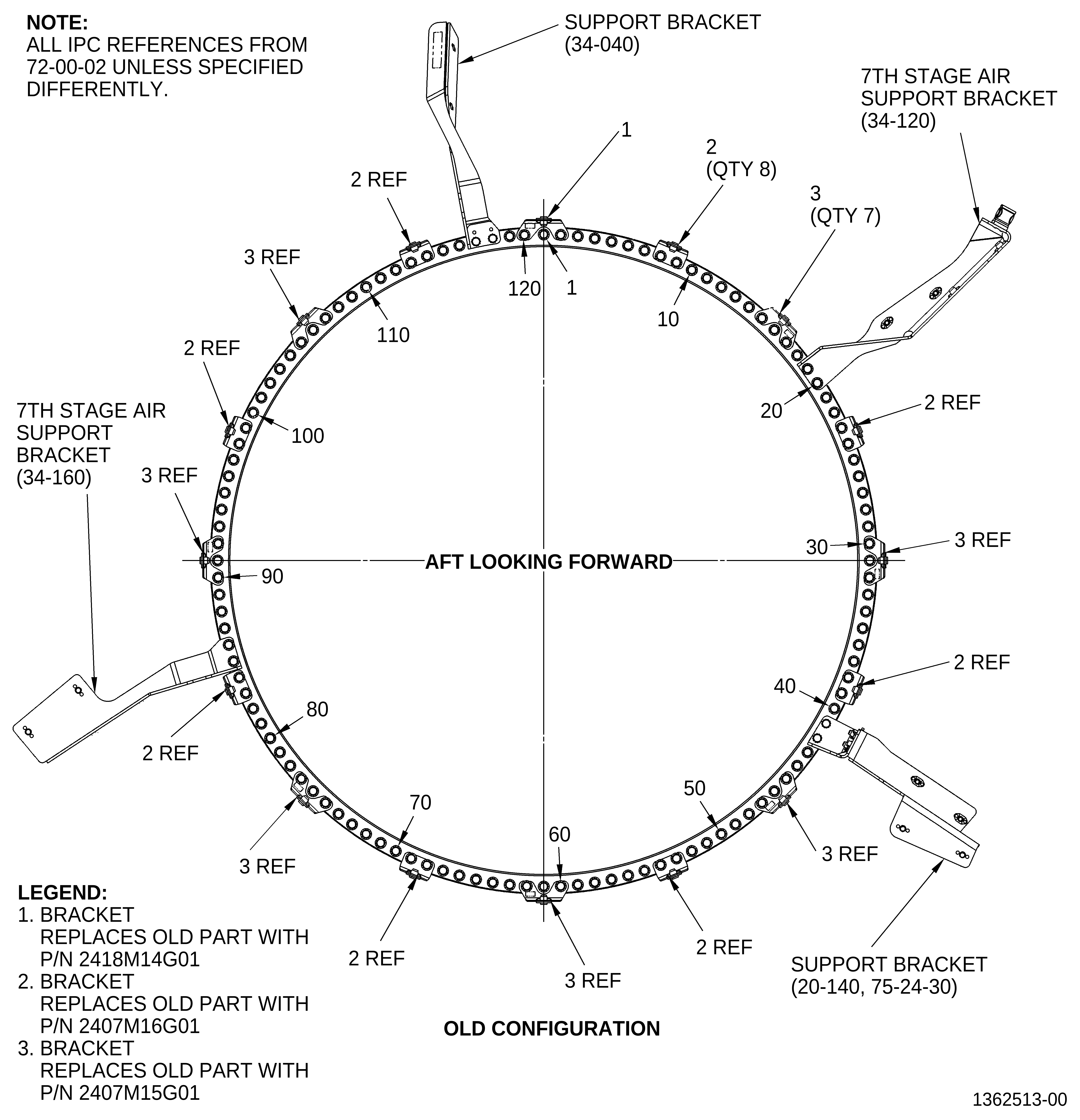
| (2) | Removal instructions of the support bracket (1, Figure 2) and brackets (2, Figure 2) have not changed. Refer to the GEnx-1B EM, 72-50-00, DISASSEMBLY 001, Subtask 72-50-00-030-033. |
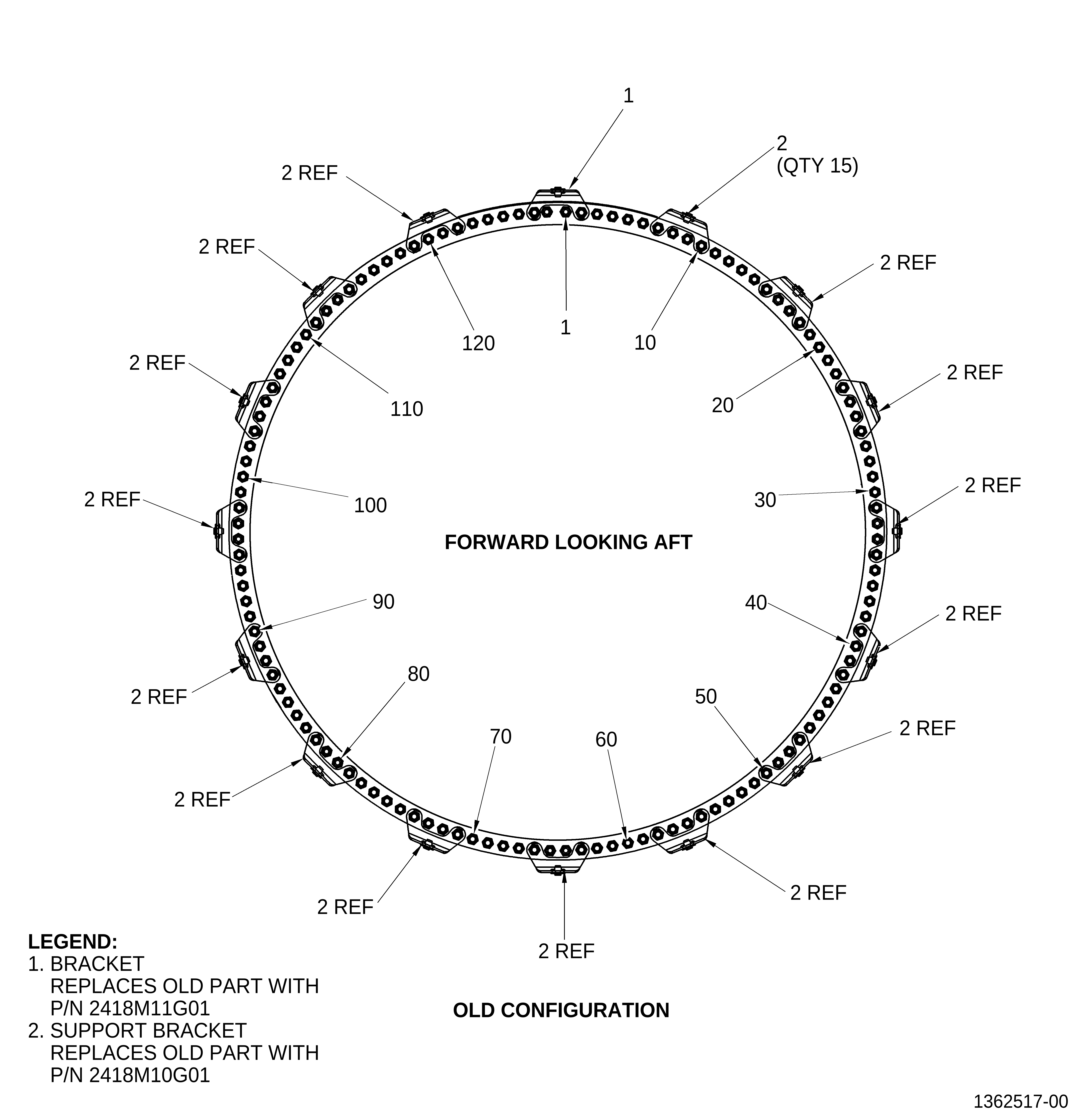
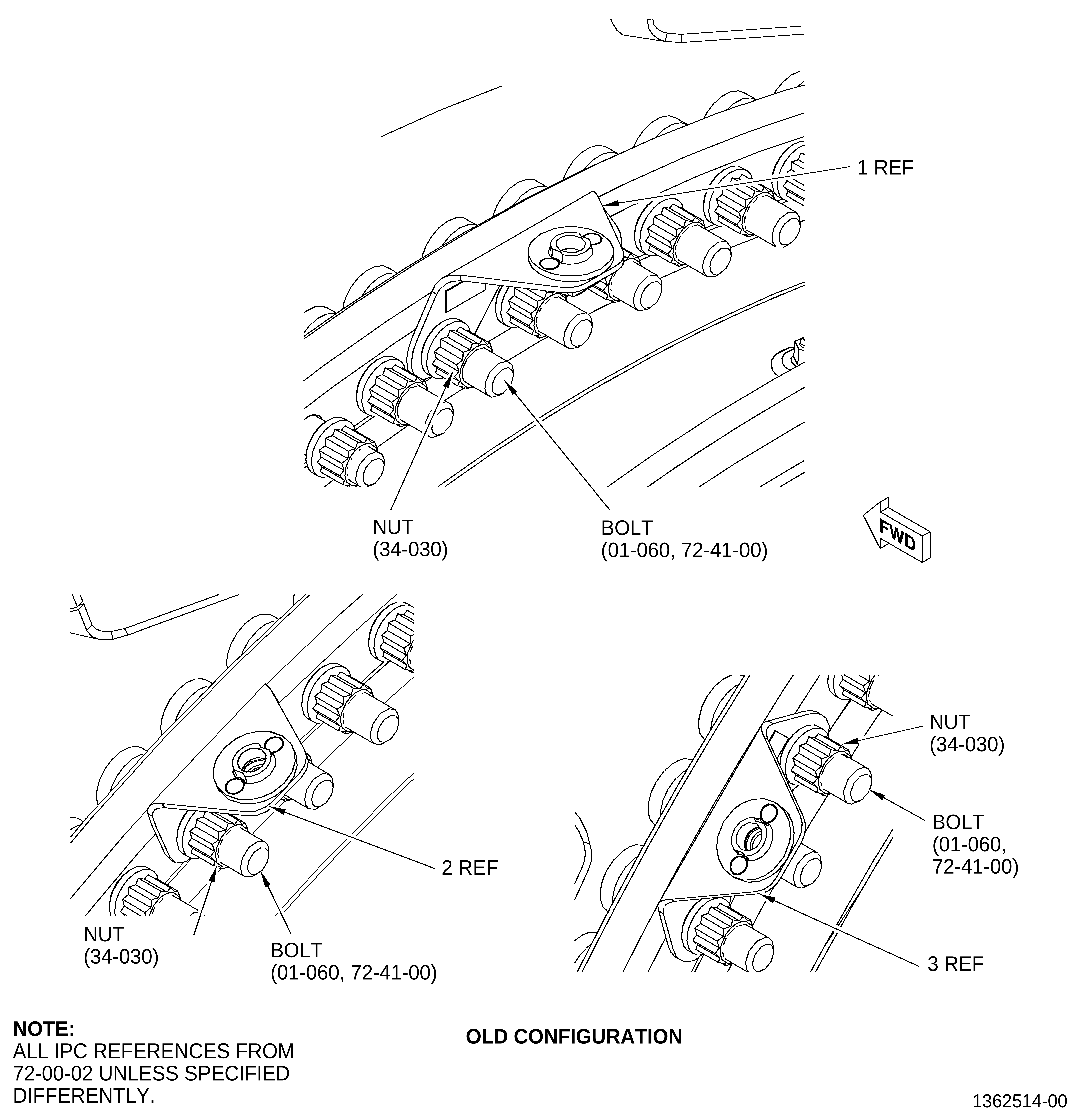
| (3) | Removal instructions of the bracket (1, Figure 3), brackets (2, Figure 3), and brackets (3, Figure 3) have not changed. Refer to the GEnx-1B EM, 72-50-00, DISASSEMBLY 001, Subtask 72-50-00-030-050. |
| B. | Installation. |
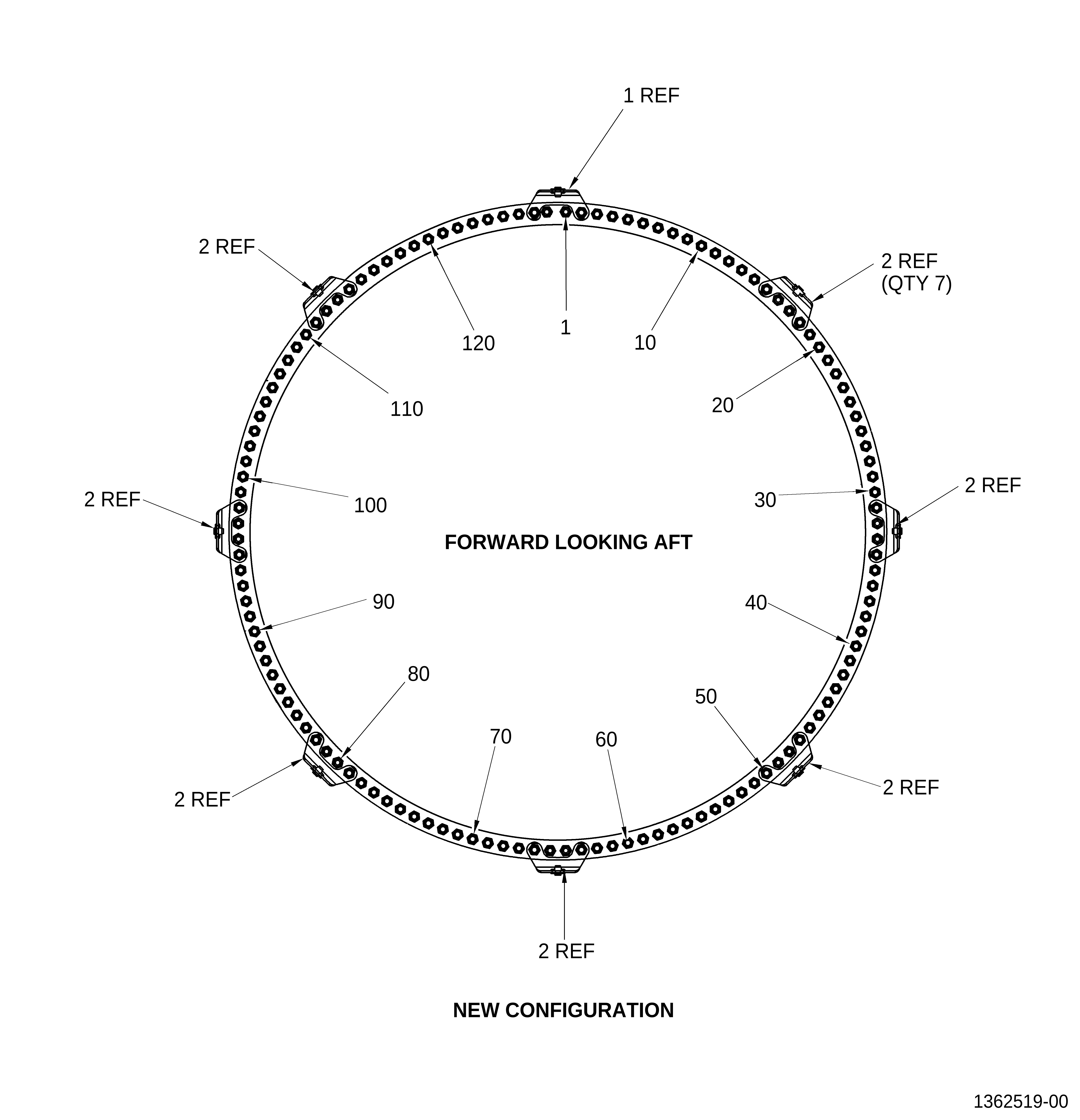
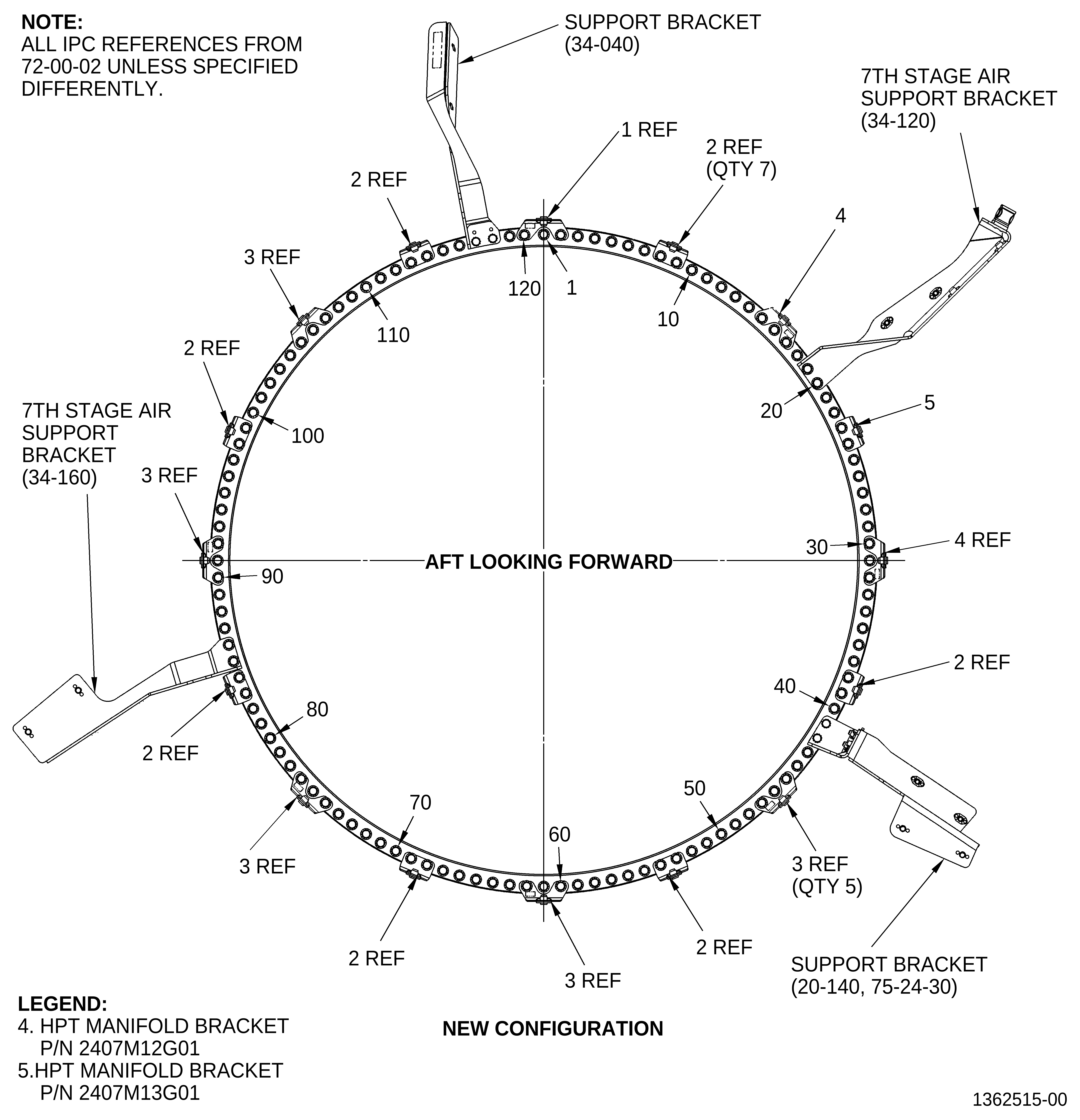
| (1) | Install the brackets (1, 2, 3, 4, and 5, Figure 1) on the HPT stage 2 nozzle assembly as follows: |
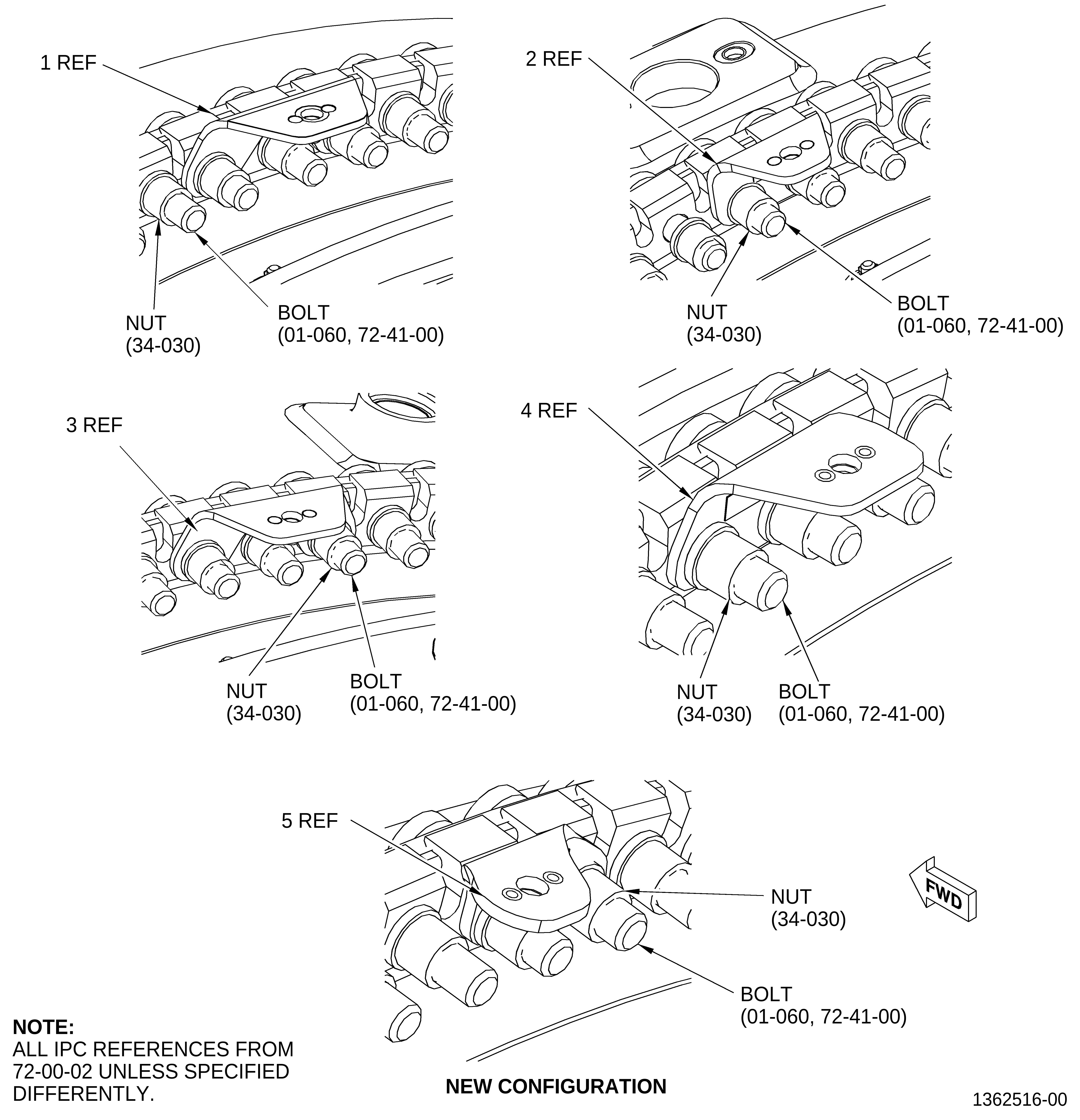
| (a) | Install the bracket (1, Figure 3, Sheet 4) at boltholes No. 2 and No. 120 with the nuts (34-030, 72-00-02). Hand tighten the nuts (34-030). |
| (b) | Install the bracket (2, Figure 3, Sheet 4) at boltholes No. 8-9, 38-39, 53-54, 68-69, 83-84, 98-99, and 113-114 with the nuts (34-030). Hand tighten the nuts (34-030). |
| (c) | Install the bracket (3, Figure 3, Sheet 4) at boltholes No. 45-47, 60-62, 75-77, 90-92, and 105-107 with the nuts (34-030). Hand tighten the nuts (34-030). |
| (d) | Install the HPT manifold brackets (4, Figure 3, Sheet 4) at boltholes No. 15-16 and 30-31 with the nuts (34-030). Hand tighten the nuts (34-030). |
| (e) | Install the HPT manifold bracket (5, Figure 3, Sheet 4) at boltholes No. 24-25 with the nuts (34-030). Hand tighten the nuts (34-030). |
| (f) | Torque all the 32 nuts (34-030) in a criss-cross pattern to 368-432 lb in. (41.6-48.8 N.m). |
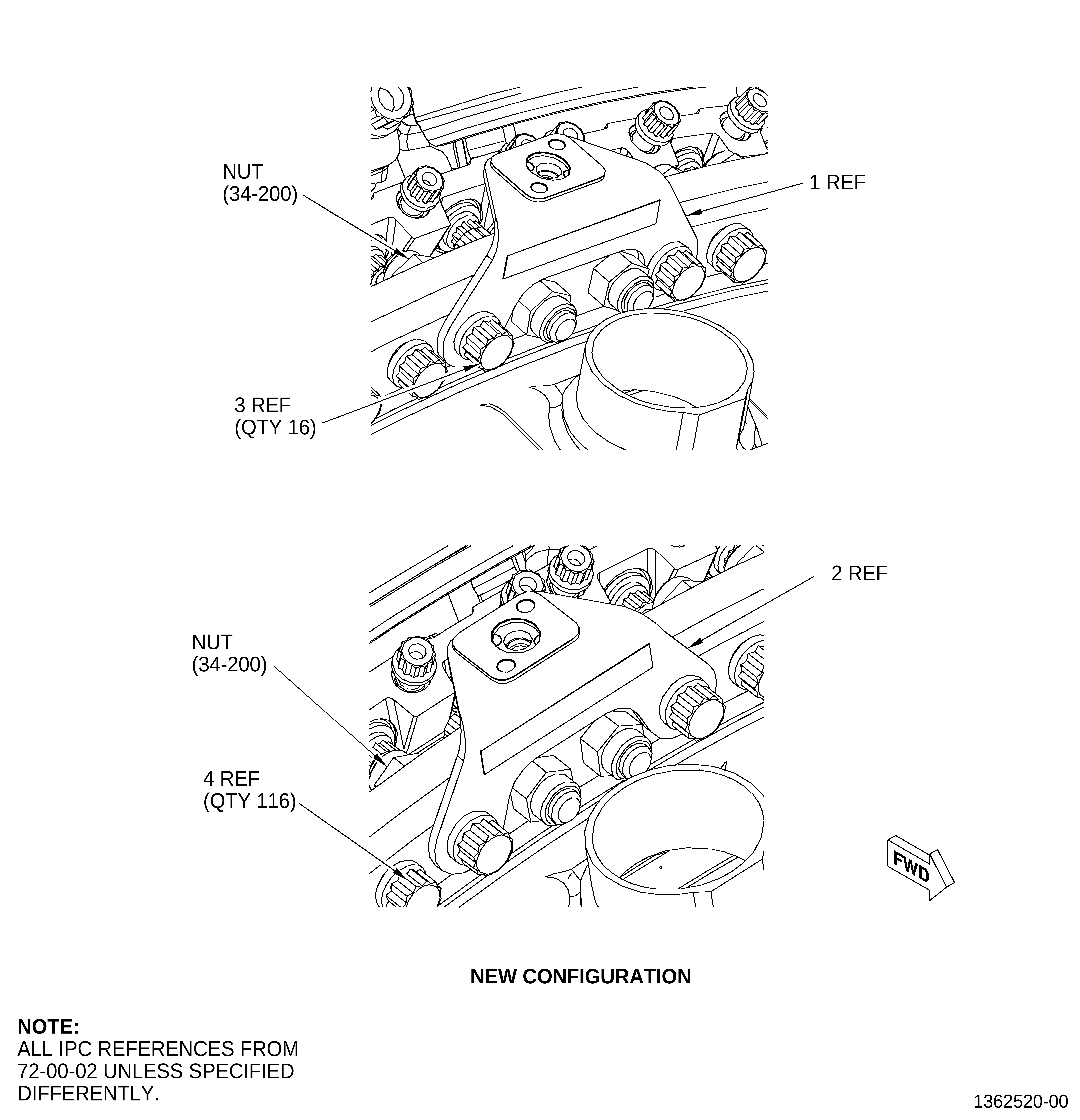
| (2) | Install the brackets (1 and 2, Figure 2) on the HPT stage 2 nozzle assembly (34-011, 72-00-02) as follows: |
| (a) | Install the bracket (1, Figure 2, Sheet 4) at boltholes No. 2 and No. 127 on the forward side of the flanges. |
| (b) | Attach the bracket (1) with the bolts (34-190) and nuts (34-200) with the bolthead forward. Hand tighten the nuts (34-200). |
| (c) | Install the brackets (2, Figure 2, Sheet 4) at boltholes No. 15-18, 31-34, 47-50, 63-66, 79,82, 95-98, and 111-114 on the forward side of the flanges. |
| (d) | Attach the brackets (2) with the bolts (34-190) and nuts (34-200) with the bolthead forward. Hand tighten the nuts (34-200). |
| (e) | Torque the 16 nuts (34-200) in a criss-cross pattern to 368-432 lb in. (41.6-48.8 N.m). |
| (3) | Install the HPTACC manifolds as follows: |
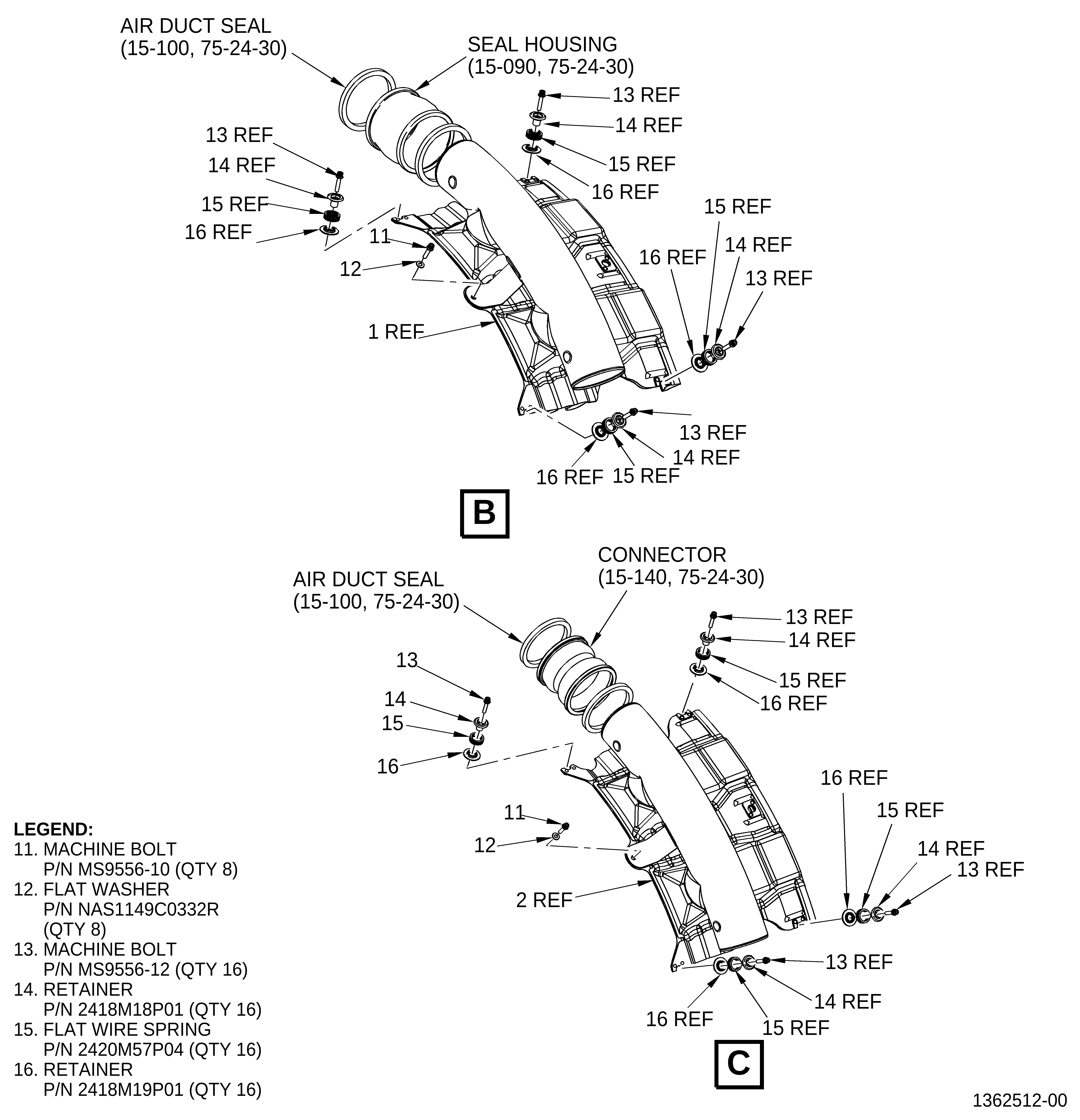
| (a) | Apply C02-008 lubricant inside the grooves of the seal housings (15-090, 75-24-30, Figure 1) and the connector (15-140). |
| (b) | Install an air duct seal (15-100) in each end of the connector (15-140). |
| CAUTION: |
|
| (c) | Install the connector (15-140) on the clockwise end of the HPT air manifold (2, Figure 1, Sheet 3). Push the connector as far as possible onto the HPT air manifold (2). |
| (d) | Put the HPT air manifold (2) on the HPT stator case at the 2 o'clock position aft looking forward (AFT). |
| (e) | Install the machine bolt (11) and the washer (12) at the forward center bolthole and attach the HPT air manifold (2) to the bracket (5, Figure 3, Sheet 3). |
| (f) | Install the flat wire spring (15) between the retainers (14 and 16). |
| (g) | Install the machine bolt (13), the retainers (14 and 16), and the flat wire spring (15) at the forward corner boltholes and attach the HPT air manifold (2) to the bracket (4, Figure 3, Sheet 3). |
| (h) | Install the remaining HPT air manifolds (3, 4, 5, 6, 7, 8, and 1, Figure 1) as follows: |
| 1 | Install an air duct seal (15-100, 75-24-30) in each end of the seal housing (15-090). |
| CAUTION: |
|
| 2 | Install the seal housing (15-090) on the clockwise end of the HPT air manifold (3). Push the seal housing (15-090) as far as possible onto the HPT air manifold (3). |
| 3 | Put the HPT air manifold (3) on the HPT stator case at the 4:00 o'clock position AFT. |
| 4 | Install the machine bolt (11) and the washer (12) at the forward center bolthole and attach the HPT air manifold (3) to the bracket (2, Figure 3). |
| 5 | Install the flat wire spring (15, Figure 1, Sheet 3) between the retainers (14 and 16). |
| 6 | Install the machine bolt (13), the retainers (14 and 16) and the flat wire spring (15) at the forward center bolthole and attach the HPT air manifold (3) to the bracket (3, Figure 3, Sheet 3). |
| 7 | To install the remaining HPT air manifolds (4, 5, 6, 7, 8, and 1, Figure 1) repeat steps 3.B.(3)(h)(1) through 3.B.(3)(h)(6). |
| (i) | When all the manifolds are installed, carefully move the seal housings (15-090 ,75-24-30, Figure 1) and the connector (15-140) in a clockwise direction to connect the adjacent manifold. Be careful not to damage the air duct seal (15-100). |
| (j) | Install the remaining flat wire spring (15) between the retainers (14 and 16). |
| (k) | Install the machine bolt (13), the retainers (14 and 16), and the flat wire spring (15) at the AFT corner boltholes on the HPT air manifolds (1, 2, 3, 4, 5, 6, 7, and 8) and attach the HPT air manifolds (1, 2, 3, 4, 5, 6, 7, and 8) to the brackets (1 and 2, Figure 2, Sheet 3). |
| (l) | Torque the bolts (11 and 13, Figure 1) to 106-124 lb in. (12.0-14.0 N.m). |