| GEnx-1B SERVICE BULLETIN - 75-0006 R00 | Revised: 04/17/2013 | |
| SB 75-0006 R00 AIR - EXCITER AIR COOLING DUCTS (75-23-10) - Introduction of New Configuration Group P/N 2376M20 | Issued: 04/17/2013 | |
| GEnx-1B SERVICE BULLETIN - 75-0006 R00 | Revised: 04/17/2013 | |
| SB 75-0006 R00 AIR - EXCITER AIR COOLING DUCTS (75-23-10) - Introduction of New Configuration Group P/N 2376M20 | Issued: 04/17/2013 | |
| 1. | PLANNING INFORMATION |
| A. | Effectivity |
|
| This Service Bulletin has been introduced in production to these GEnx-1B engines: |
| • |
|
| These serial numbers are the best available data. |
| The seal ring P/N 1847M57P01, loop clamp P/N MS9025-10, seal retainer P/N 2327M99G01, seal retainer P/N 2379M75G01, and machine bolt P/N AS3237-12 are affected by this Service Bulletin. |
| B. | Description |
| This Service Bulletin provides an update for the GEnx-1B propulsor assembly configuration. |
| C. | Compliance |
| Category 7 |
| GE recommends that you do this Service Bulletin at customer's convenience or option. |
| NOTE: |
|
| D. | Concurrent Requirements |
| None. |
| E. | Reason |
| (1) | Objective: |
| To introduce new parts. |
| To properly update the GEnx-1B propulsor assembly configuration. |
| (2) | Condition: |
| Some of the GEnx-1B configuration updates were not made to some modules groups. |
| (3) | Cause: |
| The affected group does not contain the current GEnx configuration. |
| (4) | Improvement: |
| This Service Bulletin updates P/N 2376M20 module groups to properly reflect the GEnx-1B configuration. |
| (5) | Substantiation: |
| Substantiation is by analysis and test. |
| F. | Approval |
| This Service Bulletin has been reviewed by the appropriate governmental authority and the repair(s) and modification(s) herein comply with the applicable Aviation Regulations and are APPROVED for installation in the model(s) listed in this Service Bulletin. |
| G. | Manpower |
| No additional man-hours are required to comply with this Service Bulletin. |
| H. | Weight and Balance |
| Weight and balance are not changed. |
| I. | References(Use the latest version of this document) |
| GEK 112864, GEnx-1B Engine Illustrated Parts Catalog (EIPC) |
| NOTE: |
|
| J. | Publications Affected |
| GEK 112851, GEnx-1B Engine Manual (EM) |
| GEK 112864, GEnx-1B Engine Illustrated Parts Catalog (EIPC) |
| K. | Interchangeability |
| Qualified interchangeability: The quantity of the seal retainer SIN 62010 and cushion loop clamp SIN 52180 is changing. |
| L. | Software Accomplishment Summary |
| Not applicable. |
| 2. | MATERIAL INFORMATION |
| A. | Material - Price and Availability |
| (1) | Parts necessary to do this Service Bulletin: |
|
| * Part not supplied by GE Engine Services Distribution L.L.C. Procure through local purchase. |
| NP= Not Provisioned |
| NOTE: |
|
| (2) | Other Spare Parts: |
| None. |
| (3) | Consumables: |
| None. |
| B. | Industry Support Information |
| None. |
| C. | Configuration Chart |
|
| Operation Codes DE=Delete RE=Replace RM=Remains QTC=Quantity Change |
| Change Codes 2=Two-way interchangeable. 5=Qualified interchangeability. Refer to paragraph 1.K., Interchangeability. |
| Support Codes B=Old parts will be supplied until all old parts are sold. E=Old parts will be supplied, and can be used at other engine locations. |
| D. | Parts Disposition |
| Use serviceable old parts at other engine locations. |
| E. | Tooling - Price and Availability |
| None. |
| 3. | ACCOMPLISHMENT INSTRUCTIONS |
| A. | Removal |
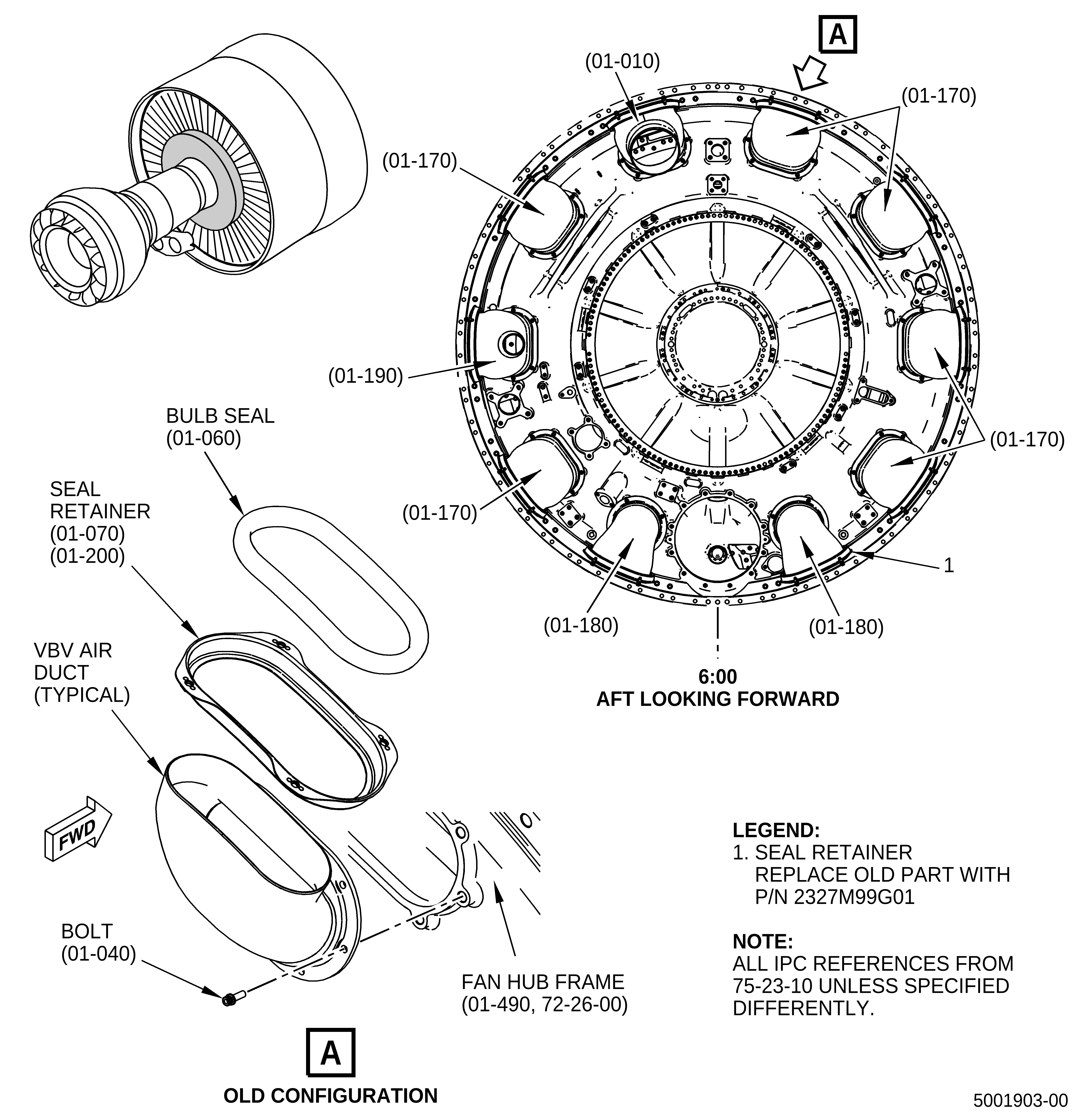
| (1) | Remove the seal retainers (01-070, 75-23-10), seal retainer (01-200), and bulb seals (01-060) from the VBV air ducts. Refer to the GEnx-1B EM, 72-00-02, DISASSEMBLY 002, Subtask 72-00-02-040-138, except as follows: |
| (a) | Remove the seal retainer (01-200) and bulb seal (01-060) from the VBV air duct (01-180) at the 5:00 o'clock position. Discard the seal retainer. |
| (2) | Removal instructions of the bolts (65-160, 72-00-02), have not changed. Refer to the GEnx-1B EM, 72-00-02, DISASSEMBLY 001, Subtask 72-00-02-030-438. |
| (3) | Remove the cushion loop clamps (30-140, 79-22-10), refer to the GEnx-1B EM, 72-00-02, DISASSEMBLY 002, Subtask 72-00-02-030-417. |
| B. | Assembly |
| (1) | Install the seal retainers on the VBV air ducts. Refer to the GEnx-1B EM, 72-00-02, ASSEMBLY 004, Subtask 72-00-02-440-130, except as follows: |
| (a) | Replace seal retainer (01-200) with the seal retainer (1, Figure 1) on the VBV air duct (01-180) at the 5:00 o'clock position on the fan hub frame (01-490, 72-26-00). |
| (2) | Installation instructions of the bolts (65-160, 72-00-02), have not changed. Refer to the GEnx-1B EM, 72-00-02, ASSEMBLY 006, Subtask 72-00-02-430-767. |
| (3) | Install the cushion loop clamps (30-140A, 79-22-10), refer to the GEnx-1B EM, 72-00-02, ASSEMBLY 005, Subtask 72-00-02-440-184. |