| GEnx-1B SERVICE BULLETIN - 75-0012 R00 | Revised: 10/10/2014 | |
| SB 75-0012 R00 AIR - LPT ACC Manifolds (75-24-10) - Release of New Air Manifolds with V-Band Coupling Clamp | Issued: 10/10/2014 | |
| GEnx-1B SERVICE BULLETIN - 75-0012 R00 | Revised: 10/10/2014 | |
| SB 75-0012 R00 AIR - LPT ACC Manifolds (75-24-10) - Release of New Air Manifolds with V-Band Coupling Clamp | Issued: 10/10/2014 | |
| GE PROPRIETARY INFORMATION | |
| The information contained in this document is GE proprietary information and is disclosed in confidence. It is the property of GE and shall not be used, disclosed to others or reproduced without the express written consent of GE, including, but without limitation, it is not to be used in the creation, manufacture, development, or derivation of any repairs, modifications, spare parts, designs, or configuration changes or to obtain FAA or any other government or regulatory approval to do so. If consent is given for reproduction in whole or in part, this notice and the notice set forth on each page of this document shall appear in any such reproduction in whole or in part. | |
| This technical data is considered EAR controlled pursuant to 15 CFR Parts 730-774 respectively. Transfer of this data by any means to a Non-US Person, whether in the United States or abroad, without the proper U.S. Government authorization (e.g., License, exemption, NLR, etc.), is strictly prohibited. | |
| Copyright (2014) General Electric Company, U.S.A. |
| 1. | PLANNING INFORMATION |
| A. | Effectivity |
| * * * FOR GEnx-1B54, -1B54/P1, -1B54/P2, -1B58, -1B58/P1, -1B58/P2, -1B64, -1B64/P1, -1B64/P2, -1B67, -1B67/P1, -1B67/P2, -1B70, -1B70/72/P1, -1B70/72/P2, -1B70/75/P1, -1B70/75/P2, -1B70/P1, -1B70/P2, -1B74/75/P1, -1B74/75/P2, -1B75/P1, -1B75/P2, -1B78/P2 |
| This Service Bulletin has been introduced in production to these GEnx-1B engines: |
| • |
|
| These serial numbers are the best available data. |
| The 4th stage air manifold (air manifold) P/N 2489M97G01 is affected by this Service Bulletin. |
| B. | Description |
| This Service Bulletin releases new 4th stage air manifold (air manifold) P/N 2567M00G01 and new 4th stage air manifold (air manifold) P/N 2567M01G01, ring seal P/N AS1895/23-125, coupling clamp (V-band coupling) P/N AS1895/4-125 and provides instructions to install the new parts. |
| C. | Compliance |
| Category 7 |
| GE recommends that you do this Service Bulletin at customer's convenience/option. |
| NOTE: |
|
| D. | Concurrent Requirements |
| None. |
| E. | Reason |
| (1) | Objective: |
| To introduce new parts and improve maintainability. |
| (2) | Condition: |
| The current air manifold is difficult to assemble. This condition has caused increased assembly time due to excessive preferential assembly and effort required to align the 4-bolt flange on the turbine center frame (TCF) and manufacturing delays. |
| (3) | Cause: |
| The current design consists of 4 coupling clamp connections and one 4-bolt flange. The stack-up variation of all of these joints results in a condition where the 4-bolt flange does not align correctly the majority of the time. |
| (4) | Improvement: |
| The proposed design adds an additional rotational degree of freedom to the 4-bolt flange connector at the TCF. Additionally, the V-band coupling flange allows for some axial flexibility in assembling the hardware. |
| (5) | Substantiation: |
| Substantiation is by comparative analysis. |
| F. | Approval |
| This Service Bulletin has been reviewed by the FAA and the repair(s) and modification(s) herein comply with the applicable Federal Aviation Regulations and are FAA APPROVED for installation in the model(s) listed in this Service Bulletin. |
| G. | Manpower |
| After you get access to the air manifold, you will need approximately 0.5 man-hour for each engine or component. |
| H. | Weight and Balance |
| The complete compliance with this Service Bulletin increases weight by 1.43 lb (0.65 kg). |
| I. | References (Use the latest version of these documents) |
| GEK 112851, GEnx-1B Engine Manual (EM) |
| GEK 112862, GEnx-1B Cleaning, Inspection, and Repair Manual (CIR) |
| GEK 112864, GEnx-1B Engine Illustrated Parts Catalog (EIPC) |
| NOTE: |
|
| J. | Publications Affected |
| GEK 112851, GEnx-1B Engine Manual (EM) |
| GEK 112862, GEnx-1B Cleaning, Inspection, and Repair Manual (CIR) |
| GEK 112864, GEnx-1B Engine Illustrated Parts Catalog (EIPC) |
| K. | Interchangeability |
| The new parts must be introduced in a complete set. New parts cannot be mixed with old parts. It is not necessary that all three affected engine locations have the new manifold configuration installed at the same time. |
| L. | Software Accomplishment Summary |
| Not applicable. |
| 2. | MATERIAL INFORMATION |
| A. | Material - Price and Availability |
| (1) | Parts necessary to do this Service Bulletin: |
|
| NP= Not Provisioned |
| *Part not supplied by GE Engine Services Distribution L.L.C. Procure through local purchase. |
| NOTE: |
|
| (2) | Other Spare Parts: |
| None. |
| (3) | Consumables: |
| None. |
| B. | Industry Support Information |
| None. |
| C. | Configuration Chart |
|
| Operation Codes AD=Add RE=Replace RM=Remains |
| Change Code 5=Qualified interchangeability. Refer to paragraph 1.K., Interchangeability. |
| Support Code B=Old parts will be supplied until all old parts are sold. |
| D. | Parts Disposition |
| None. |
| E. | Tooling - Price and Availability |
| None. |
| 3. | ACCOMPLISHMENT INSTRUCTIONS |
| A. | Removal of the Air Manifold |
| NOTE: |
|
| NOTE: |
|
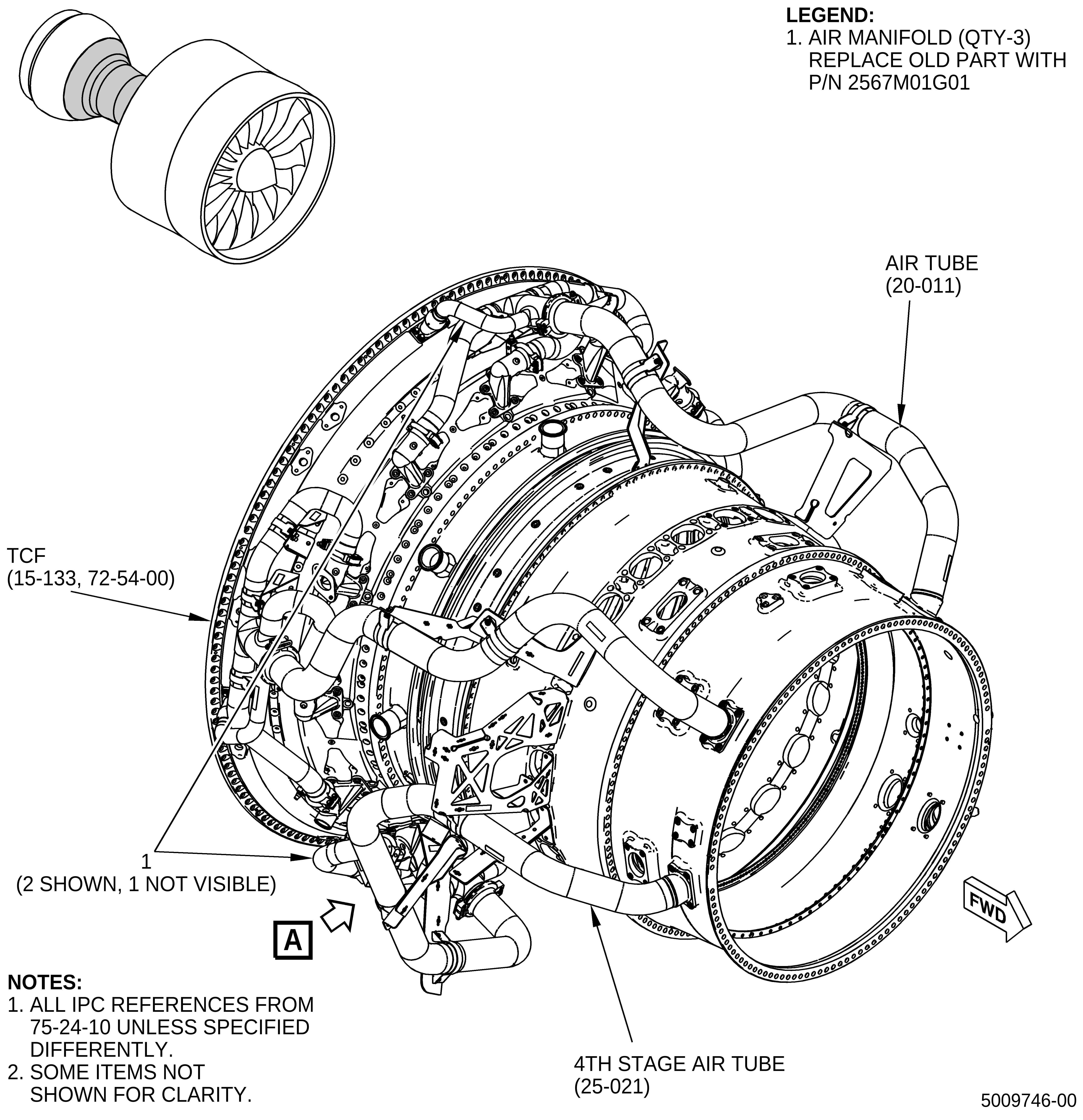
| (1) | Remove the old air manifold (1, Figure 1) from the TCF (15-133, 72-54-00). Refer to the GEnx-1B EM, 72-00-02, DISASSEMBLY 003, Subtask 72-00-02-030-394. |
| B. | Installation of the Air Manifold |
| NOTE: |
|
| (1) | Install the air manifold (1, Figure 1) on the lower left side of the TCF (15-133, 72-54-00) as follows: |
| (a) | Install the air manifold (20-021, 75-24-10) on the lower left side. Refer to the GEnx-1B EM, 72-00-02, ASSEMBLY 004, CONFIGURATION 01, Subtask 72-00-02-440-282 from paragraphs 3.R.A.(3)(a) to 3.R.A.(3)(g). |
| (b) | Install the new ring seal (4, Figure 1) into the forward side of the new air manifold (3). |
| (c) | Install a metal seal ring (seal) (20-110, 75-24-10) on the aft end of the new air manifold (3, Figure 1). |
| (d) | Install the new air manifold (3) on the TCF. Attach the aft end of the new air manifold (3) with double hexagonal head machine bolts (bolts) (20-100, 75-24-10). |
| (e) | Connect the new air manifold (1, Figure 1) to the new air manifold (3). |
| (f) | Attach the forward end of the new air manifold (3) with the new V-band coupling (2). Install the new V-band coupling (2) with the nut aft and outboard. |
| (g) | Continue the installation of the air manifold (20-021, 75-24-10) on the lower left side. Refer to the GEnx-1B EM, 72-00-02, ASSEMBLY 004, CONFIGURATION 01, Subtask 72-00-02-440-282 from paragraphs 3.R.A.(3)(k) to 3.R.A.(3)(u) and Subtask 72-00-02-440-283. |
| (2) | Install the air manifold (1, Figure 1) on upper left side of the TCF (15-133, 72-54-00) as follows: |
| (a) | Install the stage 4 air tube (air tube) (20-011, 75-24-10) on the upper left side. Refer to the GEnx-1B EM, 72-00-02, ASSEMBLY 004, CONFIGURATION 01, Subtask 72-00-02-440-283 from paragraphs 3.R.A.(4)(a) to 3.R.A.(4)(g). |
| (b) | Install the new ring seal (4, Figure 1) into the forward side of the new air manifold (3). |
| (c) | Install a seal (20-110, 75-24-10) on the aft end of the new air manifold (3, Figure 1). |
| (d) | Install the new air manifold (3) on the TCF. Attach the aft end of the new air manifold (3) with bolts (20-100, 75-24-10). |
| (e) | Connect the new air manifold (1, Figure 1) to the new air manifold (3). |
| (f) | Attach the forward end of the new air manifold (3) with the new V-band coupling (2). Install the new V-band coupling (2) with the nut aft and outboard. |
| (g) | Continue the installation of the air tube (20-011, 75-24-10) on the upper left side. Refer to the GEnx-1B EM, 72-00-02, ASSEMBLY 004, CONFIGURATION 01, Subtask 72-00-02-440-283 from paragraphs 3.R.A.(4)(k) to 3.R.A.(4)(u). |
| (3) | Install the air manifold (25-042, 75-24-10) on the lower right side of the TCF (15-133, 72-54-00). |
| (a) | Install the stage 4 air tube (air tube) (25-021, 75-24-10) on the lower right side. Refer to the GEnx-1B EM, 72-00-02, ASSEMBLY 004, CONFIGURATION 01, Subtask 72-00-02-440-281 from paragraphs 3.R.A.(2)(a) to 3.R.A.(2)(g). |
| (b) | Install the new ring seal (4, Figure 1) into the forward side of the new air manifold (3). |
| (c) | Install a metal ring seal (25-130, 75-24-10) on the aft end of the new air manifold (3, Figure 1). |
| (d) | Install the new air manifold (3) on the TCF. Attach the aft end of the new air manifold (3) with double hexagonal head machine bolts (25-120, 75-24-10). |
| (e) | Connect the new air manifold (1, Figure 1) to the new air manifold (3). |
| (f) | Attach the forward end of the new air manifold (3) with the new V-band coupling (2). Install the new V-band coupling (2) with the nut aft and outboard. |
| (g) | Continue the installation of the air tube (25-021, 75-24-10) on the lower right side. Refer to the GEnx-1B EM, 72-00-02, ASSEMBLY 004, CONFIGURATION 01, Subtask 72-00-02-440-281 from paragraphs 3.R.A.(2)(l) to 3.R.A.(2)(v). |