| GEnx-1B SERVICE BULLETIN - 75-0014 R04 | Revised: 03/21/2018 | |
| SB 75-0014 R04 AIR - Transient Bleed Air Duct (75-31-21) - Introduction of New Transient Bleed Valve Duct Assembly | Issued: 01/22/2015 | |
| GEnx-1B SERVICE BULLETIN - 75-0014 R04 | Revised: 03/21/2018 | |
| SB 75-0014 R04 AIR - Transient Bleed Air Duct (75-31-21) - Introduction of New Transient Bleed Valve Duct Assembly | Issued: 01/22/2015 | |
| GE PROPRIETARY INFORMATION | |
| The information contained in this document is GE proprietary information and is disclosed in confidence. It is the property of GE and shall not be used, disclosed to others or reproduced without the express written consent of GE, including, but without limitation, it is not to be used in the creation, manufacture, development, or derivation of any repairs, modifications, spare parts, designs, or configuration changes or to obtain FAA or any other government or regulatory approval to do so. If consent is given for reproduction in whole or in part, this notice and the notice set forth on each page of this document shall appear in any such reproduction in whole or in part. | |
| This technical data is considered EAR controlled pursuant to 15 CFR Parts 730-774 respectively. Transfer of this data by any means to a Non-US Person, whether in the United States or abroad, without the proper U.S. Government authorization (e.g., License, exemption, NLR, etc.), is strictly prohibited. | |
| Copyright (2018) General Electric Company, U.S.A. |
| TRANSMITTAL INFORMATION |
| REVISION 4 TO SERVICE BULLETIN 75-0014 |
| Revision 4 is issued to update paragraphs 1., PLANNING INFORMATION and 2., MATERIAL INFORMATION. |
| Revision 3 was issued October 12, 2016. Revision 2 was issued April 15, 2016. Revision 1 was issued January 08, 2016. The original was issued January 22, 2015. Revision bars in the left margin identify changes. |
| 1. | PLANNING INFORMATION |
| A. | Effectivity |
| * * * FOR GEnx-1B64, -1B64/P1, -1B64/P2, -1B67, -1B67/P1, -1B67/P2, -1B70, -1B70/75/P1, -1B70/75/P2, -1B70/P1, -1B70/P2, -1B74/75/P1, -1B74/75/P2 |
| This Service Bulletin has been introduced in production to these GEnx-1B engines: |
| • |
|
| These serial numbers are the best available data. |
| The gasket P/N 2409M84P01 and bulb seal P/N 2365M78P01 are affected by this Service Bulletin. |
| B. | Description |
| This Service Bulletin releases a new gasket P/N 2629M78P01, heat shield P/N 2629M79G01, bulb seal P/N 2550M20P02, transient bleed valve (TBV) outer insulation (outer insulation blanket) P/N 2629M90P01, TBV inner insulation (inner insulation blanket) P/N 2629M91P01, and machine bolts (bolts) P/N AS3237-08. |
| C. | Compliance |
| Category 7 |
| GE recommends that you do this Service Bulletin at customer's convenience or option. |
| Impact E |
| This recommendation is to improve the cost of ownership, reduce maintenance requirements or is a product improvement. |
| NOTE: |
|
| D. | Concurrent Requirements |
| None. |
| E. | Reason |
| (1) | Objective: |
| To introduce new parts. |
| (2) | Condition: |
| The current design of the bulb seal does not always allow 360-degree contact with the thrust reverser seal landing. Additionally, the current bulb seal assembly does not comply with the 74K rating that the engine requires for this configuration. |
| (3) | Cause: |
| The outer section of the current bulb seal is too stiff to always conform to the thrust reverser sealing landing. |
| (4) | Improvement: |
| The outer section of the new bulb seal is thinner to allow more flexibility. In addition, flexible rings are added to the inner and outer diameters of the bulb seal to provide secondary sealing surfaces with the thrust reverser seal landing. Additionally, the new bulb seal assembly configuration is necessary for the 74k rating compliance. |
| (5) | Substantiation: |
| Substantiation is by comparative analysis and test. |
| F. | Approval |
| The data contained in this Service Bulletin has been reviewed by the appropriate governmental authority and the repair(s) and modification(s) herein comply with the applicable Aviation Regulations and are APPROVED for installation in the model(s) listed in this Service Bulletin. |
| G. | Manpower |
| After you get access to the transient bleed air duct, you will need approximately 4.0 man-hours to do the replacement portion of this Service Bulletin. |
| H. | Weight and Balance |
| The complete compliance with this Service Bulletin increases weight by 5.3 lb (2.4 kg). |
| I. | References (Use the latest version of these documents) |
| GEK 112851, GEnx-1B Engine Manual (EM) |
| GEK 112864, GEnx-1B Engine Illustrated Parts Catalog (EIPC) |
| NOTE: |
|
| J. | Publications Affected |
| GEK 112851, GEnx-1B Engine Manual (EM) |
| GEK 112864, GEnx-1B Engine Illustrated Parts Catalog (EIPC) |
| K. | Interchangeability |
| All parts associated with this change must be introduced as a complete engine set. |
| L. | Software Accomplishment Summary |
| Not applicable. |
| 2. | MATERIAL INFORMATION |
| A. | Material - Price and Availability |
| (1) | Parts necessary to do this Service Bulletin: |
|
| *Part not supplied by GE Engine Service Distribution L.L.C. Procure through local purchase. |
| NP=Not Provisioned |
| NOTE: |
|
| (2) | Other Spare Parts: |
|
| *Part not supplied by GE Engine Service Distribution L.L.C. Procure through local purchase. |
| NP=Not Provisioned |
| NOTE: |
|
| (3) | Consumables: |
| None. |
| B. | Industry Support Information |
| None. |
| C. | Configuration Chart |
|
| Operation Codes AD=Add RE=Replace RM=Remains |
| Change Code 5=Qualified interchangeability. Refer to paragraph 1.K., Interchangeability. |
| Support Code D=Old parts will be supplied for engines that have not been changed by this Service Bulletin. |
| D. | Parts Disposition |
| None. |
| E. | Tooling - Price and Availability |
| None. |
| 3. | ACCOMPLISHMENT INSTRUCTIONS |
| A. | Removal of the TBV Duct Assembly |
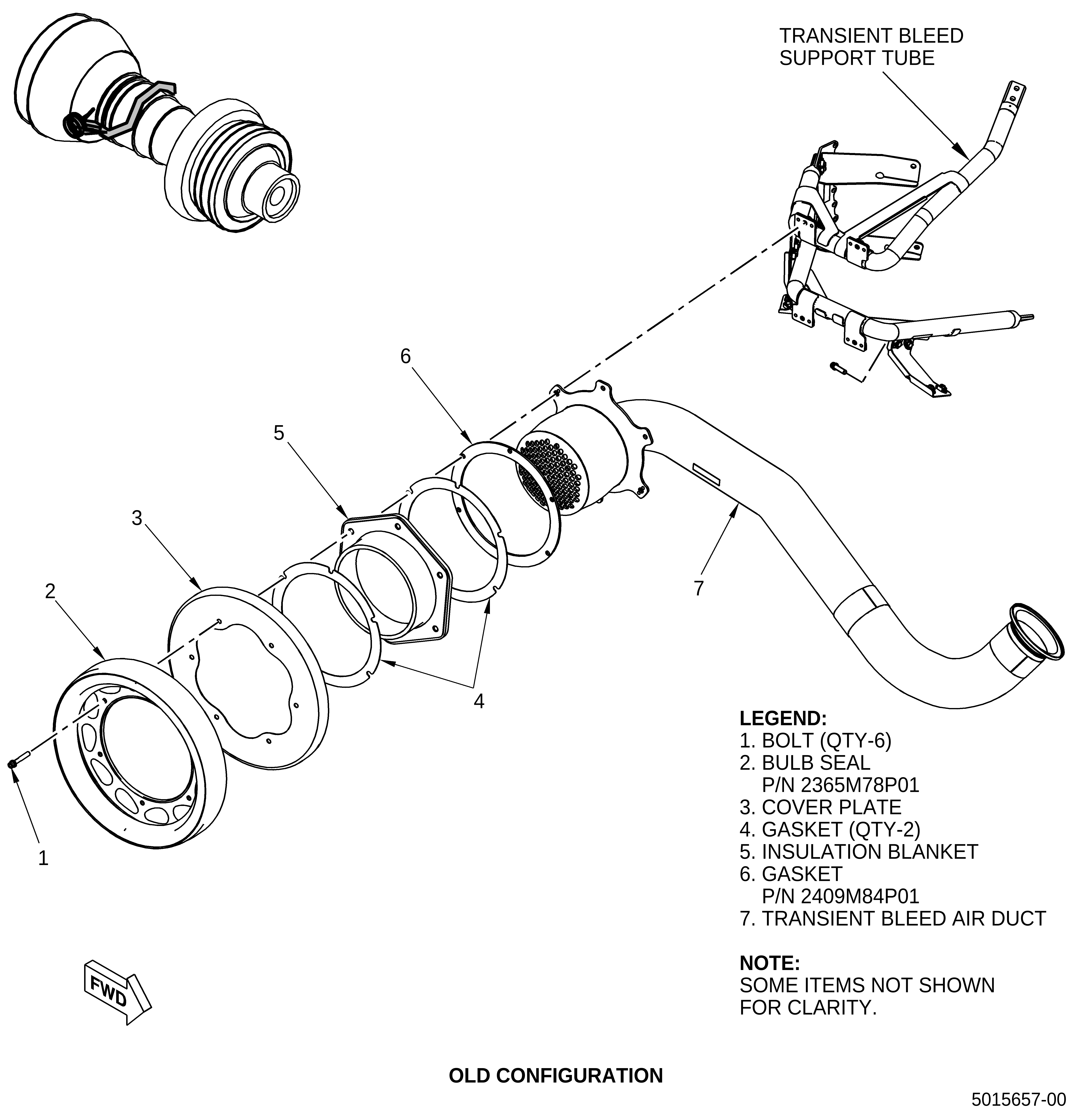
| (1) | Remove the six machine bolts (bolts) (1, Figure 1) from the bulb seal (2). Keep the six bolts (1) to install them again later. |
| (2) | Remove and discard the bulb seal (2). |
| (3) | Remove the cover plate (3) and keep it to install again later. |
| (4) | Remove and discard the gasket (4). |
| (5) | Remove the insulation blanket (5) and keep it to install it again later. |
| (6) | Remove and discard the gasket (4). |
| (7) | Remove and discard the gasket (6) from the transient bleed air duct (7). |
| B. | Installation of the TBV Duct Assembly |
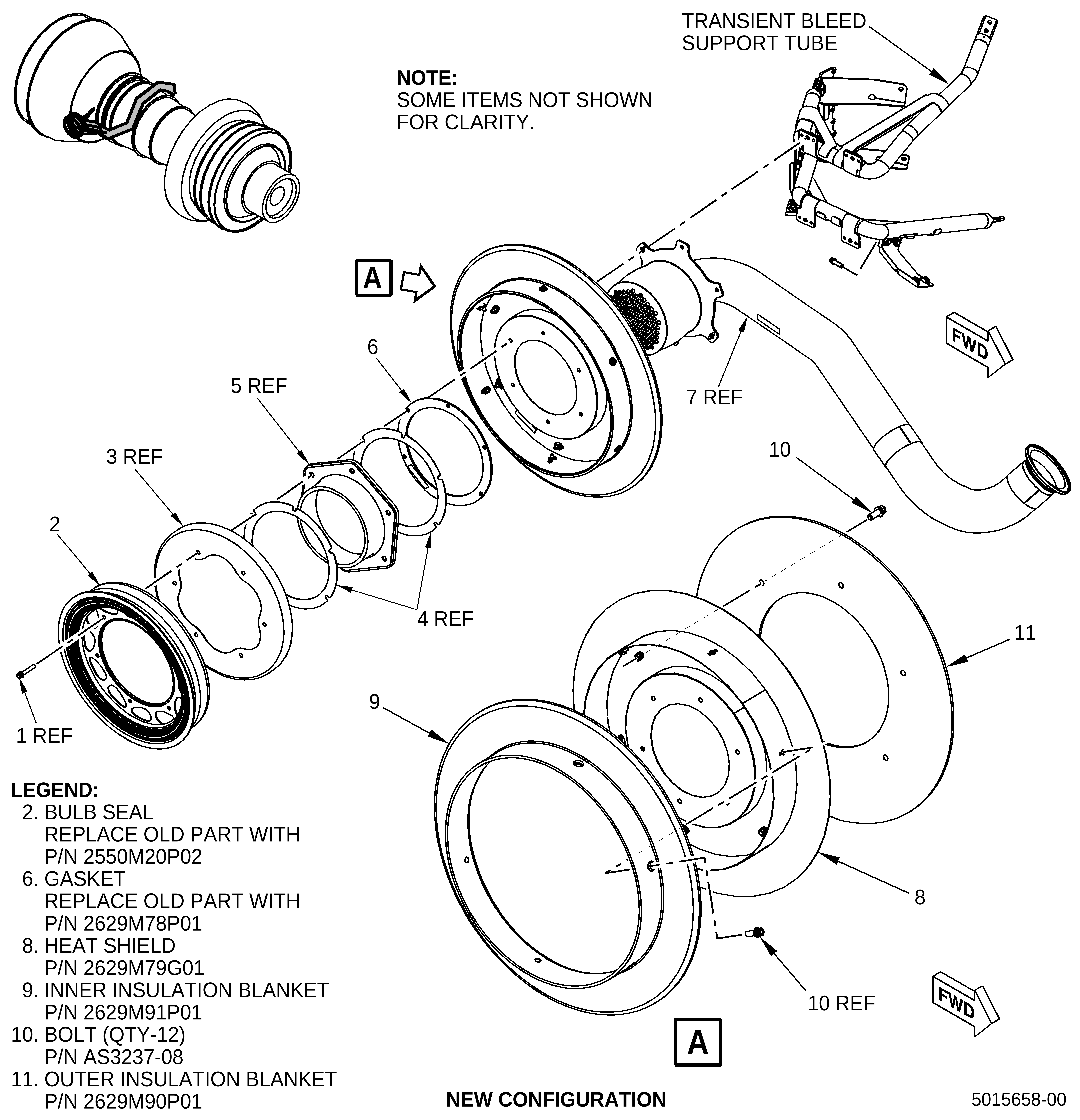
| (1) | Install the heat shield (8, Figure 1) into the inner insulation blanket (9) with the boltholes aligned. |
| (2) | Install six machine bolts (bolts) (10) radially through the inner insulation blanket (9) into the heat shield (8). |
| (3) | Install the outer insulation blanket (11) into the heat shield (8) with the boltholes aligned. |
| (4) | Install six bolts (10) axially through the outer insulation blanket (11) into the heat shield (8). |
| (5) | Torque the 12 bolts (10) to 106 to 124 lb in. (11.9 to 14.0 Nm). |
| NOTE: |
|
| (6) | Put the heat shield assembly onto the transient bleed air duct (7) with the inner bolthole circles aligned with the transient bleed air duct (7) boltholes. |
| (7) | Install a new gasket (6) on top of the heal shield assembly with the boltholes aligned. |
| (8) | Install a new gasket (4) with the boltholes aligned. |
| (9) | Install the insulation blanket (5) with the boltholes aligned. |
| (10) | Install a new gasket (4) with the boltholes aligned. |
| (11) | Install the cover plate (3). |
| (12) | Install a new bulb seal (2) with the boltholes aligned. |
| (13) | Tightly attach the new bulb seal (2), gaskets (4), heat shield assembly, gasket (6), insulation blanket (5), cover plate (3), and transient bleed air duct (7) onto the nut plates with the six bolts (1). |
| (14) | Torque the bolts (1) to 106 to 124 lb in. (11.9 to 14.0 Nm). |