| GEnx-1B SERVICE BULLETIN - 75-0035 R01 | Revised: 07/25/2024 | |
| SB 75-0035 R01 AIR - PS25 Pressure Sense Tubes (75-42-15) - Removal of the PS25 Sense Tube and P25 Hose Tube from the Fan Case Module Assembly | Issued: 08/13/2018 | |
| GEnx-1B SERVICE BULLETIN - 75-0035 R01 | Revised: 07/25/2024 | |
| SB 75-0035 R01 AIR - PS25 Pressure Sense Tubes (75-42-15) - Removal of the PS25 Sense Tube and P25 Hose Tube from the Fan Case Module Assembly | Issued: 08/13/2018 | |
| GE Designated: -CONFIDENTIAL- | |
| The information contained in this document is GE proprietary information and is disclosed in confidence. It is the property of GE and shall not be used, disclosed to others or reproduced without the express written consent of GE, including, but without limitation, it is not to be used in the creation, manufacture, development, or derivation of any repairs, modifications, spare parts, designs, or configuration changes or to obtain FAA or any other government or regulatory approval to do so. If consent is given for reproduction in whole or in part, this notice and the notice set forth on each page of this document shall appear in any such reproduction in whole or part. | |
| This technical data is considered subject to the Export Administration Regulations (EAR) pursuant to 15 CFR Parts 730-774. Transfer of this data by any means to a Non-U.S. Person, whether in the United States or abroad, without the proper U.S. Government authorization (e.g., License, exemption, NLR, etc.), is strictly prohibited. | |
| Copyright (2024) General Electric Company, U.S.A. |
| TRANSMITTAL INFORMATION |
| REVISION 1 TO SERVICE BULLETIN 75-0035 |
| Revision 1 is issued to update paragraphs 2., MATERIAL INFORMATION and 3., ACCOMPLISHMENT INSTRUCTIONS. |
| The original was issued August 13, 2018. Revision bars in the left margin identify changes. |
| 1. | PLANNING INFORMATION |
| A. | Effectivity |
| * * * FOR GEnx-1B64, -1B64/P1, -1B64/P2, -1B67, -1B67/P1, -1B67/P2, -1B70, -1B70/75/P1, -1B70/75/P2, -1B70/P1, -1B70/P2, -1B70C/P1, -1B70C/P2, -1B74/75/P1, -1B74/75/P2, -1B76A/P2 |
| This Service Bulletin has been introduced in production to these GEnx-1B engines: |
| • |
|
| These serial numbers are the best available data. |
| The PS25 pressure sense tube (PS25 sense tube) P/N 2409M96G01 , air P25 hose tubes (P25 hose tubes) P/N 2365M41P01 and P/N 2365M41P02, cushion loop clamp (loop clamp) P/N J1432P06, and machine bolt P/N MS9556-06 are affected by this Service Bulletin. |
| B. | Description |
| This Service Bulletin provides instructions to eliminate the affected PS25 sense tube, P25 hose tube, and their attaching loop clamps from the fan stator module assembly. |
| This Service Bulletin also introduces the new tube cap P/N J1315G106 . |
| C. | Compliance |
| Category 7 |
| GE recommends that you do this Service Bulletin at customer's convenience. |
| Impact F |
| Implement as deemed necessary per the Service Bulletin Category. |
| NOTE: |
|
| D. | Concurrent Requirements |
| None. |
| E. | Reason |
| (1) | Objective: |
| To remove parts from service. |
| (2) | Condition: |
| Currently, the PS25 sense tube is no longer used in the control logic due to the electronic engine control (EEC) software upgraded version B140. The interconnecting PS25 sense tube and P25 hose tube are adding extra weight to the engine. |
| (3) | Cause: |
| The PS25 sensor functionality was eliminated in the software version B140 and up. This PS25 sensor is not used in the EEC control logic or engine condition monitoring. |
| (4) | Improvement: |
| The proposed design change will remove the unnecessary PS25 sense tube, P25 hose tube, and their attaching loop clamps. It will also add a standard tube cap on the PS25 sense tube fitting at the lower bifurcation assembly. |
| (5) | Substantiation: |
| Substantiation is by analysis and comparative analysis. |
| F. | Approval |
| The data contained in this Service Bulletin has been reviewed by the FAA or authorized entity representing the FAA and the repair(s) and modification(s) herein comply with the applicable Aviation Regulations and are APPROVED for installation in the model(s) listed in this Service Bulletin. |
| G. | Manpower |
| After you get access to the fan stator module assembly, you will need approximately 2.5 man-hours for each engine or component. |
| H. | Weight and Balance |
| The complete compliance with this Service Bulletin decreases weight by 1.53 lb (0.69 kg). |
| I. | References (Use the latest version of these documents) |
| GEnx-1B, Boeing 787 Aircraft Maintenance Manual (AMM) |
| GEK 9250, Commercial Engine Standard Practices Manual (SPM) |
| GEK 112851, GEnx-1B Engine Manual (EM) |
| GEK 112862, GEnx-1B Cleaning, Inspection, and Repair Manual (CIR) |
| GEK 112864, GEnx-1B Engine Illustrated Parts Catalog (EIPC) |
| NOTE: |
|
| J. | Publications Affected |
| GEK 112851, GEnx-1B Engine Manual (EM) |
| GEK 112862, GEnx-1B Cleaning, Inspection, and Repair Manual (CIR) |
| GEK 112864, GEnx-1B Engine Illustrated Parts Catalog (EIPC) |
| K. | Interchangeability |
| Qualified interchangeability - Added and deleted parts. |
| L. | Software Accomplishment Summary |
| Not applicable. |
| 2. | MATERIAL INFORMATION |
| A. | Material - Price and Availability |
| (1) | Parts necessary to do this Service Bulletin: |
|
| NOTE: |
|
| (2) | Other Spare Parts: |
| None. |
| (3) | Consumables: |
|
| B. | Industry Support Information |
| None. |
| C. | Configuration Chart |
|
|||||||||||||||||||||||||||||||||||||||||||||||||||||||||||||||||||||||||||||||||||||||||||||||||||||||||||||||||||||||||||||||||||||||||||||||||||||||||||||||||||||||||||||||||||||||||||||||||||||||||||||||||||||||||||||||||||||||||||||||||||||||||||||||||||||||||||||||||||||||||||||||||||||||||||||||||||||||||||||||||||||||||||||||||||||||||||||||||||||||||||||||||||||||||||||||||||||||||||||||||||||||||||||||||||||||||||||||||||||||||||||||||||||||||||||||||||||||||||||||||||||||||||||||||||||||||||||||||||||||||||||||||||||||||||||||||||||||||||||||||||||||||||||||||||||||||||||||||||||||||||||||||||||||||||||||||||||||||||||||||||||||||||||||||||||||||||||||||||||||||||||||||||||||||||||||||||||||||||||||||||||||||||||||||||||||||||||||||||||||||||||||||||||||||||||||||||||||||||||||||||||||||||||||||||||||||||||||||||||||||||||||||||||||||||||||||||||||||||||||||||||||||||||||||||||||||||||||||||||||||||||||||||||||||||||||||||||||||||||||||||||||||||||||||||||||||||||||||||||||
| Operation Codes AD=Add DE=Delete RM=Remains RW=Rework |
| Change Codes 5=Qualified interchangeability. Refer to paragraph 1.K., Interchangeability. |
| Support Codes A=Old parts will no longer be supplied. B=Old parts will be supplied until all old parts are sold. E=Old parts will be supplied, and can be used at other engine locations. |
| D. | Parts Disposition |
| Use serviceable old parts at other engine locations. |
| Discard old parts. |
| E. | Tooling - Price and Availability |
| None. |
| 3. | ACCOMPLISHMENT INSTRUCTIONS |
| A. | General |
| (1) | If the engine is on wing, refer to the paragraphs 3.B., On-Wing Preparation, 3.C., On-Wing Removal, 3.D., On-Wing Installation, and 3.E., Aircraft Return to Service for the removal of the PS25 sense tube and P25 hose tube from the fan case module assembly. |
| (2) | If the engine is in shop, refer to the paragraphs 3.F., In-Shop Removal and 3.G., In-Shop Installation for the removal of the PS25 sense tube and P25 hose tube from the fan case module assembly. |
| B. | On-Wing Preparation |
| (1) | Do these steps to make sure that the ENGINE START switch and the FUEL CONTROL switch are not operated: |
| (a) | On the pilot's overhead panel, P5, make sure that the applicable ENGINE START switch is in the NORM position. |
| (b) | Put a DO-NOT-OPERATE tag on the applicable ENGINE START switch. |
| (c) | On the control stand, P10, make sure that the applicable FUEL CONTROL switch is in the CUT-OFF position. |
| (d) | Put a DO-NOT-OPERATE tag on the applicable FUEL CONTROL switch. |
| (2) | Make sure that the EEC maintenance (MAINT) switch is in the NORM position. Refer to the GEnx-1B, Boeing 787 AMM, G73-21-05, Software Operation, DMC-B787-A-G73-21-05-01A-110B-A. |
| (3) | Do these tasks in sequence to safely open the left and right thrust reversers on the applicable engine: |
| (a) | Leading edge slat retraction. Refer to the GEnx-1B, Boeing 787 AMM, 27-81-00, Leading Edge Slat Retraction (Task Selection) - Operation, DMC-B787-A-27-81-00-27B-110A-A. |
| (b) | Leading edge slat system deactivation. Refer to the GEnx-1B, Boeing 787 AMM, 27-81-00, Leading Edge Slat System - Deactivation, DMC-B787-A-27-81-00-24A-510B-A. |
| (c) | Thrust reverser deactivation. Refer to the GEnx-1B, Boeing 787 AMM, G78-31-00, Thrust Reverser (for Ground Maintenance) - Deactivation, DMC-B787-A-G78-31-00-15H-510B-A. |
| (d) | For the applicable engine, open the left and right fan cowls. Refer to the GEnx-1B, Boeing 787 AMM, G71-11-04, Fan Cowl (Task Selection) - Open for Access, DMC-B787-A-G71-11-04-00B-540A-A and do as follows: |
| • |
|
| • |
|
| • |
|
| • |
|
| (e) | For the applicable engine, open the left and right thrust reversers. Refer to the GEnx-1B, Boeing 787 AMM, G78-31-00, Thrust Reverser (Task Selection) - Open for Access, DMC-B787-A-G78-31-00-15B-540A-A and do as follows: |
| • |
|
| • |
|
| • |
|
| • |
|
| (f) | Install the protective covers P/N SPL-13475 on the left and right variable frequency starter generator (VFSG) air/oil heat exchangers. |
| (g) | Install the protective cover P/N SPL-13475 on the engine air cooled oil cooler (ACOC). |
| C. | On-Wing Removal |
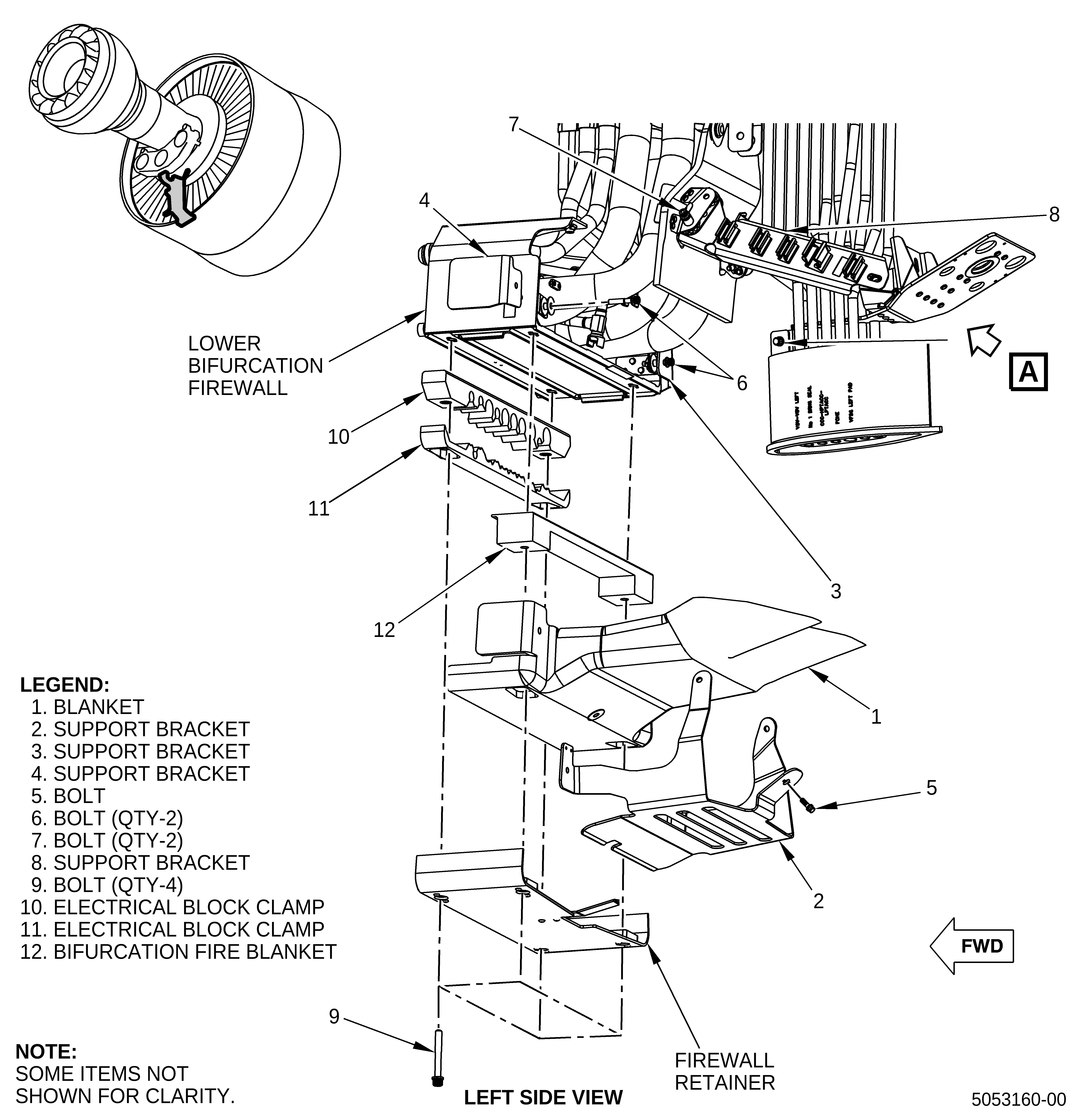
| (1) | Remove the blanket (1, Figure 1) and the support brackets (2, 3, and 4) as follows: |
| (a) | Remove the machine bolt (bolt) (5) that attaches the support bracket (2) to the blanket (1). |
| (b) | Remove the bolt (6) that attaches the support bracket (4), support bracket (2), and blanket (1) to the lower bifurcation firewall. |
| (c) | Remove the bolt (6) that attaches the support bracket (3), support bracket (2), and blanket (1) to the lower bifurcation firewall. |
| (d) | Remove the support brackets (3 and 4). |
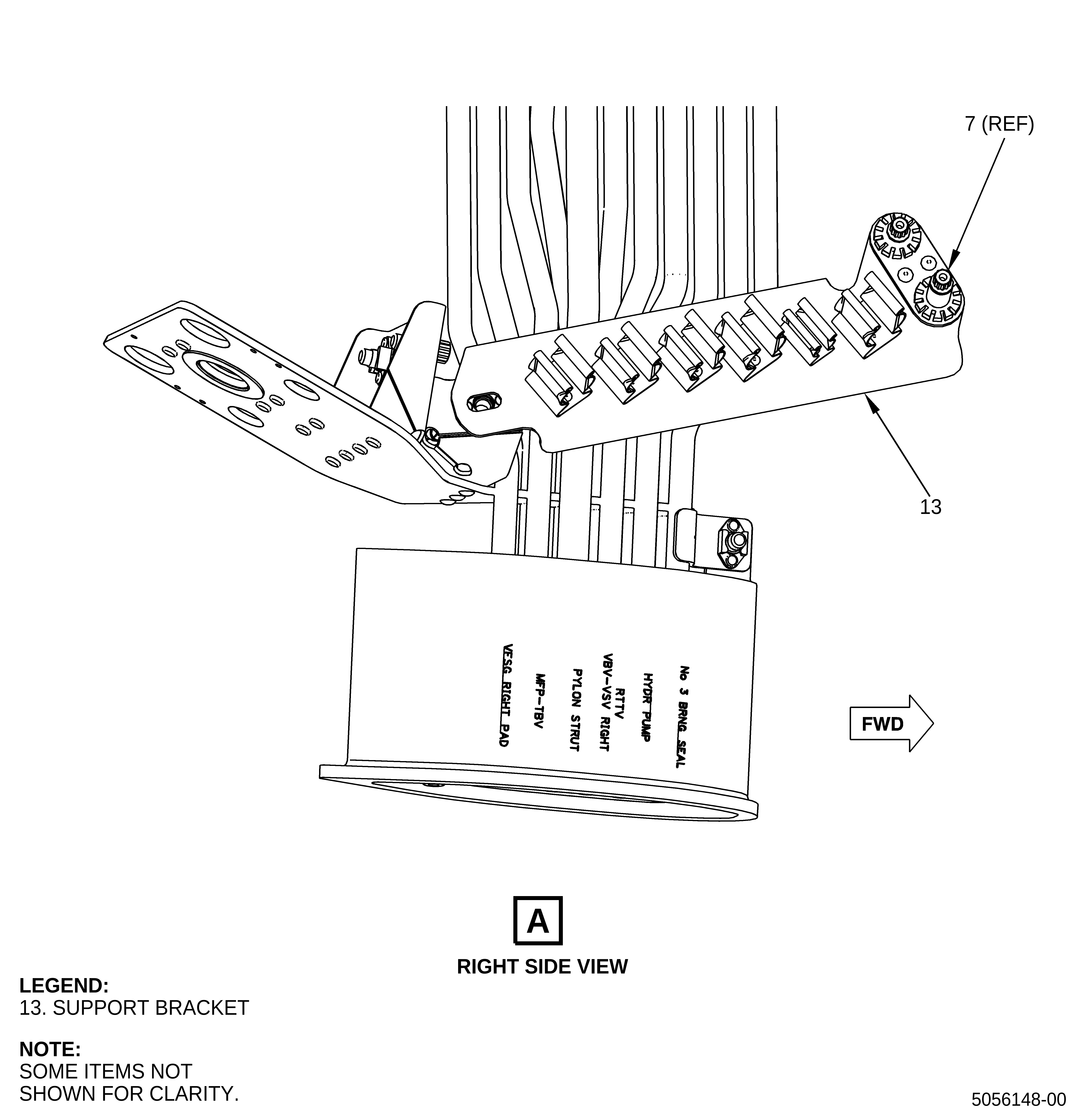
| (e) | Remove the bolt (7) that attaches the support bracket (2) and blanket (1) to the support bracket (8). |
| (f) | Remove the bolt (7) that attaches the support bracket (2) and blanket (1) to the support bracket (13). |
| (g) | Remove the support bracket (2). |
| (h) | Remove the bolts (9) that attach the firewall retainer to the lower bifurcation firewall through the electrical block clamps (10) and (11) and the bifurcation fire blanket (12) and blanket (1). |
| (i) | Remove the firewall retainer. |
| (j) | Remove the blanket (1). |
| (2) | Remove the harness W05 (1, Figure 2) and harness W13 (2) from the spring clips next to the lower bifurcation to get access to the PS25 sense tube (3). |
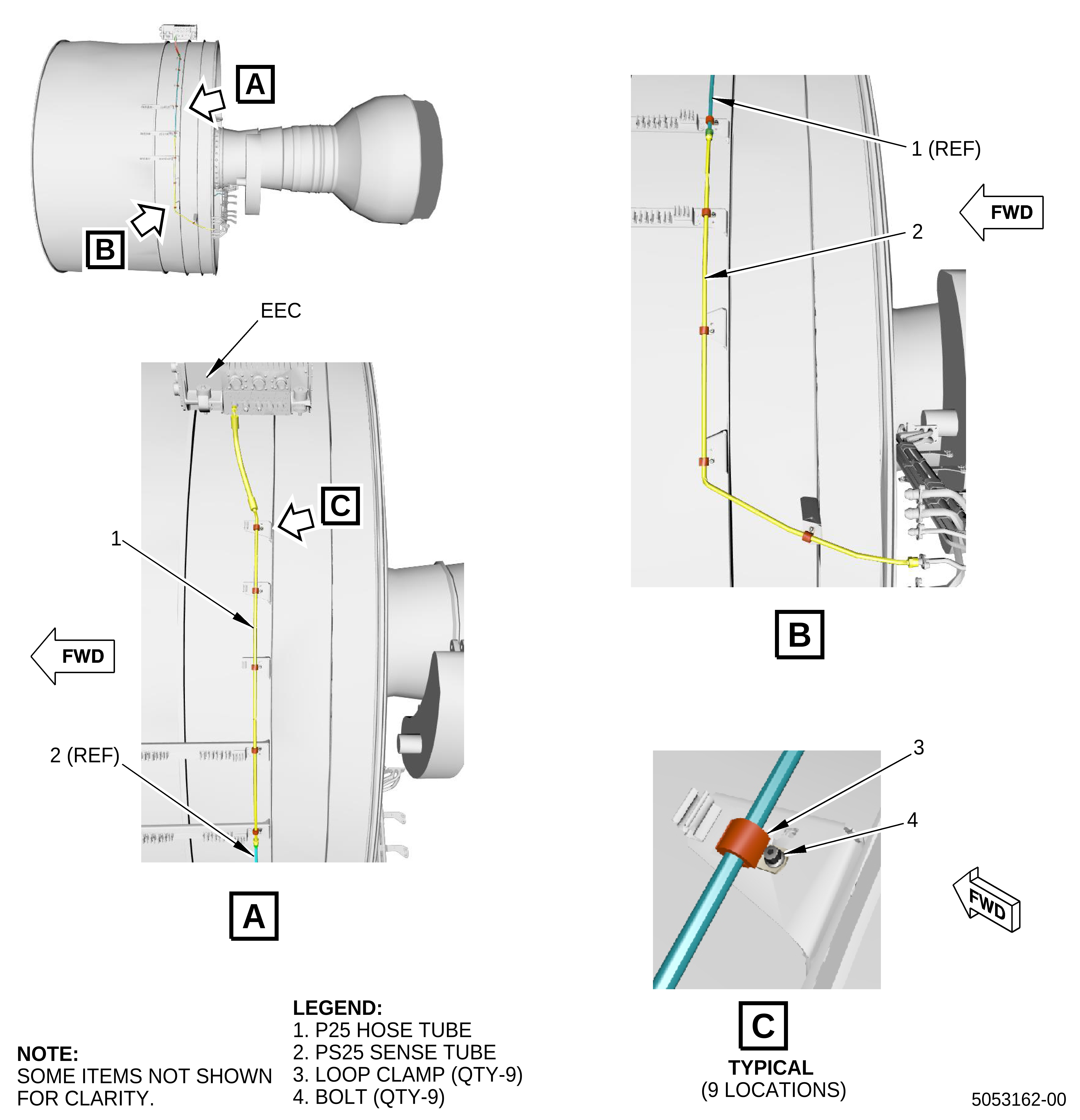
| (3) | Remove the P25 hose tube (1, Figure 3) as follows: |
| (a) | Disconnect the P25 hose tube (1) from the pressure sense fitting on the EEC. |
| (b) | Disconnect the P25 hose tube (1) from the PS25 sense tube (2). |
| (c) | Remove the five bolts (4) from the five loop clamps (3). |
| (d) | Remove the P25 hose tube (1) from the fan stator module assembly. |
| (4) | Remove the PS25 sense tube (2) as follows: |
| (a) | Remove and discard C10-145 safety cable from the PS25 sense tube (2) B-nut. |
| (b) | Disconnect the PS25 sense tube (2) B-nut from the lower bifurcation assembly. |
| (c) | Remove the four bolts (4) from the four loop clamps (3). |
| (d) | Remove the PS25 sense tube (2) from the fan stator module assembly. |
| D. | On-Wing Installation |
| (1) | Install the bifurcation fire blanket (12, Figure 1), blanket (1), and support brackets (2, 3, and 4) as follows: |
| WARNING: |
|
| (a) | Apply C02-058 lubricant or C02-023 engine oil to the threads of the bolts (5, 6, 7, and 9). |
| (b) | Put the blanket (1) onto the bifurcation fire blanket (12). |
| (c) | Tighten the bifurcation fire blanket (12) around the electrical harnesses and firmly attach it with C10-071 safety wire or C10-143 safety cable. |
| (d) | Put the support bracket (2) on the blanket (1). |
| (e) | Install the bolt (5) and torque it to 32 to 38 lb in. (3.6 to 4.2 Nm). |
| (f) | Attach the blanket (1) and support bracket (2) with the support bracket (3) on the left side forward looking aft (FLA) and the support bracket (4) on the right side FLA and install them on the lower bifurcation firewall with bolts (6). Tighten the bolts (6) with your hands. |
| (g) | Attach the support bracket (2) to the support bracket (8) on the left side aft looking forward (ALF) and to the support bracket (13) on the right side ALF with bolts (7). Tighten the bolts (7) with your hands. |
| (h) | Tighten the bolts (6) and (7) to 32 to 38 lb in. (3.6 to 4.2 Nm). |
| (i) | Install the firewall retainer onto the electrical block clamp (11) and blanket (1). |
| (j) | Install the bolts (9) and tighten them to 106 to 124 lb in. (11.9 to 14.0 Nm). |
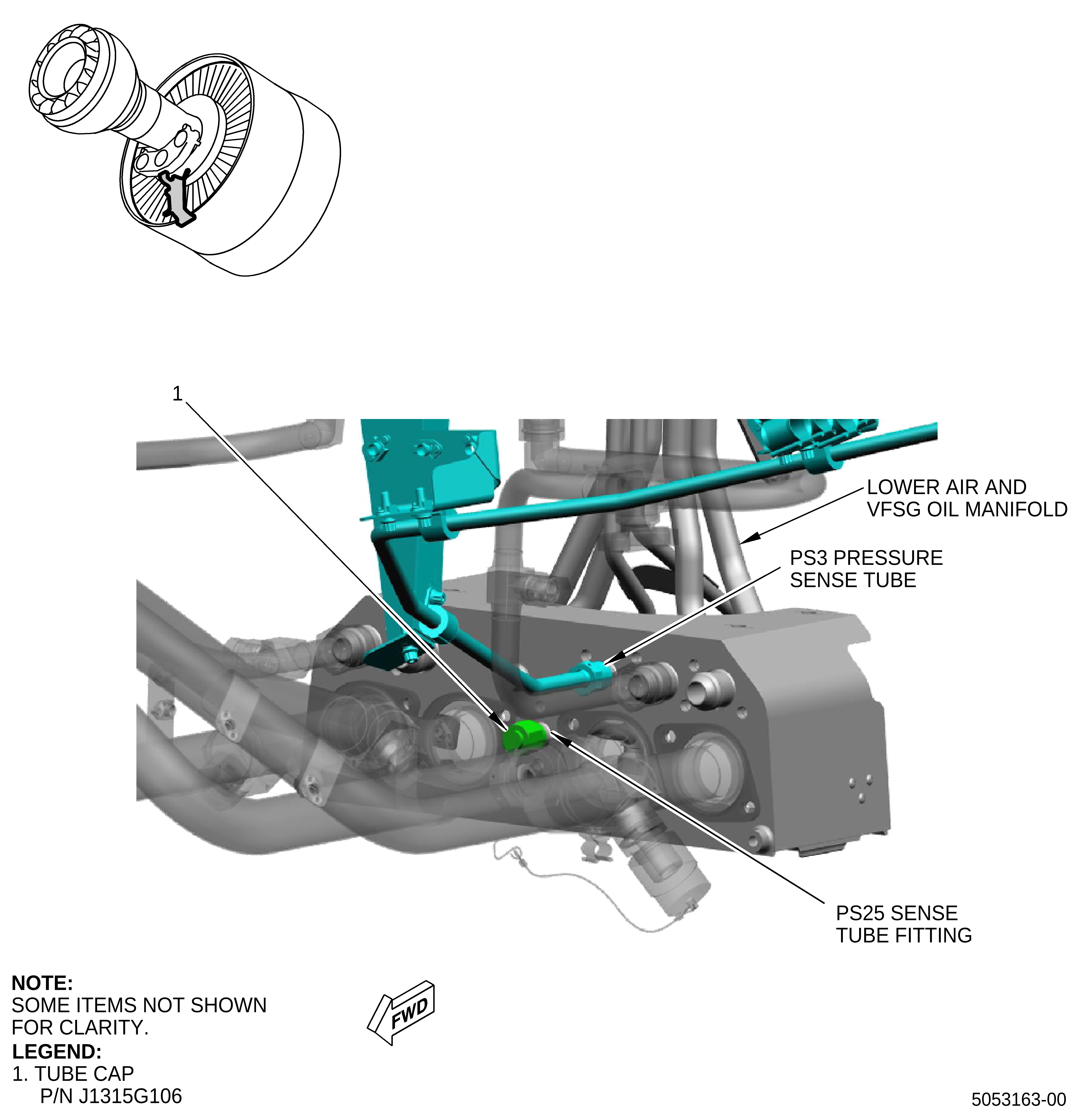
| (2) | Install the new tube cap (1, Figure 4) on the PS25 sense tube fitting of the lower air and VFSG oil manifold and do as follows: |
| (a) | Tighten the tube cap (1) to 262 to 308 lb in. (29.6 to 34.7 Nm). |
| (3) | Install the bolts (4, Figure 3) on the related nine brackets and do as follows: |
| (a) | Tighten the bolts (4) to 51 to 59 lb in. (5.7 to 6.6 Nm). |
| NOTE: |
|
| NOTE: |
|
| NOTE: |
|
| (4) | Install back the harness W05 (1, Figure 2) and harness W13 (2) in the spring clips next to the lower bifurcation. |
| E. | Aircraft Return to Service |
| (1) | Do these tasks in sequence to close the left and right thrust reversers on the applicable engine as follows: |
| (a) | Remove the protective covers P/N SPL-13475 from the left and right VFSG air/oil heat exchangers. |
| (b) | Remove the protective cover P/N SPL-13475 from the ACOC. |
| (c) | For the applicable engine, close the left and right thrust reversers. Refer to the GEnx-1B, Boeing 787 AMM, G78-31-00, Thrust Reverser (Task Selection) - Close after Access, DMC-B787-A-G78-31-00-15B-740A-A and do as follows: |
| • |
|
| • |
|
| • |
|
| • |
|
| (d) | For the applicable engine, close the left and right fan cowls. Refer to the GEnx-1B, Boeing 787 AMM, G71-11-04, Fan Cowl (Task Selection) - Close after Access, DMC-B787-A-G71-11-04-00B-740A-A and do as follows: |
| • |
|
| • |
|
| • |
|
| • |
|
| (e) | Do the thrust reverser activation. Refer to the GEnx-1B, Boeing 787 AMM, G78-31-00, Thrust Reverser (after Ground Maintenance) - Activation, DMC-B787-A-G78-31-00-15G-730B-A. |
| (f) | Do the leading edge slat system activation. Refer to the GEnx-1B, Boeing 787 AMM, 27-81-00, Leading Edge Slat System - Activation, DMC-B787-A-27-81-00-24A-730B-A. |
| (g) | Do these steps to remove the DO-NOT-OPERATE tags from the applicable ENGINE START switch and the FUEL CONTROL switch: |
| 1 | On the pilot's overhead panel, P5, remove the DO-NOT-OPERATE tag from the applicable ENGINE START switch. |
| 2 | On the pilot's aisle control stand, P10, remove the DO-NOT-OPERATE tag from the applicable FUEL CONTROL switch. |
| 3 | Do the tests of the engine control electrical harnesses shown in the power plant test reference table. Refer to the GEnx-1B, Boeing 787 AMM, G71-00-00, Power Plant Test Reference Table - Standard Practices, DMC-B787-A-G71-00-00-09A-950A-A. |
| F. | In-Shop Removal |
| (1) | Remove the P25 hose tube (1, Figure 3), PS25 sense tube (2), and loop clamps (3). Removal instructions have not changed. Refer to the GEnx-1B EM, 72-00-01, DISASSEMBLY 001, Subtask 72-00-01-040-079. |
| G. | In-Shop Installation |
| (1) | Install the new tube cap (1, Figure 4) on the PS25 sense tube fitting of the lower air and VFSG oil manifold and do as follows: |
| (a) | Tighten the tube cap (1) to 262 to 308 lb in. (29.6 to 34.7 Nm). |
| (2) | Install the bolts (4, Figure 3) on the related nine brackets and do as follows: |
| (a) | Tighten the bolts (4) to 51 to 59 lb in. (5.7 to 6.6 Nm). |
| NOTE: |
|
| NOTE: |
|
| NOTE: |
|