| GEnx-1B SERVICE BULLETIN - 75-0038 R00 | Revised: 04/18/2019 | |
| SB 75-0038 R00 AIR - Air Cooling Ducts (75-23-10) - Introduction of New Exciter Cooling System | Issued: 04/18/2019 | |
| GEnx-1B SERVICE BULLETIN - 75-0038 R00 | Revised: 04/18/2019 | |
| SB 75-0038 R00 AIR - Air Cooling Ducts (75-23-10) - Introduction of New Exciter Cooling System | Issued: 04/18/2019 | |
| GE Designated: -CONFIDENTIAL- | |
| The information contained in this document is GE proprietary information and is disclosed in confidence. It is the property of GE and shall not be used, disclosed to others or reproduced without the express written consent of GE, including, but without limitation, it is not to be used in the creation, manufacture, development, or derivation of any repairs, modifications, spare parts, designs, or configuration changes or to obtain FAA or any other government or regulatory approval to do so. If consent is given for reproduction in whole or in part, this notice and the notice set forth on each page of this document shall appear in any such reproduction in whole or part. | |
| This technical data is considered subject to the Export Administration Regulations (EAR) pursuant to 15 CFR Parts 730-774. Transfer of this data by any means to a Non-U.S. Person, whether in the United States or abroad, without the proper U.S. Government authorization (e.g., License, exemption, NLR, etc.), is strictly prohibited. | |
| Copyright (2019) General Electric Company, U.S.A. |
| 1. | PLANNING INFORMATION |
| A. | Effectivity |
| * * * FOR GEnx-1B64, -1B64/P1, -1B64/P2, -1B67, -1B67/P1, -1B67/P2, -1B70, -1B70/75/P1, -1B70/75/P2, -1B70/P1, -1B70/P2, -1B70C/P1, -1B70C/P2, -1B74/75/P1, -1B74/75/P2, -1B76A/P2 |
| This Service Bulletin is applicable to all GEnx-1B engines. |
| The exciter cooling manifold P/N 2343M34G01 and flexible joint P/N 1680M79P11 are affected by this Service Bulletin. |
| B. | Description |
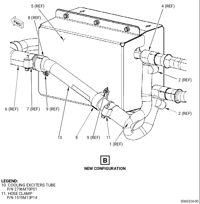
| This Service Bulletin introduces a new rubber exciter cooling air tube P/N 2775M96P01, cooling exciters tube P/N 2796M70P01, and hose clamp P/N 1519M13P14. |
| C. | Compliance |
| Category 7 |
| GE recommends that you do this Service Bulletin at customer's option. |
| Impact E |
| This recommendation is to improve the cost of ownership, reduce maintenance requirements or is a product improvement. |
| NOTE: |
|
| D. | Concurrent Requirements |
| None. |
| E. | Reason |
| (1) | Objective: |
| To introduce new parts and improve maintainability. |
| (2) | Condition: |
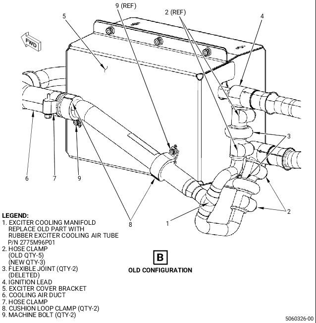
| The current configuration is conformed by the exciter cooling manifold, two rubber flexible joints, and five hose clamps that attach the components, causing an increased maintenance time. |
| (3) | Cause: |
| The new design will reduce the maintenance time by reducing the number of involved parts in the exciter cooling manifold system. |
| (4) | Improvement: |
| The new configuration will have a simplified installation, reducing the number of assembly operations. |
| (5) | Substantiation: |
| Substantiation is by analysis and comparative analysis. |
| F. | Approval |
| The data contained in this Service Bulletin has been reviewed by the FAA or authorized entity representing the FAA and the repair(s) and modification(s) herein comply with the applicable Aviation Regulations and are APPROVED for installation in the model(s) listed in this Service Bulletin. |
| G. | Manpower |
| An estimate of the labor cost to accomplish this Service Bulletin may be obtained from any GEnx-1B GE Aviation authorized Service or Overhaul facility upon request. |
| H. | Weight and Balance |
| Weight and balance are not changed. |
| I. | References (Use the latest version of these documents) |
| GEnx-1B, Boeing 787 Aircraft Maintenance Manual (AMM) |
| GEK 112851, GEnx-1B Engine Manual (EM) |
| GEK 112864, GEnx-1B Engine Illustrated Parts Catalog (EIPC) |
| NOTE: |
|
| J. | Publications Affected |
| GEnx-1B, Boeing 787 Aircraft Maintenance Manual (AMM) |
| GEK 112851, GEnx-1B Engine Manual (EM) |
| GEK 112864, GEnx-1B Engine Illustrated Parts Catalog (EIPC) |
| K. | Interchangeability |
| Qualified interchangeability. |
| The old configuration is one-way interchangeable as a full set with the new configuration. Interchangeability at the piece-part level is not permitted. |
| L. | Software Accomplishment Summary |
| Not applicable. |
| 2. | MATERIAL INFORMATION |
| A. | Material - Price and Availability |
| (1) | Parts necessary to do this Service Bulletin: |
|
| NOTE: |
|
| (2) | Other Spare Parts: |
| None. |
| (3) | Consumables: |
| None. |
| B. | Industry Support Information |
| None. |
| C. | Configuration Chart |
|
| Operation Codes AD=Add DE=Delete QTC=Quantity Change RE=Replace RM=Remains |
| Change Codes 5=Qualified interchangeability. Refer to paragraph 1.K., Interchangeability. |
| Support Codes B=Old parts will be supplied until all old parts are sold. E=Old parts will be supplied, and can be used at other engine locations. |
| D. | Parts Disposition |
| Use serviceable old parts at other engine locations. |
| Discard old parts. |
| E. | Tooling - Price and Availability |
| None. |
| 3. | ACCOMPLISHMENT INSTRUCTIONS |
| A. | In-Shop Instructions |
| (1) | Remove the old configuration as follows: |
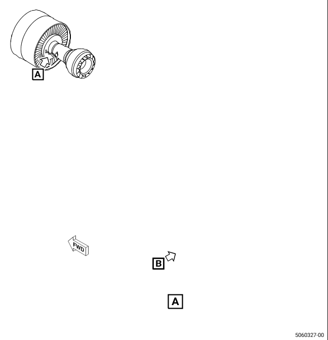
| (a) | Remove the exciter cooling manifold (1, Figure 1). Refer to the GEnx-1B EM, 72-00-02, DISASSEMBLY 002, CONFIG 01, Subtask 72-00-02-030-401 or CONFIG 02, Subtask 72-00-02-030-560. |
| (2) | Install the new configuration as follows: |
| (a) | Remove the protective covers from the rubber exciter cooling air tube (1, Figure 1) and cooling exciters tube (10). |
| (b) | Install the rubber exciter cooling air tube (1) at each of the ignition leads (4). |
| (c) | Attach the rubber exciter cooling air tube (1) to the ignition lead (4) with the hose clamps (2). Install the hose clamps (2) with the bolt assembly aft and the head outboard. |
| (d) | Install the forward end of the cooling exciters tube (10) in the cooling air duct (6). |
| (e) | Install the aft end of the cooling exciters tube (10) in the rubber exciter cooling air tube (1). |
| (f) | Attach the forward end of the cooling exciters tube (10) to the cooling air duct (6) with the hose clamp (7). Install the hose clamp (7) with the bolt assembly outboard and the head down. |
| (g) | Attach the aft end of the cooling exciters tube (10) to the rubber exciter cooling air tube (1) with the hose clamp (11). Install the hose clamp (11) with the bolt assembly outboard and the head down. |
| (h) | Attach the cooling exciters tube (10) to the exciter cover bracket (5) with the cushion loop clamps (8) and machine bolts (9). |
| (i) | Torque the hose clamps (2, 7, and 11) to 32 to 38 lb in. (3.6 to 4.2 Nm). |
| (j) | Torque the machine bolts (9) to 32 to 38 lb in. (3.6 to 4.2 Nm). |
| B. | On-Wing Instructions |
| (1) | Remove the old configuration as follows: |
| (a) | Remove the exciter cooling manifold (1, Figure 1). Refer to the GEnx-1B Boeing 787 AMM, G74-11-01, Removal DMC-B787-A-G74-11-01-00A-520A-A. |
| (2) | Install the new configuration as follows: |
| (a) | Remove the protective covers from the rubber exciter cooling air tube (1, Figure 1) and cooling exciters tube (10). |
| (b) | Put the rubber exciter cooling air tube (1) into its position and connect the rubber exciter cooling air tube (1) to the cooling exciters tube (10) with the hose clamp (11). Do not tighten the hose clamp (11) at this time. |
| (c) | Put the rubber exciter cooling air tube (1) and the cooling exciters tube (10) into its position and connect the cooling exciters tube (10) to the cooling air duct (6) with the hose clamp (7). Do not tighten the hose clamp (7) at this time. |
| (d) | Install the cushion loop clamps (8) to attach the cooling exciters tube (10) to the exciter cover bracket (5) with the two machine bolts (9). Do not tighten the machine bolts (9) at this time. |
| (e) | Install the hose clamps (2) to attach the rubber exciter cooling air tube (1) to the ignition lead (4). Do not tighten the hose clamps (2) at this time. |
| (f) | Torque the hose clamps (2, 7, and 11) to 32 to 38 lb in. (3.6 to 4.2 Nm). |
| (g) | Torque the two machine bolts (9) to 32 to 38 lb in. (3.6 to 4.2 Nm). |
| (3) | Return the aircraft back to its usual condition. Refer to the GEnx-1B Boeing 787 AMM, G74-11-01, Installation DMC-B787-A-G74-11-01-00A-720A-A. |