| GEnx-1B SERVICE BULLETIN - 79-0014 R03 | Revised: 06/30/2015 | |
| SB 79-0014 R03 OIL SYSTEM - VFSG Oil Tubes-Fill and Overfill (79-22-10) - VFSG Oil Tubes and Steel Heat Shields Release | Issued: 11/26/2012 | |
| GEnx-1B SERVICE BULLETIN - 79-0014 R03 | Revised: 06/30/2015 | |
| SB 79-0014 R03 OIL SYSTEM - VFSG Oil Tubes-Fill and Overfill (79-22-10) - VFSG Oil Tubes and Steel Heat Shields Release | Issued: 11/26/2012 | |
| GE PROPRIETARY INFORMATION | |
| The information contained in this document is GE proprietary information and is disclosed in confidence. It is the property of GE and shall not be used, disclosed to others or reproduced without the express written consent of GE, including, but without limitation, it is not to be used in the creation, manufacture, development, or derivation of any repairs, modifications, spare parts, designs, or configuration changes or to obtain FAA or any other government or regulatory approval to do so. If consent is given for reproduction in whole or in part, this notice and the notice set forth on each page of this document shall appear in any such reproduction in whole or in part. | |
| This technical data is considered EAR controlled pursuant to 15 CFR Parts 730-774 respectively. Transfer of this data by any means to a Non-US Person, whether in the United States or abroad, without the proper U.S. Government authorization (e.g., License, exemption, NLR, etc.), is strictly prohibited. | |
| Copyright (2015) General Electric Company, U.S.A. |
| TRANSMITTAL INFORMATION |
| REVISION 3 TO SERVICE BULLETIN 79-0014 |
| Revision 3 is issued to update paragraphs 1.I., References , 1.K., Interchangeability , and 2.A., Material - Price and Availability . |
| Revision 2 was issued August 28, 2013. Revision 1 was issued June 28, 2013. The original was issued November 26, 2012. Revision bars in the left margin identify changes. |
| 1. | PLANNING INFORMATION |
| A. | Effectivity |
|
| This Service Bulletin has been introduced in production to these GEnx-1B engines: |
| • |
|
| These serial numbers are the best available data. |
| The variable frequency starter generators (VFSG) oil tubes P/N ER5116G01, P/N ER4259G01, P/N ER4265G01, P/N ER4448G01, P/N ER4447G01, P/N ER3731G01, P/N ER6013G01, and heat shields P/N 2343M77G02, P/N 2316M28G02, P/N 2380M67G01, P/N 2409M79G01, P/N 2316M33P01, P/N 2328M53G02, P/N 2344M99G02, and P/N 2379M52G01 are affected by this Service Bulletin. |
| B. | Description |
| This Service Bulletin releases the optimized VFSG cooling system on the core replacing the tube hose assemblies P/N ER5762P01, P/N ER6002G01, P/N ER6003G01, P/N ER5734G01, P/N ER5759G01, P/N ER5736G01, P/N ER6004G01, P/N ER5738G01, P/N ER5737G01, P/N ER5739G01, P/N ER5763G01, and the stainless steel heat shield P/N 2403M47G01, P/N 2403M48G01, P/N 2403M49G01, P/N 2403M52G01, P/N 2403M61P01, and P/N 2403M62G01. |
| C. | Compliance |
| Category 6 |
| GE recommends that you do this Service Bulletin when the VFSG oil tubes and heat shields are routed for repair. |
| NOTE: |
|
| This Service Bulletin is offered to improve the reliability or performance of your GE product, or to help prevent the occurrence of the event or condition described in this Service Bulletin. If the operator elects not to participate in the bulletin, that decision will be taken into consideration by GE in evaluating future product performance issues that may arise in the operators fleet. |
| D. | Concurrent Requirements |
| None. |
| E. | Reason |
| (1) | Objective: |
| To introduce new parts, improve reliability, and improve maintainability. |
| (2) | Condition: |
| The current VFSG cooling system uses two hoses per generator, causing difficulty to remove the fuel nozzle because of a clamp point on the aft skirt. In addition, the heat shield design costs more than the target for the component. |
| (3) | Cause: |
| The use of hoses was accepted in without hardware attached to it prior to the removal. This resulted in the need for hoses that could be swung away from the removal path. Also, the design of the current heat shield uses a costly process because it is made of titanium. |
| (4) | Improvement: |
| The conversion of hoses to tubes and the elimination of unnecessary support hardware result in an optimized and lighter configuration. The mounting location on the aft skirt is moved to the heat shield eliminating the fuel nozzle removal conflict and the new design of the heat shield. |
| (5) | Substantiation: |
| Substantiation is by analysis, comparative analysis, and test. |
| F. | Approval |
| This Service Bulletin has been reviewed by the FAA and the repair(s) and modification(s) herein comply with the applicable Federal Aviation Regulations and are FAA APPROVED for installation in the model(s) listed in this Service Bulletin. |
| G. | Manpower |
| No additional man-hours are required to comply with this Service Bulletin. |
| H. | Weight and Balance |
| The complete compliance with this Service Bulletin increases weight by 10.90 lb (4.94 kg). |
| I. | References (Use the latest version of these documents) |
| GEK 112851, GEnx-1B Engine Manual (EM) |
| GEK 112864, GEnx-1B Engine Illustrated Parts Catalog (EIPC) |
| NOTE: |
|
| J. | Publications Affected |
| GEK 112851, GEnx-1B Engine Manual (EM) |
| GEK 112864, GEnx-1B Engine Illustrated Parts Catalog (EIPC) |
| K. | Interchangeability |
| Qualified interchangeability. |
| For interchangeability purposes, hardware affected by SB 79-0014 is grouped as shown in Table 1. |
| Interchangeability conditions are explain by Table 2. |
|
|
| NOTE: |
|
| NOTE: |
|
| NOTE: |
|
| L. | Software Accomplishment Summary |
| Not applicable. |
| 2. | MATERIAL INFORMATION |
| A. | Material - Price and Availability |
| (1) | Parts necessary to do this Service Bulletin: |
|
| NP = Not Provisioned |
| NOTE: |
|
| *Part not supplied by GE Engine Services Distribution L.L.C. Procure through local purchase. |
| **Part not supplied by GE Engine Services Distribution L.L.C. To procure parts, contact the following: |
| Elano Corp. 2455 Dayton-Xenia Rd. Dayton, OH 45434-7199 U.S.A. |
| (2) | Other Spare Parts: |
| None. |
| (3) | Consumables: |
|
| B. | Industry Support Information |
| None. |
| C. | Configuration Chart |
|
| Operation Codes AD=Add DE=Delete RE=Replace RM=Remains RW=Rework QTC=Quantity Change |
| Change Code 5=Qualified interchangeability. Refer to paragraph 1.K., Interchangeability. |
| Support Codes A=Old parts will no longer be supplied. B=Old parts will be supplied until all old parts are sold. E=Old parts will be supplied, and can be used at other engine locations. |
| D. | Parts Disposition |
| Use serviceable old parts at other engine locations. |
| E. | Tooling - Price and Availability |
| None. |
| 3. | ACCOMPLISHMENT INSTRUCTIONS |
| A. | Removal |
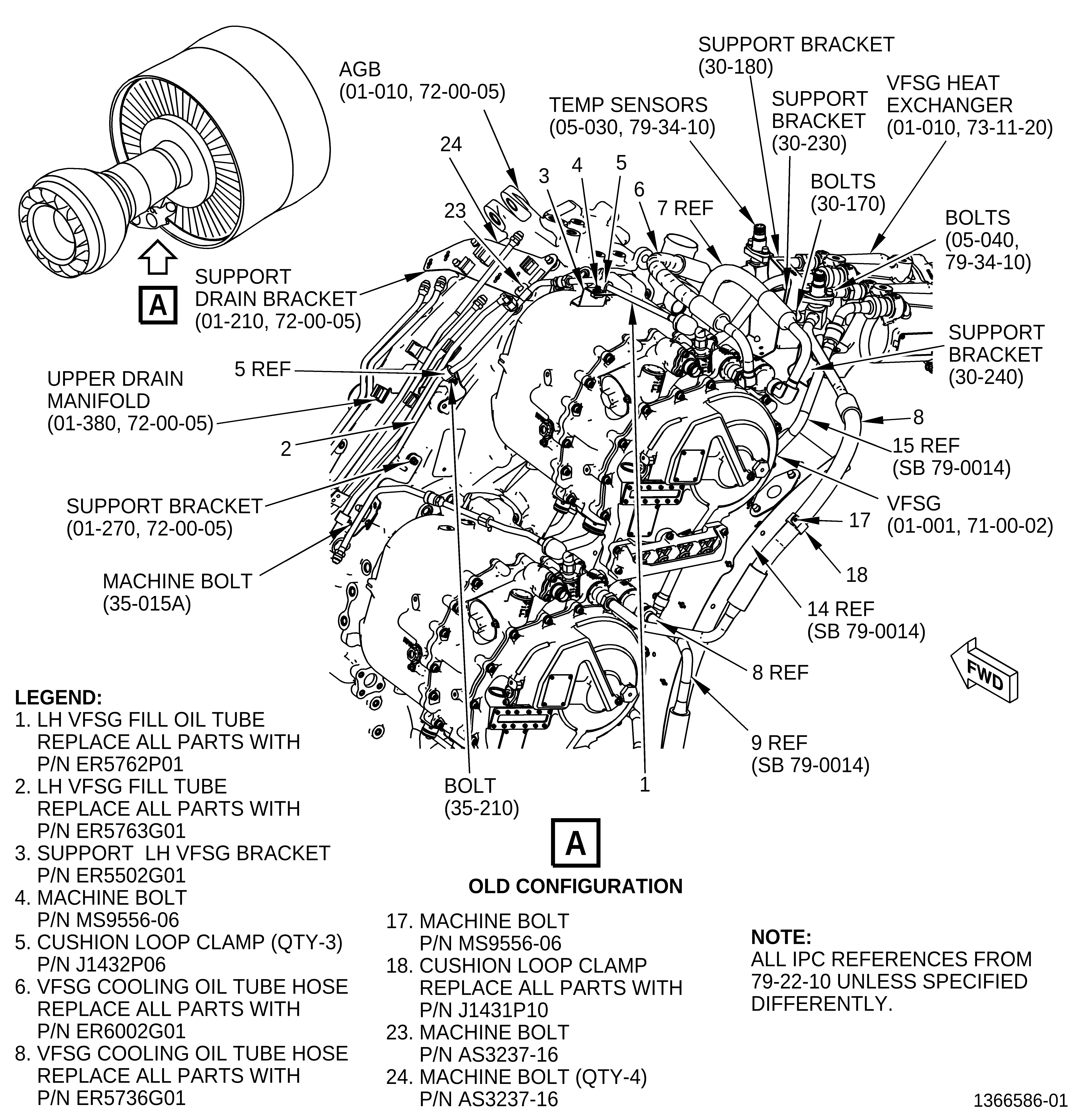
| (1) | Remove the LH VFSG fill oil tubes (1 and 2, Figure 5), support LH VFSG bracket (3), machine bolt (4), cushion loop clamp (5) , and VFSG oil tube hoses (6, 7, 8, and 9). Refer to GEnx-1B EM, 72-00-02, DISASSEMBLY 001, Subtask 72-00-02-030-471. |
| (2) | Remove the W32 (10-010, 73-21-66 ) and W33 (15-010) electrical harness from the aft skirt segment heat shields (10, 11, and 12, Figure 3). Refer to GEnx-1B EM, 72-00-02, DISASSEMBLY 001, Subtask 72-00-02-030-353. |
| (3) | Remove the OB2 power cable (65-040, 72-00-02) from the aft skirt segment modified heat shield (13). Refer to GEnx-1B EM, 72-00-02, DISASSEMBLY 001, Subtask 72-00-02-030-438. |
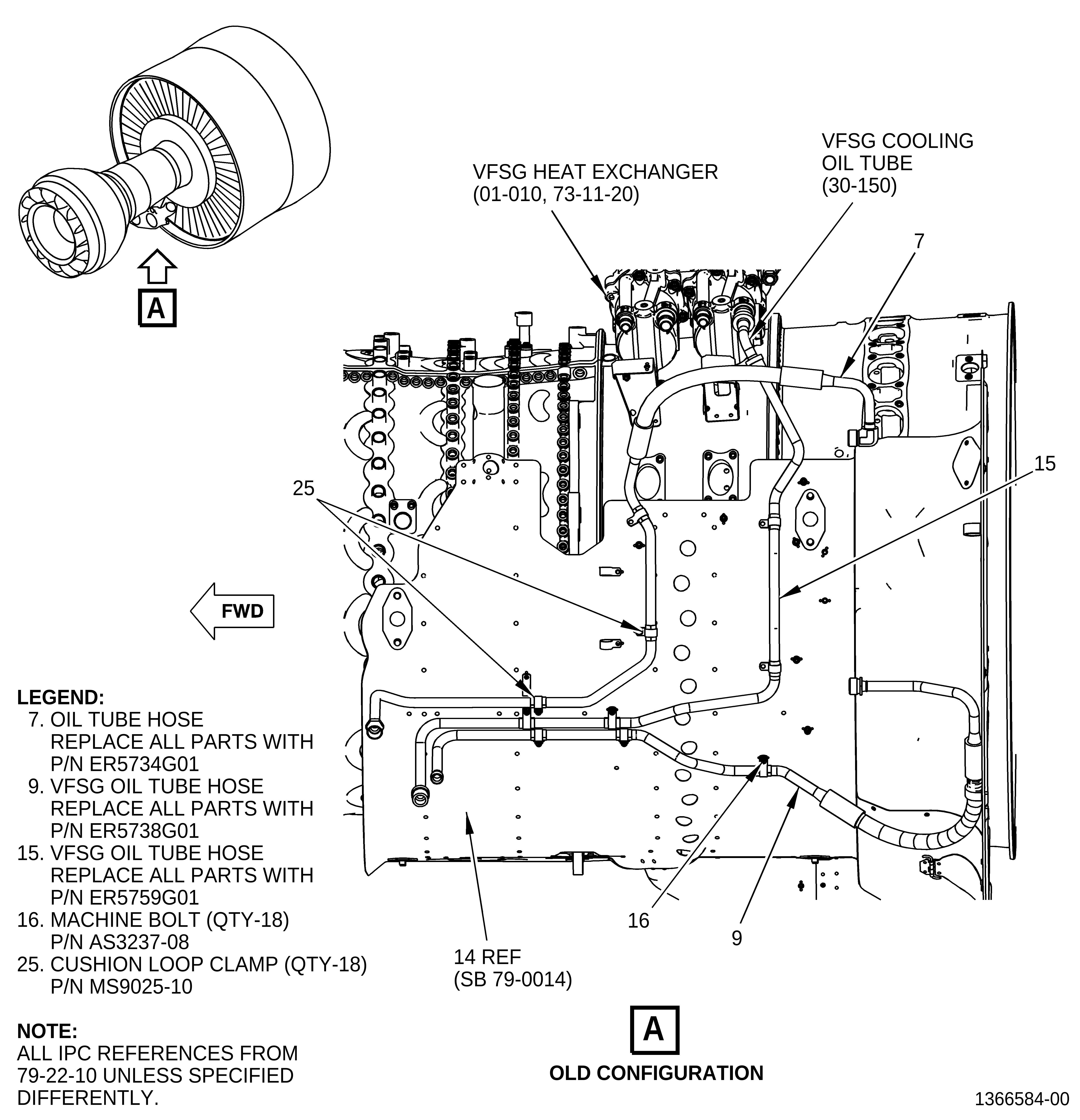
| (4) | Remove the VFSG oil tube hoses (6, 7, 8, 9, and 15, Figure 4 and Figure 5), machine bolts (16, 17), and cushion loop clamp (18). Refer to GEnx-1B EM, 72-00-02, DISASSEMBLY 002, Subtask 72-00-02-030-417. |
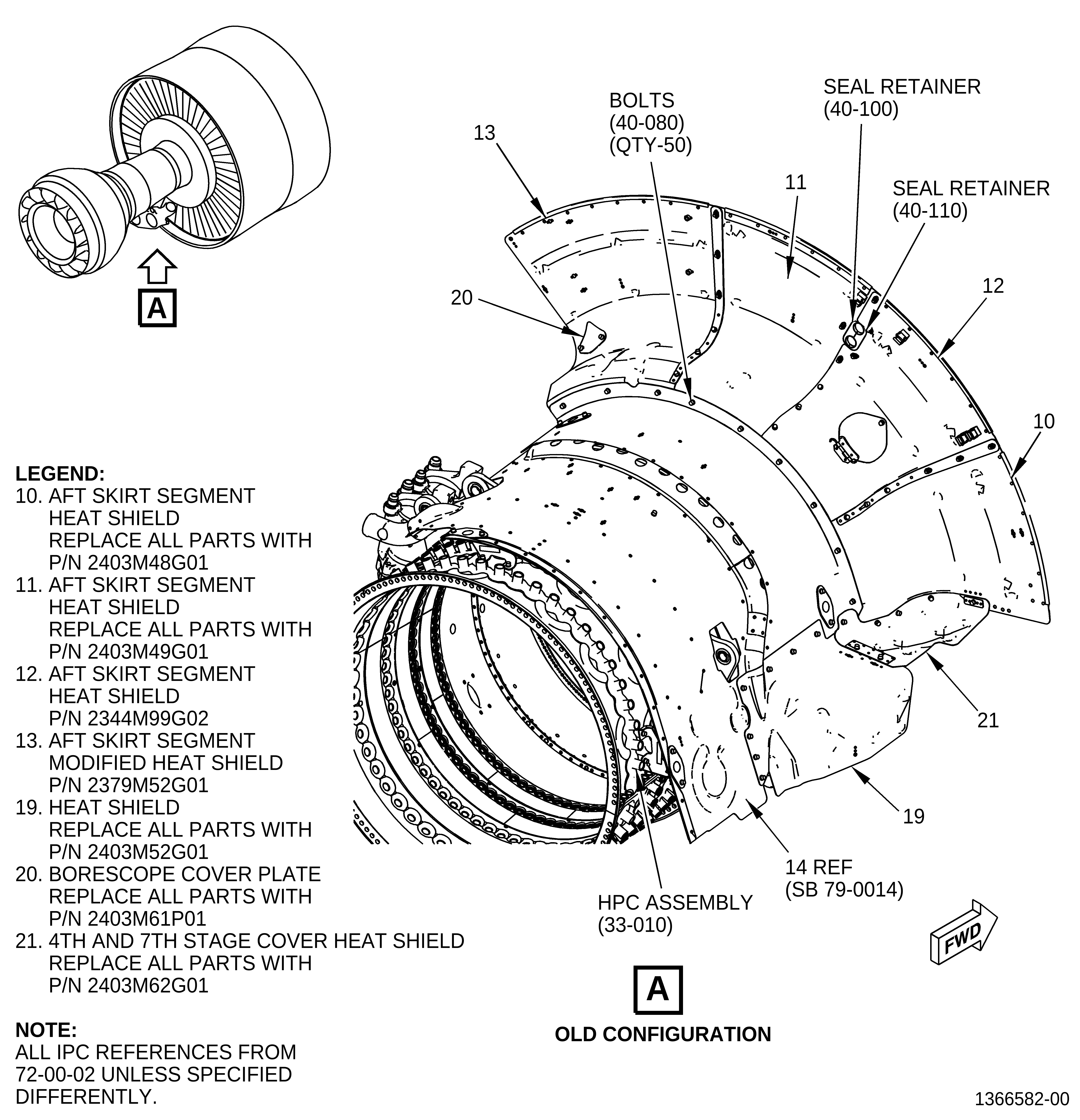
| (5) | Remove the aft skirt heat segment shields (10, 11, 12, 13, 19, 20, and 21, Figure 3). Refer to GEnx-1B EM, 72-00-02, DISASSEMBLY 003, Subtask 72-00-02-030-371. |
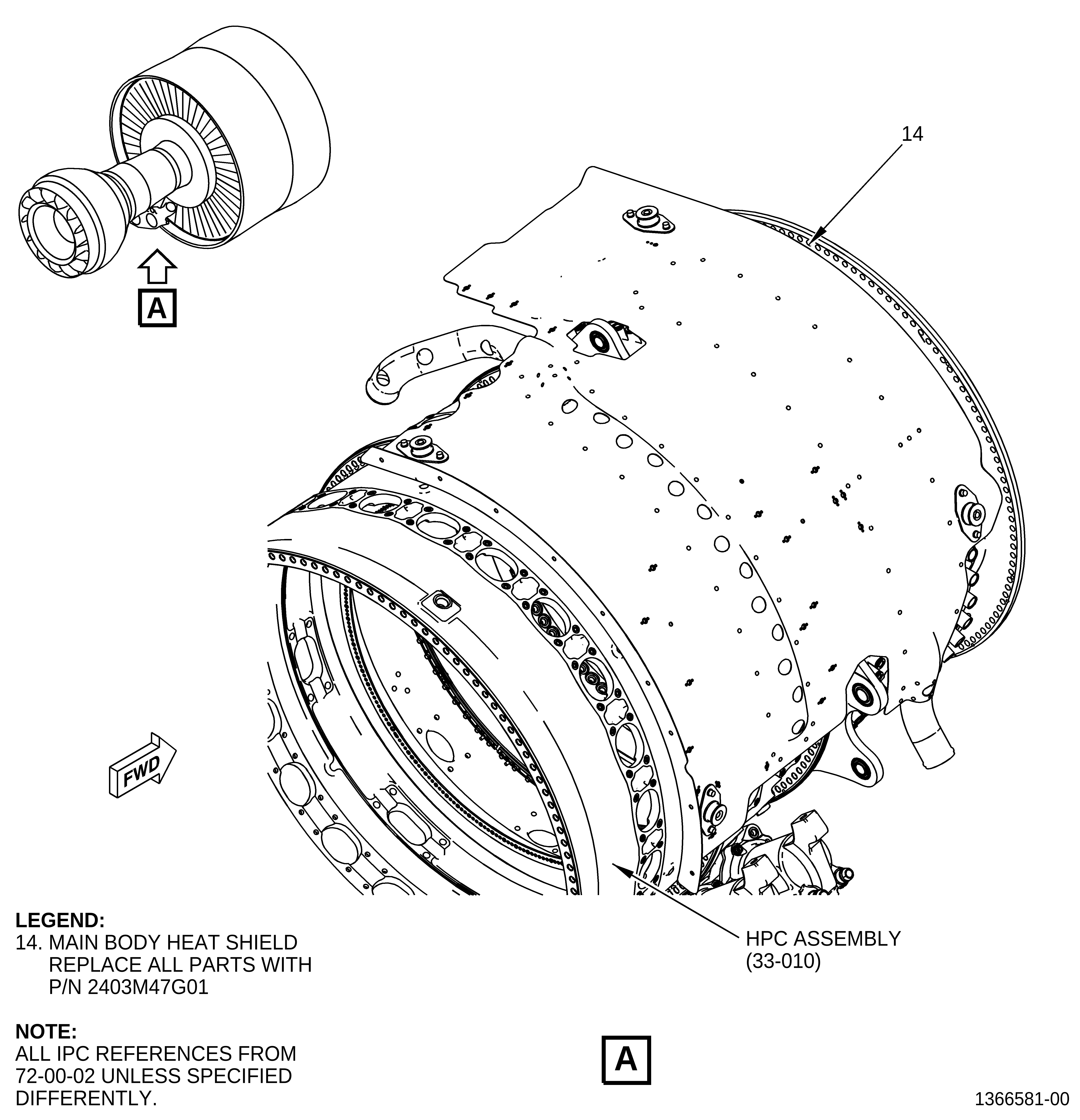
| (6) | Remove the main body heat shield (14, Figure 2). Refer to GEnx-1B EM, 72-00-02, DISASSEMBLY 003, Subtask 72-00-02-030-372. |
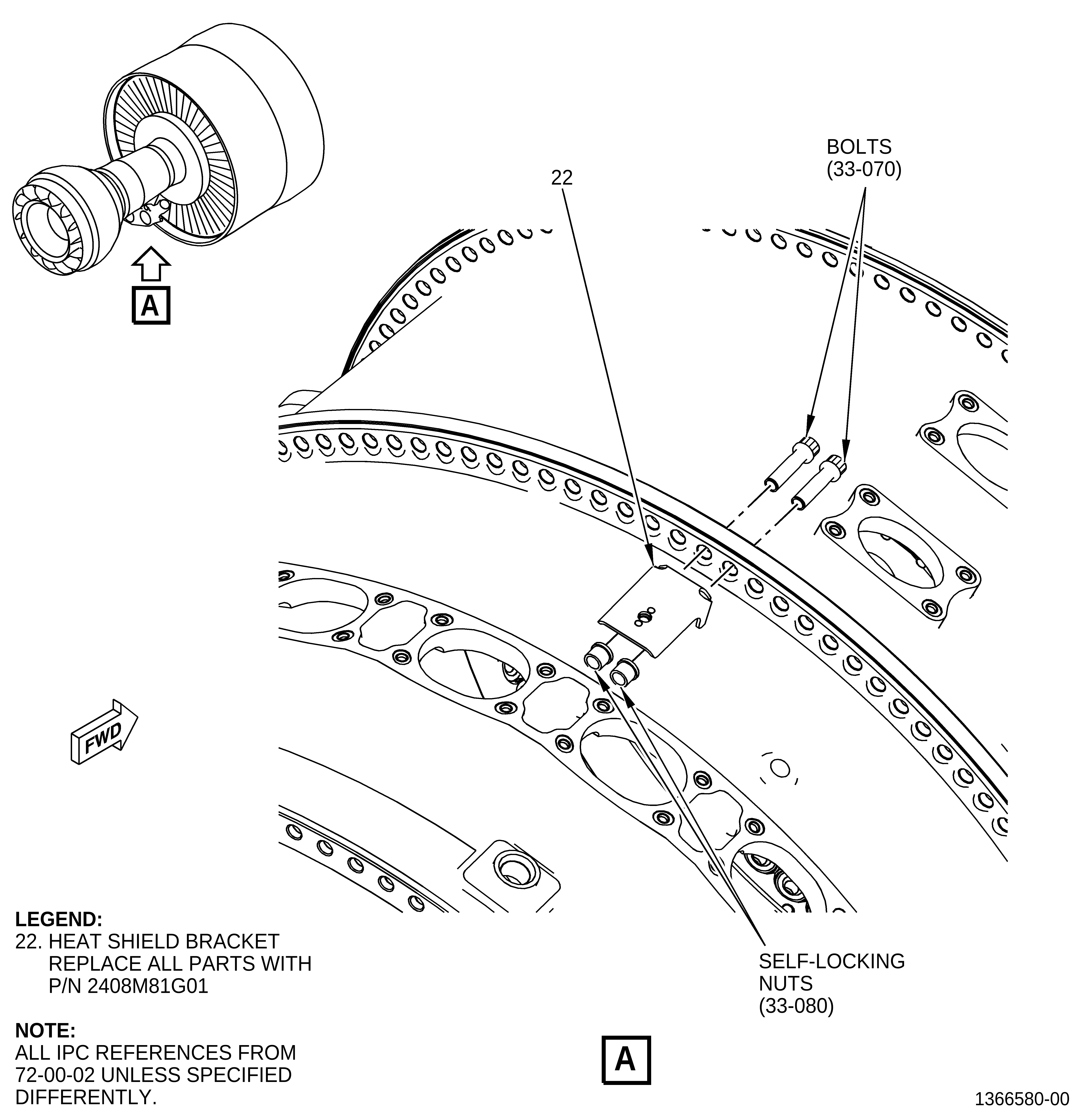
| (7) | Remove the heat shield bracket (22, Figure 1). Refer to GEnx-1B EM, 72-00-02, DISASSEMBLY 005, Subtask 72-00-02-030-493. |
| (8) | Remove the machine bolts (4, Figure 5), cushion loop clamp (5), LH VFSG fill tube (2), machine bolts (23). Refer to GEnx-1B EM, 72-00-05, DISASSEMBLY 001, Subtask 72-00-05-030-041. |
| (9) | Remove machine bolt (23). Refer to GEnx-1B EM, 72-00-05, DISASSEMBLY 001, Subtask 72-00-05-030-008. |
| B. | Installation |
| (1) | Install the heat shield bracket (22, Figure 1) in boltholes No. 83 and 84 on the aft side of the flange with bolts (33-070, 72-00-02) and self-locking nuts (33-080). Tighten the self-locking nuts by hand. |
| (2) | Install the main body heat shield (14, Figure 2) at the 6:00 o'clock position of the HPC assembly (33-010). Refer to GEnx-1B EM, 72-00-02, ASSEMBLY 004, Subtask 72-00-02-440-177. |
| (3) | Install the heat shield aft skirt segments as follows: |
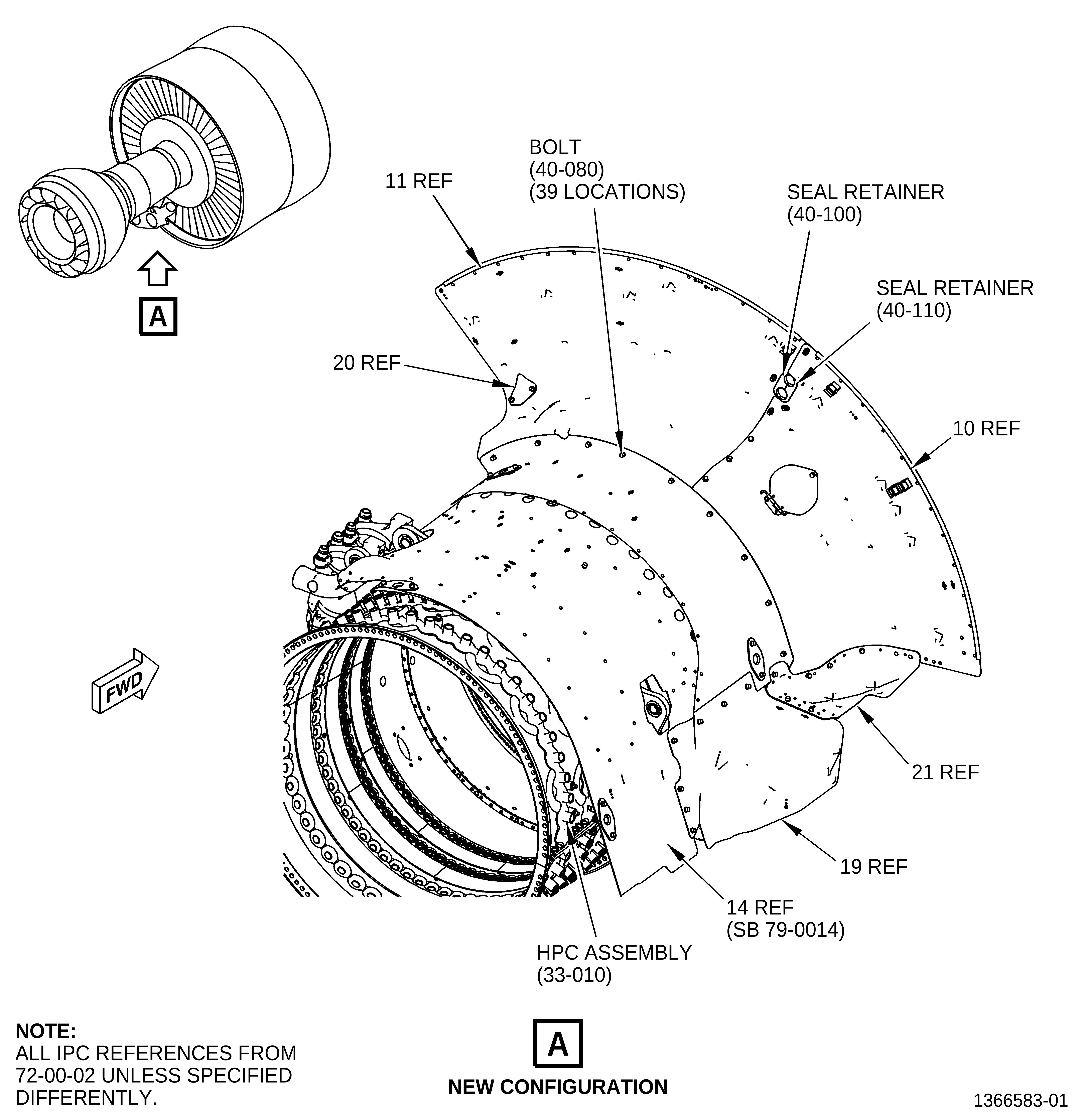
| (a) | Install the aft skirt segment heat shield (10, Figure 3) on the main body heat shield (14, Figure 2) at the 7:30 o'clock position (FLA). Attach the aft skirt segment with bolts (40-080). |
| (b) | Install the aft skirt segment heat shield (11, Figure 3) on the main body heat shield (14, Figure 2) at the 5:30 o'clock position (FLA). Attach the aft skirt segment with bolts (40-080). |
| (c) | Attach the aft skirt segment heat shield (11, Figure 3) to the aft skirt segment heat shield (10, Figure 3) with bolts (40-080). |
| (d) | Torque the bolts (40-080) to 106-124 lb in. (12.0-14.0 N.m). |
| (e) | Install the heat shield (19, Figure 3) on the main body heat shield (14, Figure 2) at the 8:30 o'clock position (FLA). Attach it with bolts (40-080). |
| (f) | Install the 4th and 7th stage cover heat shield (21, Figure 3) on the main body heat shield (14, Figure 2), heat shield (19, Figure 3), and aft skirt segment heat shield (10, Figure 3) at the 8:00 o'clock position (FLA). Attach it with bolts (40-080). |
| (g) | Torque the bolts (40-080) to 106-124 lb in. (12.0-14.0 N.m). |
| (h) | Install the borescope cover plate (20, Figure 3) on the aft skirt segment heat shield (11) with bolts (40-080). |
| (i) | Torque the bolts (40-080) to 106-124 lb in. (12.0-14.0 N.m). |
| (j) | Install the seal retainer (40-100) and seal retainer (40-110) on the aft skirt segment heat shield (11) and aft skirt segment heat shield (10) Attach with bolts (40-080). |
| (k) | Torque the bolts (40-080) to 106-124 lb in. (12.0-14.0 N.m). |
| (4) | Install VFSG oil tube hose (15, Figure 4) and VFSG cooling oil tube (30-150, 79-22-10) as follows: |
| (a) | Connect the VFSG oil tubes hose (15) to the VFSG cooling oil tube (30-150). |
| WARNING: |
|
| NOTE: |
|
| (b) | Attach the VFSG oil tube hose (15) to the main body heat shield (14) at four locations with cushion loop clamps (25) and machine bolts (16). |
| (c) | Torque the B-nut of the VFSG oil tube (30-150) at the VFSG oil tube hose (15) to 55-65 lb ft (75-88 N.m). |
| (d) | Torque the machine bolts (16) to 60-70 lb in. (6.8-7.9 N.m). |
| (e) | Install the VFSG cooling oil tube (oil tube) (30-160) and VFSG oil tube (oil tube) (30-100). Refer to the GEnx-1B EM, 72-00-02, ASSEMBLY 005, Subtask 72-00-02-440-184. |
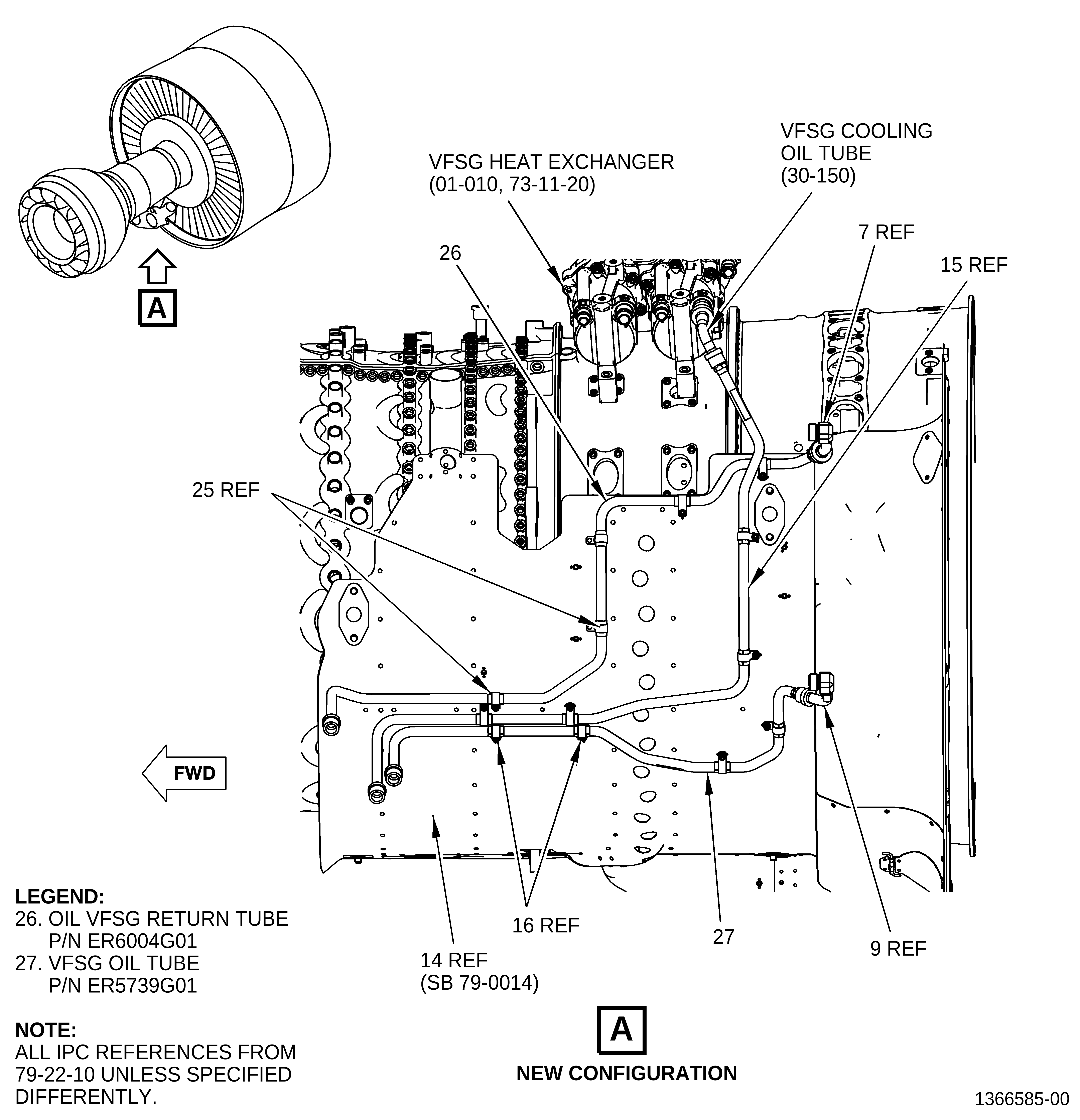
| (5) | Install the oil tube hose (7), oil VFSG return tube (26), VFSG oil tube hose (9), and VFSG oil tube (27) as follows: |
| (a) | Attach the oil VFSG return tube (26) to the main body heat shield (14) at five locations with cushioned loop clamps (25) and machine bolts (16). |
| (b) | Attach the VFSG oil tube (27) to the main body heat shield (14) at five locations with cushioned loop clamps (25) and machine bolts (16). |
| (c) | Torque the bolts (16) to 60-70 lb in. (6.8-7.9 N.m). |
| (d) | Attach the oil tube hose (7) to the oil VFSG return tube (26). |
| (e) | Torque the B-nut of the oil tube hose (7) at the oil VFSG return tube (26) to 55-65 lb ft (75-88 N.m). |
| (f) | Attach the VFSG oil tube hose (9) to the VFSG oil tube (27). |
| (g) | Torque the B-nut of the VFSG oil tube hose (9) at the VFSG oil tube (27) to 55-65 lb ft (75-88 N.m). |
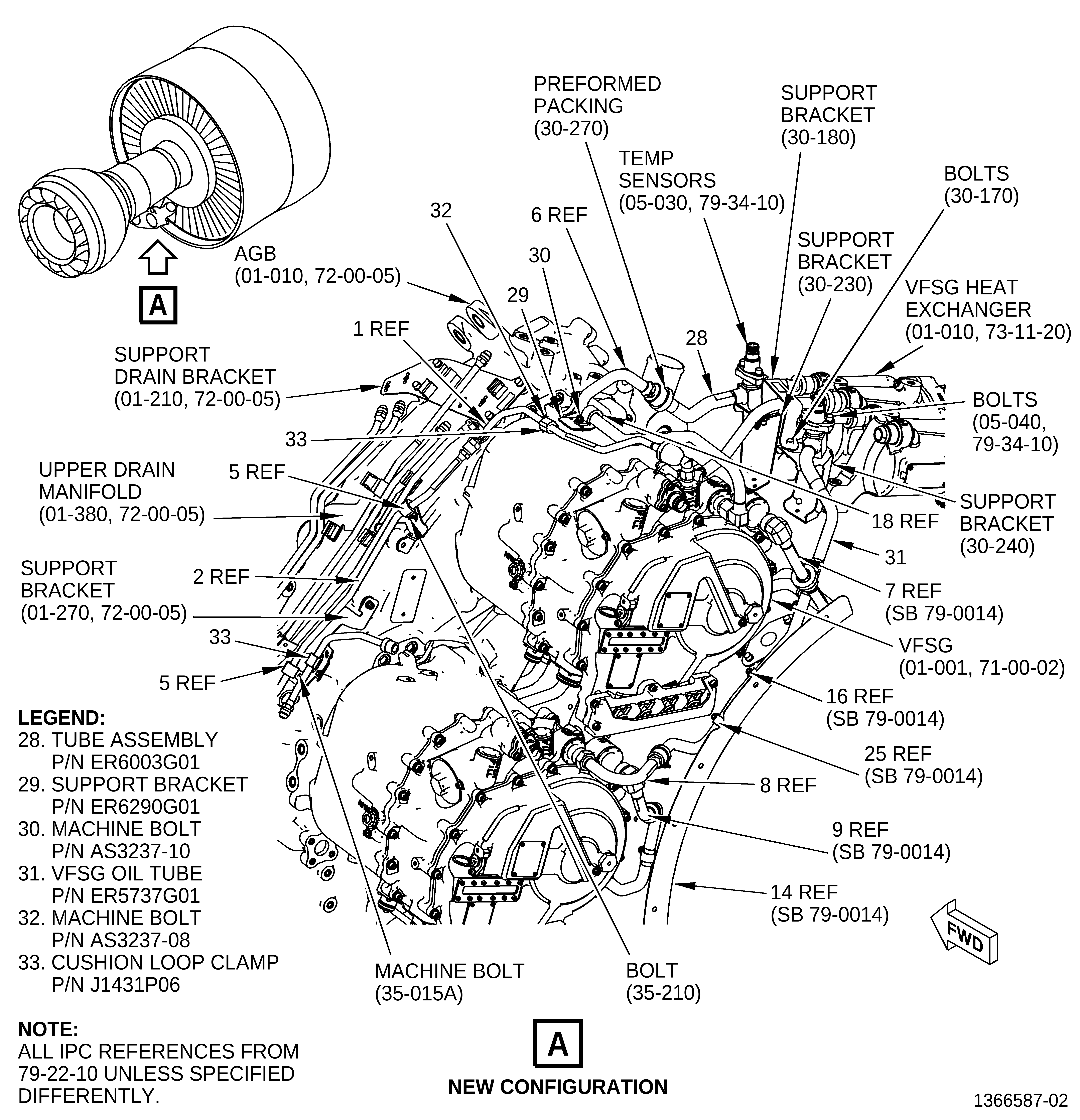
| (6) | Install the VFSG cooling oil tube hose (6, Figure 5), tube assembly (28), VFSG cooling oil tube hose (8) and VFSG oil tube (31) as follows: |
| (a) | Connect the tube assembly (28) to the forward fitting of the VFSG heat exchanger (01-010, 73-11-20). |
| (b) | Attach the VFSG cooling oil tube hose (6) to the VFSG (01-001, 71-00-02) with the support bracket (29), cushion loop clamp (18), and machine bolts (30). |
| (c) | Attach the tube assembly (28) to the VFSG cooling oil tube hose (6). |
| (d) | Align the hole in the sensor tube tab on tube assembly (28) with the hole in the support bracket (30-230, 79-22-10). |
| (e) | Attach the VFSG oil tube (31) to the main body heat shield (14) at two locations with cushion loop clamps (25) and machine bolt (16). |
| (f) | Connect the VFSG cooling oil tube hose (8) to the aft fitting of the VFSG heat exchanger (01-010, 73-11-20). |
| (g) | Attach the VFSG cooling oil tube hose (8) to the VFSG oil tube (31). |
| (h) | Align the hole in the sensor tube tab on VFSG oil tube (31) with the hole in support bracket (30-240, 79-22-10). |
| (i) | Install the support bracket (30-180) on the sensor tube tabs of tube assembly (28) and VFSG oil tube (31). |
| (j) | Attach the support bracket (30-180) to the support bracket (30-230) and support bracket (30-240) with machine bolts (30-170). |
| (k) | Torque the B-nut of the tube assembly (28) at the VFSG heat exchanger (01-010, 73-11-20) to 55-65 lb ft (75-88 N.m). |
| (l) | Torque the B-nut of the VFSG oil tube (31) at the VFSG heat exchanger (01-010) to 55-65 lb ft (75-88 N.m). |
| (m) | Torque the B-nut of the VFSG cooling oil tube hose (6) at the tube assembly (28) to 55-65 lb ft (75-88 N.m). |
| (n) | Torque the machine bolts (16) to 60-70 lb in. (6.8-7.9 N.m). |
| (o) | Torque the B-nut of the VFSG oil tube (31) at the VFSG cooling oil tube hose (8) to 55-65 lb ft (75-88 N.m). |
| (p) | Torque the machine bolts (30-170, 79-22-10) to 106-124 lb in. (12.0-14.0 N.m). |
| WARNING: |
|
| (q) | Fill the cavities for the temp sensor probes on the tube assembly (28) and VFSG oil tube (31) with C02-060 anti-seize compound. |
| (r) | Install the temp sensors (05-030, 79-34-10) on the tube assembly (28) and VFSG oil tube (31). Attach with bolts (05-040). |
| (s) | Torque the bolts (05-040) to 106-124 lb in. (12.0-14.0 N.m). |
| (t) | Remove unwanted C02-060 anti-seize compound. |
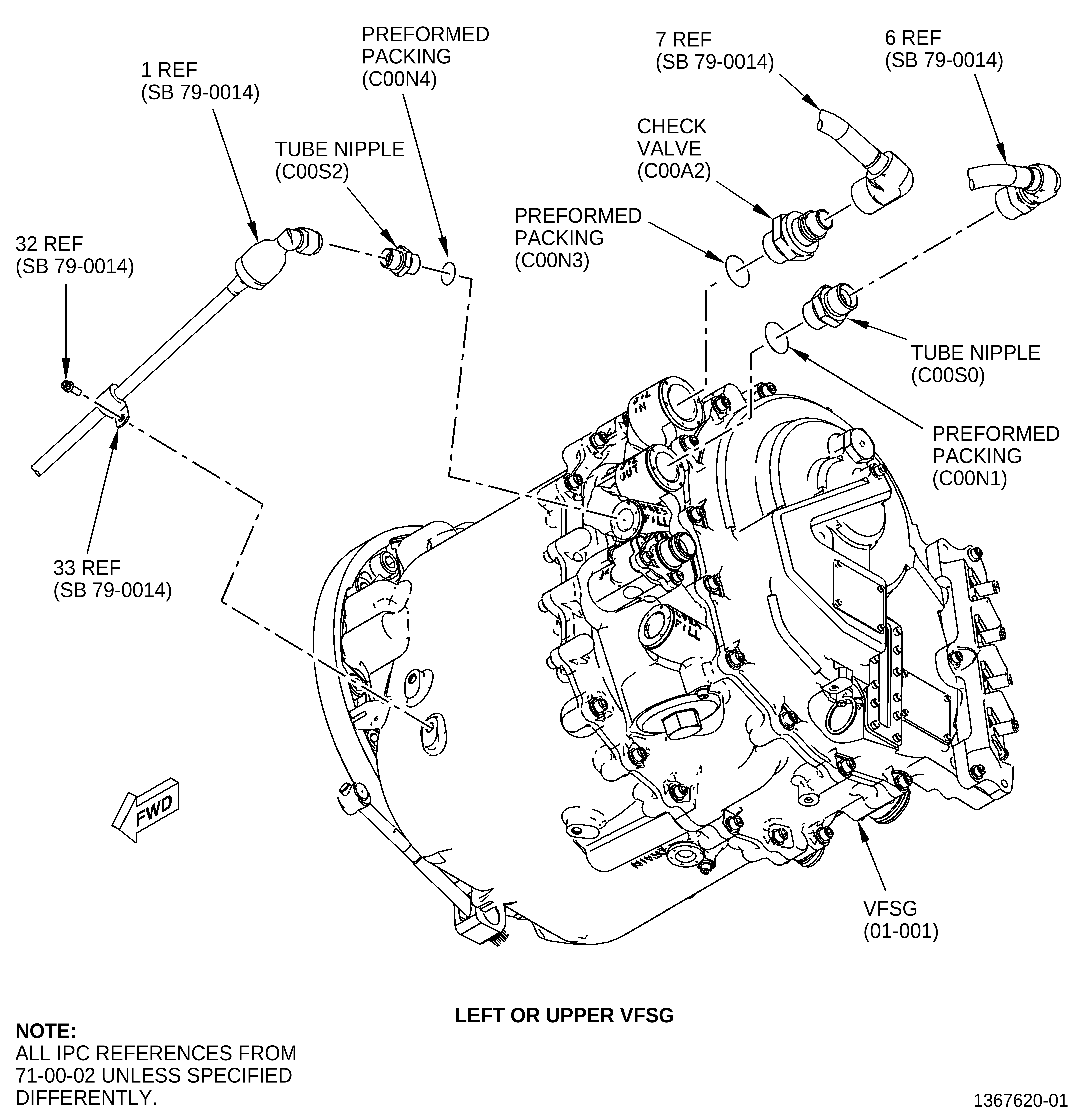
| (7) | Install the oil tubes/hoses on the lower VSFG as follows: |
| (a) | Connect the VFSG oil tube hose (9, Figure 6) to the check valve (C00A2). Use a backup wrench and crowfoot 90 degrees to torque the B-nut to 938-1102 lb in. (106.0-124.5 N.m). |
| (b) | Connect the VFSG cooling oil tube hose (8) to the tube nipple (C00S0). Use a backup wrench and crowfoot at 90 degrees to torque the B-nut to 662-778 lb in. (74.8-87.9 N.m). |
| (8) | Install the oil tubes/hoses on the upper VSFG as follows: |
| (a) | Connect the oil tube hose (7) to the check valve (C00A2). Use a backup wrench and crowfoot at 90 degrees to torque the B-nut to 938-1102 lb in. (106.0-124.5 N.m). |
| (b) | Connect the VFSG cooling oil tube hose (6) to the tube nipple (C00S0). Use a backup wrench and crowfoot At 90 degrees to torque the B-nut to 662-778 lb in. (74.8-87.9 N.m). |
| (c) | Connect the LH VFSG fill oil tube (1) to the tube nipple (C00S2) at the PRES-FILL port. |
| (d) | Put the LH VFSG fill tube (2) in the clamp block (99080). |
| (e) | Connect the LH VFSG fill oil tube (1, Figure 5) to the LH VFSG fill tube (2). |
| (f) | Attach the LH VFSG fill oil tube (1) to the VFSG (01-001, 71-00-02) with a clamp (5) and a bolt (32). Torque the bolt to 60-70 lb in. (6.8-7.9 N.m). |
| (g) | Use a backup wrench and crowfoot at 90 degrees to torque the B-nut on the LH VFSG fill oil tube (1) at the PRE-SFILL port to 262-308 lb in. (29.6-34.8 N.m). |
| (h) | Use a backup wrench and crowfoot at 90 degrees to torque the B-nut on LH VFSG fill oil tube (1) at the LH VFSG fill tube (2) to 262-308 lb in. (29.6-34.8 N.m). |
| (i) | Continue assembly. Refer to the GEnx-1B EM, 72-00-02, ASSEMBLY 006, Subtask 72-00-02-430-755 from step (11)(j) thru (11)(o). |
| (9) | Install a cushion loop clamp (33) on the right oil fill tube. |
| (10) | Install the LH VFSG fill tube (2, Figure 5) to the AGB (01-010, 72-00-05) as follows: |
| (a) | Attach the LH VFSG fill tube (2) to the support bracket on the upper drain manifold (01-380, 72-00-05) with a cushion loop clamp (5) and one bolt (35-210, 79-22-10). |
| (b) | Attach the LH VFSG fill tube (2) to the bracket (01-270, 72-00-05) with a cushion loop clamp (5) and a bolt (35-015, 79-22-10). |
| (c) | Torque the bolts (35-210, 79-22-10) and (35-015, 79-22-10) to 32-38 lb in. (3.6-4.3 N.m). |