| COMMERCIAL ENGINE STANDARD PRACTICES MANUAL | Dated: 03/20/2023 | |
| SPM 70-00-03 MACHINING DATA | ||
| COMMERCIAL ENGINE STANDARD PRACTICES MANUAL | Dated: 03/20/2023 | |
| SPM 70-00-03 MACHINING DATA | ||
| TASK 70-00-03-800-004 |
| 1 . | Machinability. |
| WARNING: |
|
| A. | Machinability is a relative term used to describe the amount of effort required to cut or remove material. Two major factors which affect the machinability of any material are its hardness and strength. Other factors are heat dissipation, work hardening, abrasiveness, and tool wear. Machinability directly affects the cost of production of machined parts. |
| B. | The degree of machinability of materials can only be accurately determined by testing. Using the same cutting conditions (depth of cut, feed, lubrication, etc.) and cutting tools with the same characteristics, cutting speeds are experimentally determined using a lathe. |
| C. | The principal metals currently used in the manufacture of jet engines are nickel, cobalt, titanium, iron, and aluminum base alloys. Presently vacuum-cast nickel base alloys are the most difficult to machine surpassing even wrought and cast cobalt base alloys. Machining technology has not been able to keep up with the decreasing machinability of new materials. As a result, studies are under way to find new cutting tool materials and methods. Nonconventional machining methods are also being explored. |
| D. | Based on studies of industry practices and machinability, machining recommendations were correlated to provide the nominal initial approach for each machining operation and material. Making any machining operation as effective and functional as possible requires more than average data recommendations on speeds and feeds. Variations from average machining data values must depend upon the total relationship among the machine tool equipment, the fixturing, the part configuration, the part tolerances, the surface integrity requirements, the cutting tool material and design, and the rigidity of setup. |
| CAUTION: |
|
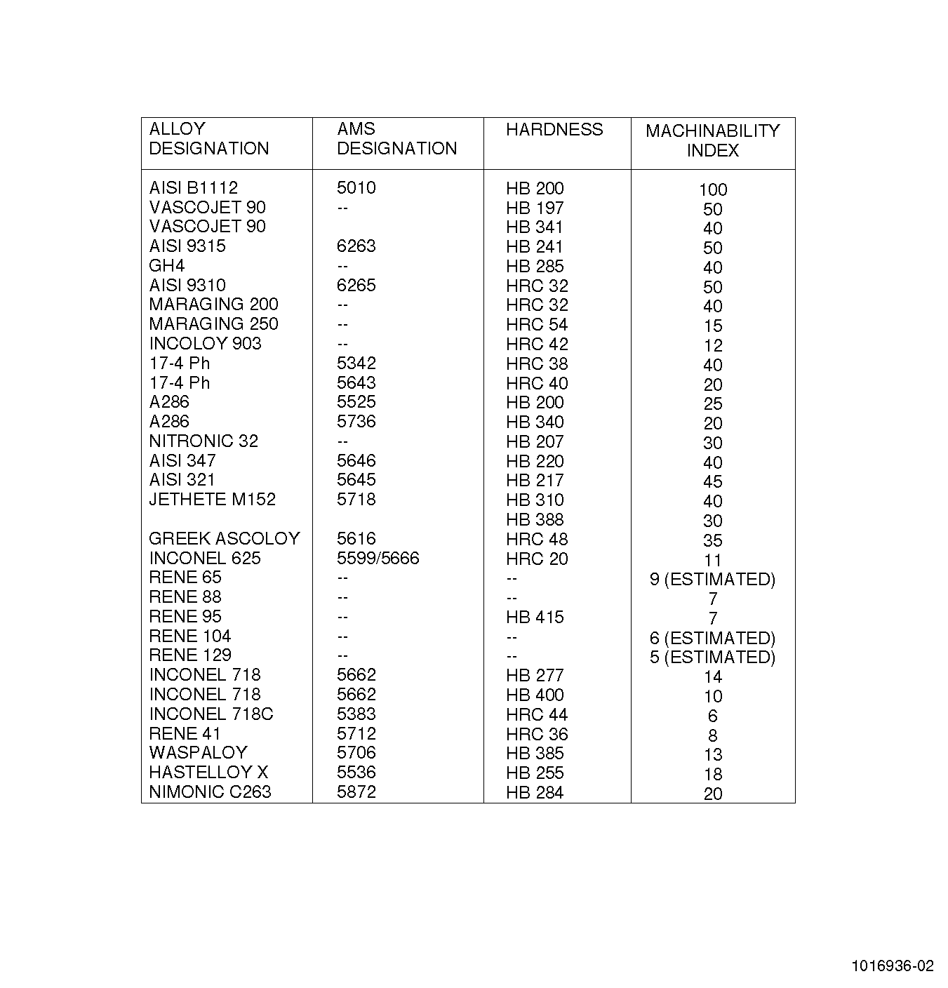
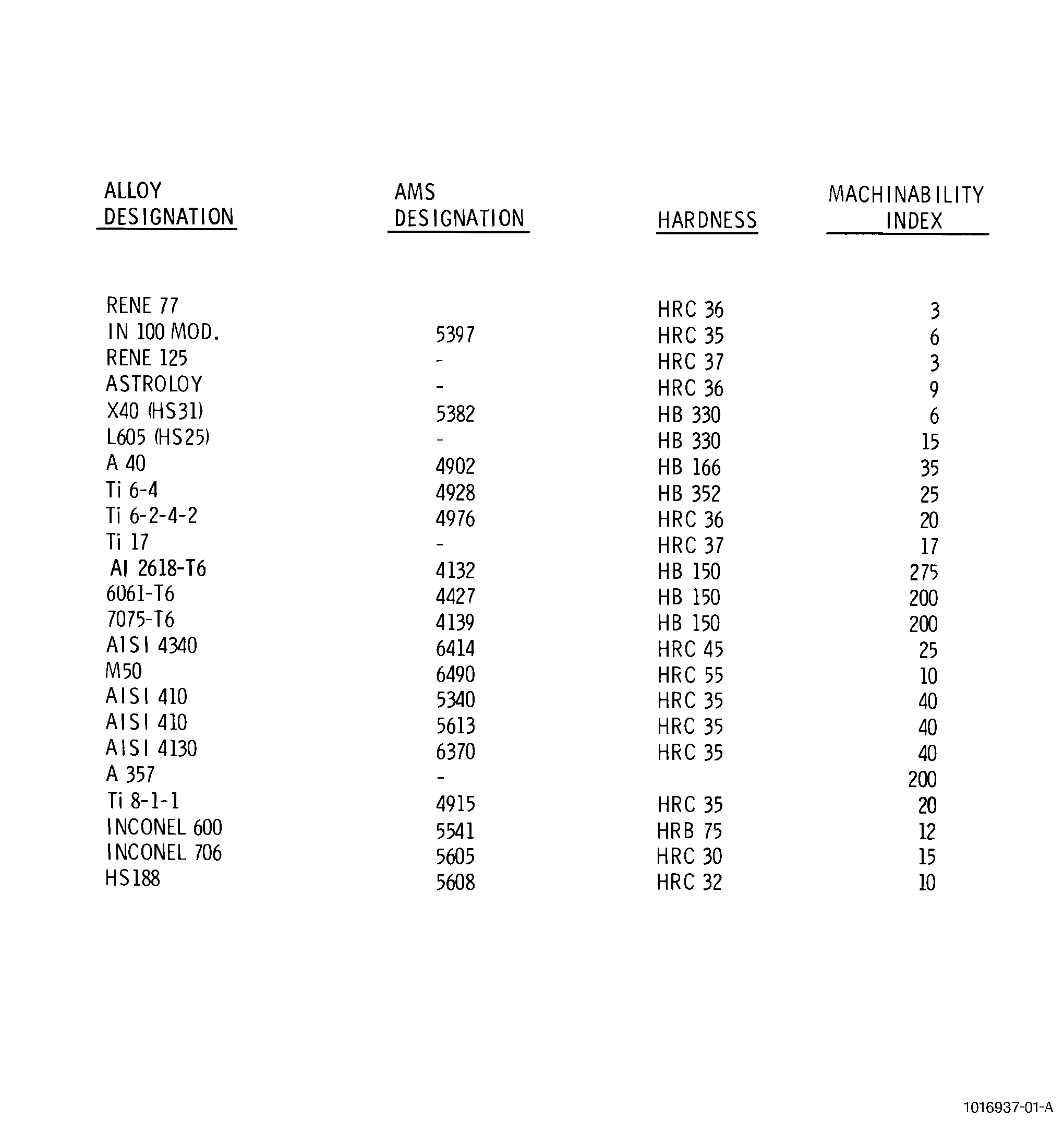
| E. | The machinability index (see Figure 1) shows the degree of machinability of each material as a ratio of the cutting speed used for the material compared to the speed used for the reference material [AISI B1112 (Index 100)], expressed in percentage, to obtain the same cutting tool life. |
| 2 . | Machining Characteristics of Different Materials. |
| Subtask 70-00-03-800-041 |
| A. | Cast materials are more difficult to machine than those which are wrought. Consequently, the degree of machinability may vary for the same material depending on the way it is formed. |
| B. | Stainless steels are the primary steels used in jet engines. It is important to distinguish between austenitic and martensitic stainless steels to determine the proper machining conditions. |
| (1) | Stainless austenitic steels have a tendency to work-harden causing the formation of hard layers in front of the cutting tool. These steels have poor thermal conductivity resulting in concentrated high temperatures at the tip of the cutting tool which is detrimental to tool life. Stainless austenitic steels also are known for their high coefficient of friction which results in a strong tendency to stick and seize causing a more rapid destruction of cutting tools. |
| (2) | Stainless martensitic steels have a structure which is characterized by abrasive carbides (chromium carbide). The carbides are responsible for greater wear of the cutting tools. |
| C. | Nickel-base alloys are characterized by a high elastic limit, a resistance to shear, and a tendency to work harden and seize under certain conditions. The conditions for machining nickel-base alloys are the same as those used for machining stainless austenitic steels. |
| (1) | Powerful machines and solid cutting tools, capable of supporting the forces and dissipating heat rapidly, are required to machine nickel-base alloys. |
| (2) | Machining of nickel-base alloys develops high pressures between the work and the cutting tool that create a layer of deformed metal on the surface of the work. The deformation leads to a hardening that makes further machining more difficult. When this occurs, a stress-relieve heat treatment may be recommended following the machining operation. |
| (3) | Well sharpened tools which produce a positive cut rather than push metal, combined with sufficiently high feeds and cut depths are required to reduce work hardening of the metal. |
| D. | Cobalt-base alloys are similar to nickel-base alloys in machining characteristics. They have properties of high elasticity and a tendency to work-harden and stick. |
| (1) | Cobalt-base alloys require the use of high power equipment which is free of vibrations. |
| (2) | Cutting tools must be solid and rigidly held reducing deflection of the tool through reduction of the cantilever and the use of strong tool holding systems. |
| E. | Titanium-base alloys are more difficult to work than steels. However, these alloys can be machined with no difficulty in shops equipped to machine stainless steels. |
| (1) | Titanium-base alloys require the use of abundant cooling fluid and a limitation of machine speed to reduce high tool temperatures caused by poor thermal conductivity. |
| (2) | The low modulus of elasticity of titanium-base alloys (close to one-half that of steels) gives rise to vibrations and chattering if the work is insufficiently held, if the cutting tools are not rigidly held, and/or if the machines are not powerful enough. |
| (3) | During heat treatments in air, a superficial layer of very hard oxides or nitrides can form on some alloys. The removal of this very hard layer by machining, is a delicate operation. It is preferable to sand blast or chemically strip prior to machining. |
| F. | Aluminum-base alloys are generally easily machined with cutting tools. Machining characteristics particular to aluminum are as follows: |
| (1) | Aluminum-base alloys have a low modulus of elasticity (close to one-third that of steel). Care must be taken in securing the work to prevent deflection. If necessary, supporting devices (steady rests) and reduced cutting forces can be employed, in accordance with the geometry. |
| (2) | Some aluminum alloys have a noticeable abrasive effect on the cutting tool; this is a function of the hardness of the part, its structure, and most of all, its silicon content. |
| 3 . | Turning. |
| Subtask 70-00-03-800-042 |
| WARNING: |
|
| A. | General. |
| Turning is the machining operation whereby an external cylindrical or conical surface is generated through the direct action of a rotating workpiece and the longitudinal travel of a single point cutting tool. When this same action is applied to generate an internal surface, the operation is called boring. Facing is a special type of turning where the cutting tool moves perpendicular to the axis of rotation of the workpiece, generating a flat surface. |
| B. | Equipment. |
| Equipment for turning must have the capability to hold and rotate the workpiece while holding the tool stationary except for linear movement. Most turning is done on lathes. There are several types of lathes but the most common is the engine lathe, a heavy duty machine tool that utilizes typical lathe components: lathe bed, headstock assembly, tailstock assembly, carriage assembly (includes tool holding block or post), speed and feed change gearboxes, lead screw, feed rod, and cooling system. |
| C. | Materials. |
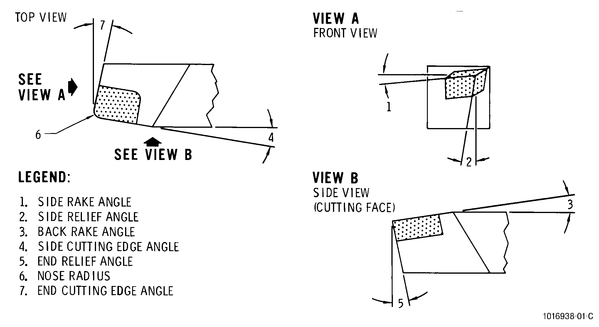
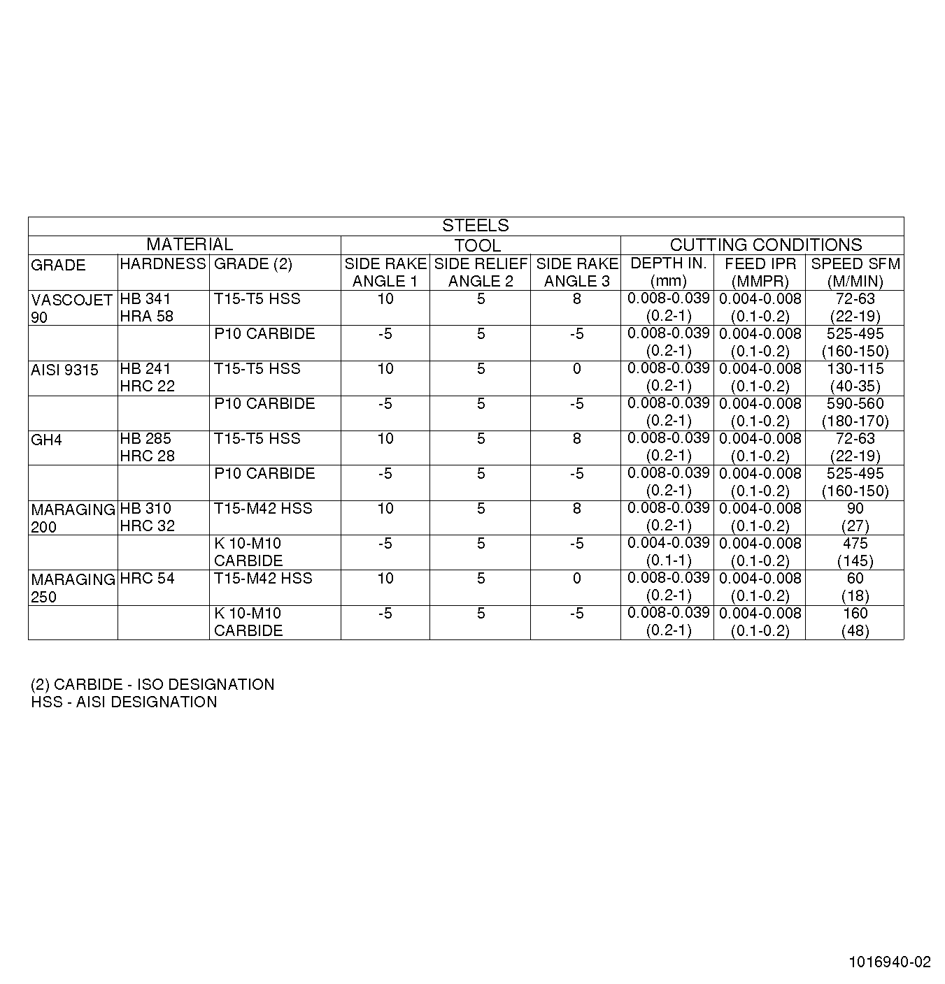
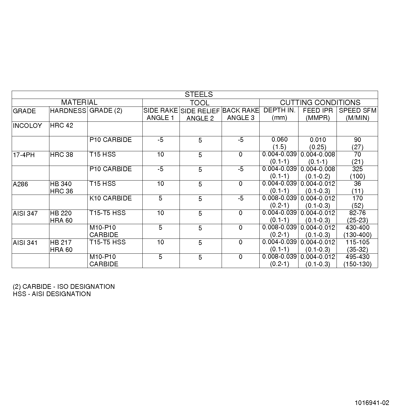
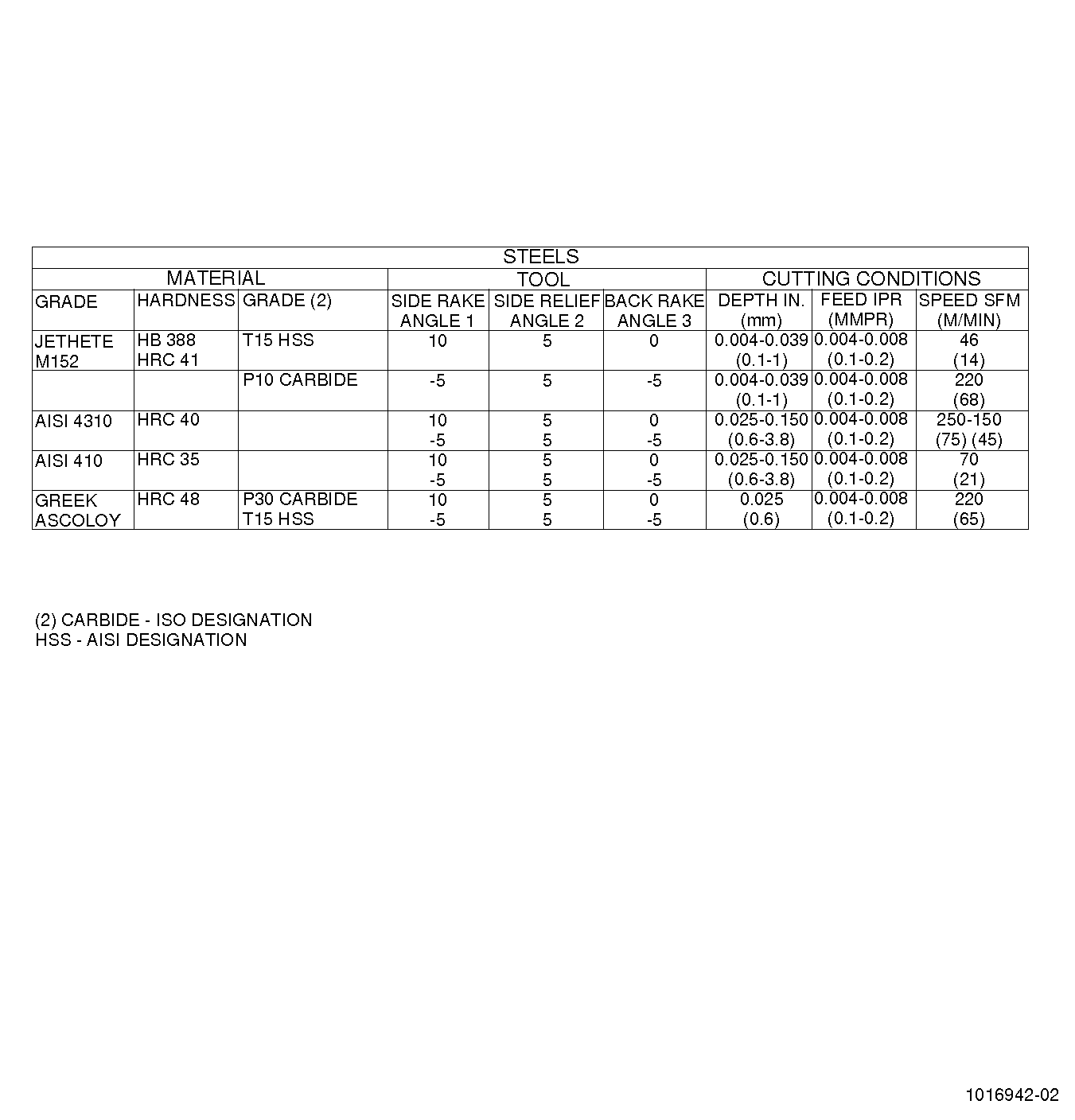
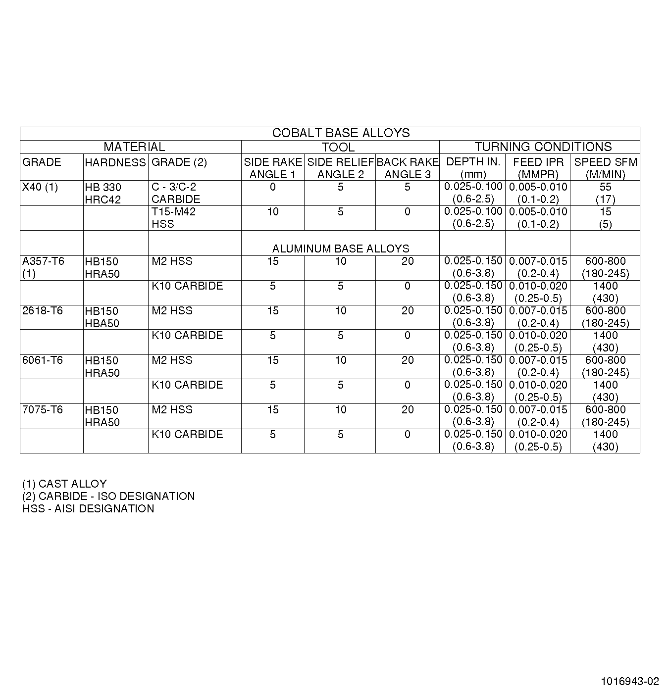
| (1) | Cutting tools. See Figure 2. |
| (a) | Two types of materials are used for cutting tools: high speed steels, designated by AISI specifications; and metal carbides designated by ISP specifications. |
| (b) | The use of high speed steels is limited by its hot hardness. The cobalt grade of HSS can be used for turning of work materials which have a hardness below HRC52. Metal carbides are used as the tool for turning most materials, but are required with materials having hardness of HRC52 or harder. Care must be exercised in the use of carbides since they have poor impact resistance. |
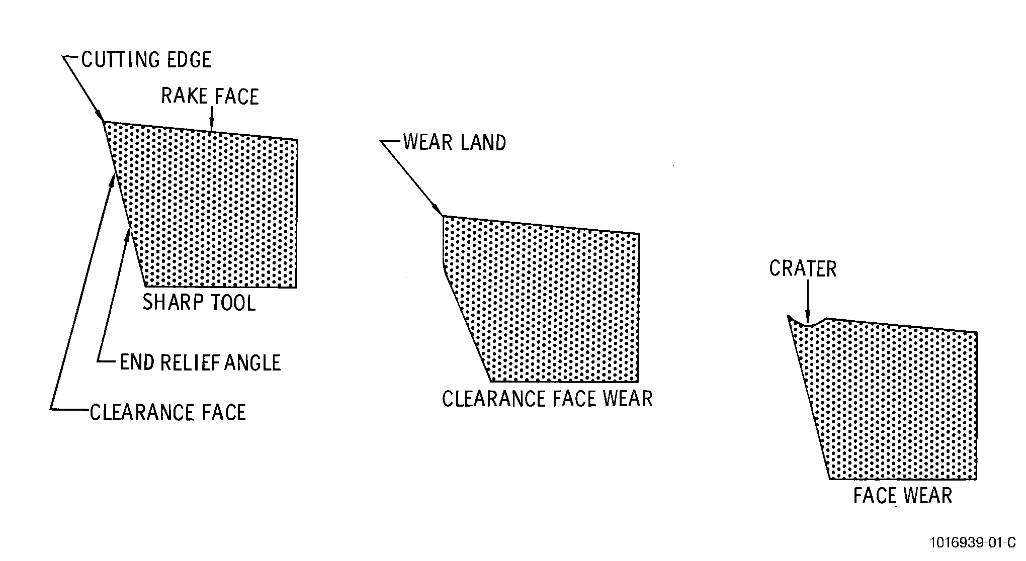
| (c) | The ability to maintain sharp cutting edges on tools reduces work-hardening, excessive cutting forces and potential distortion of the workpiece. A cutting tool is subject to wear on the side clearance face and side rake face. For given machining conditions, wear increases with time and reaches a level which requires replacement or grinding of the tool. The level of acceptable evenly distributed wear is 0.015 inch (0.4 mm) and of localized wear is 0.020 inch (0.5 mm) maximum. See Figure 3. |
| (d) | The tool materials and procedures for turning plasma spray coatings are basically the same as for turning solid materials, however, more critical limits are placed on the range of cutting speeds, depths cut, feed rates and the geometry of the cutting tool. |
| (2) | Cutting fluids. |
| (a) | Cutting fluids are used for cooling and lubricating the cutting tool and workpiece. There are 4 classes of cutting fluids: straight cutting oils, water soluble oils, semi-synthetic fluids, and synthetic fluids. |
| (b) | The addition of a 10 percent chlorine containing extreme pressure additive produces cutting fluids of a higher lubricating value. |
| NOTE: |
|
| (c) | Cutting fluids, especially those used with the machining of aluminum and copper alloys, must be inactive, i.e., must not cause any chemical reaction with the workpiece. |
| D. | Procedure. |
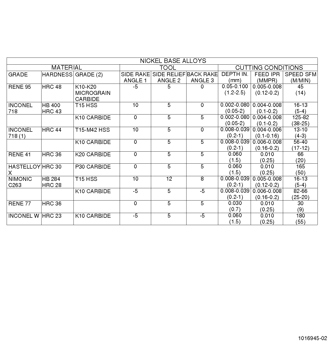
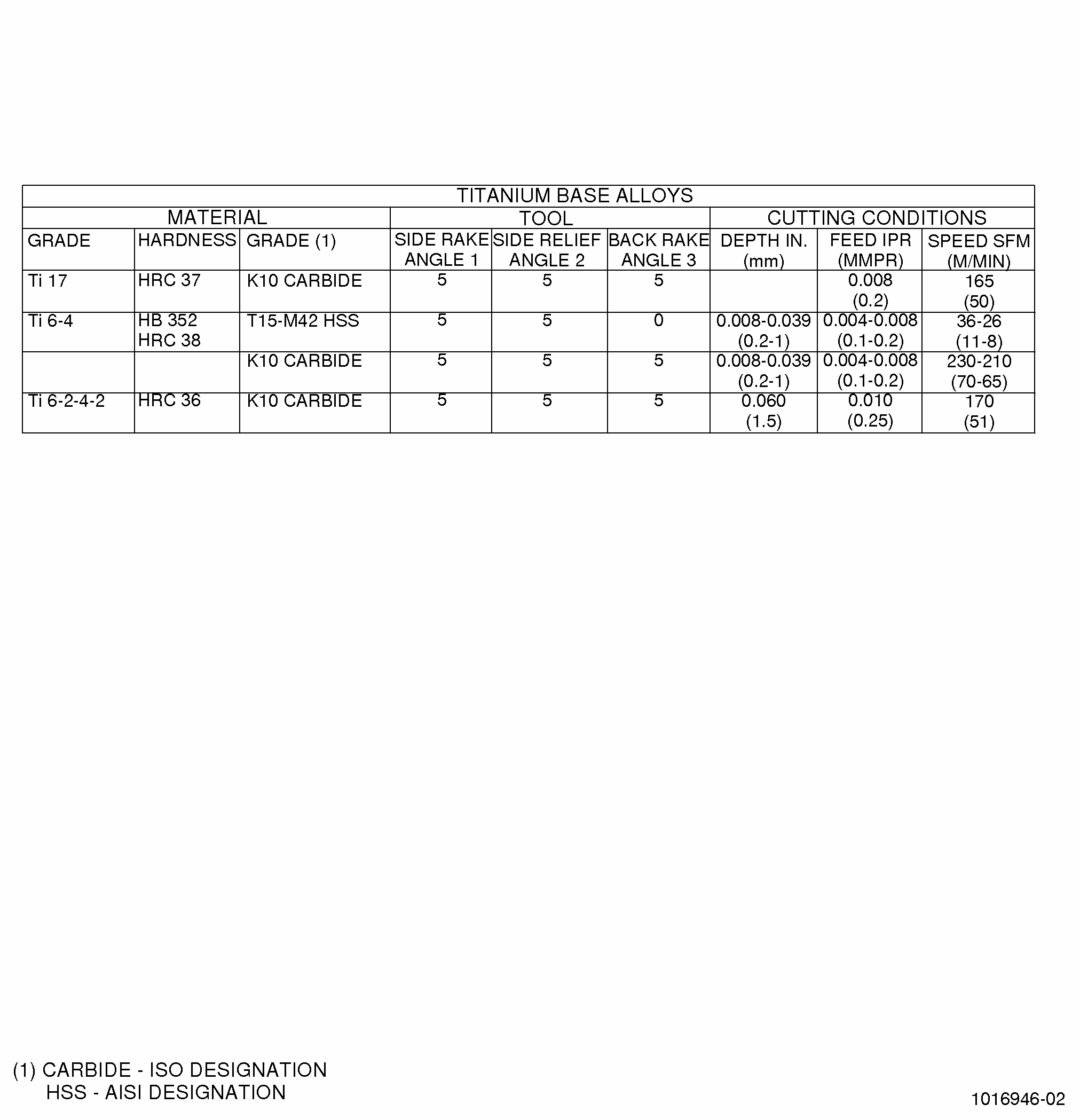
| Cutting tool life expectancy for parameters recommended in Figure 4 is 60-90 minutes for high speed steel tools and 30-45 minutes for carbide tools, rated in continuous cut with soluble oil cutting fluid. Tool life will change if the machining parameters or cutting fluid is changed. Tool life is most critically effected by the surface rotational speed of the workpiece. Materials which are difficult to machine have more critical ranges of cutting speeds. |
| E. | Quality Assurance. |
| Check machined parts to be sure that edges are free of burrs and rolled metal. |
| 4 . | Milling. |
| Subtask 70-00-03-800-043 |
| WARNING: |
|
| A. | General. |
| Milling is the machining operation whereby a surface is generated by incremental removal of metal from the work-piece by the rotation of a single tooth (fly) or multi-tooth (milling) cutter. Generally the workpiece is fed to the milling cutter but in special cases the cutter is moved past a stationary workpiece. |
| B. | Types. |
| There are 2 basic types of milling: peripheral and face. The types of milling are described as follows: |
| (1) | Peripheral milling generates a surface parallel to the cutter axis, by teeth on the periphery of the cutter. A further distinction in peripheral milling is that it can be either up milling (conventional) or down milling (climb). Up and down milling are defined as follows: |
| (a) | Up milling. |
| The cutter rotates against the direction of feed of the workpiece. This type of milling has a minimal initial chip which increases as the tooth progresses into the cut. |
| (b) | Down milling. |
| The cutter rotates in the same direction as the feed of the workpiece. Down milling has a maximum initial chip which decreases to almost zero thickness at the end. Down milling is generally preferred over up milling with proper setup except where depth of cut varies excessively or where very rough surfaces are encountered (castings or forgings). |
| (2) | Face milling generates a surface perpendicular to the milling cutter axis and is the result of the cutting action of teeth that occupy both the face and periphery of the cutter. |
| C. | Equipment. |
| (1) | Milling machines are generally built for versatility (general purpose) or for productivity (manufacturing) or for special applications. Knee and column type mills fall into the general purpose classification. Bed and planer type mills fall into the manufacturing classification. Special milling machines are usually custom designed for specific applications. |
| (2) | Bed type milling machines are rugged and have the capability of making heavy cuts. This type of mill has the table mounted directly on the bed and the table has only longitudinal movement, however, bed type mills may be made more flexible by adding a transverse motion to the table. For given setup, the spindle head is normally clamped in position, however, on other types of operations, vertical movement of the spindle occurs. The spindles can be both horizontal and vertical and a milling machine may have one, 2, 3, or even 4 spindles to permit milling of multiple surfaces in a single pass. |
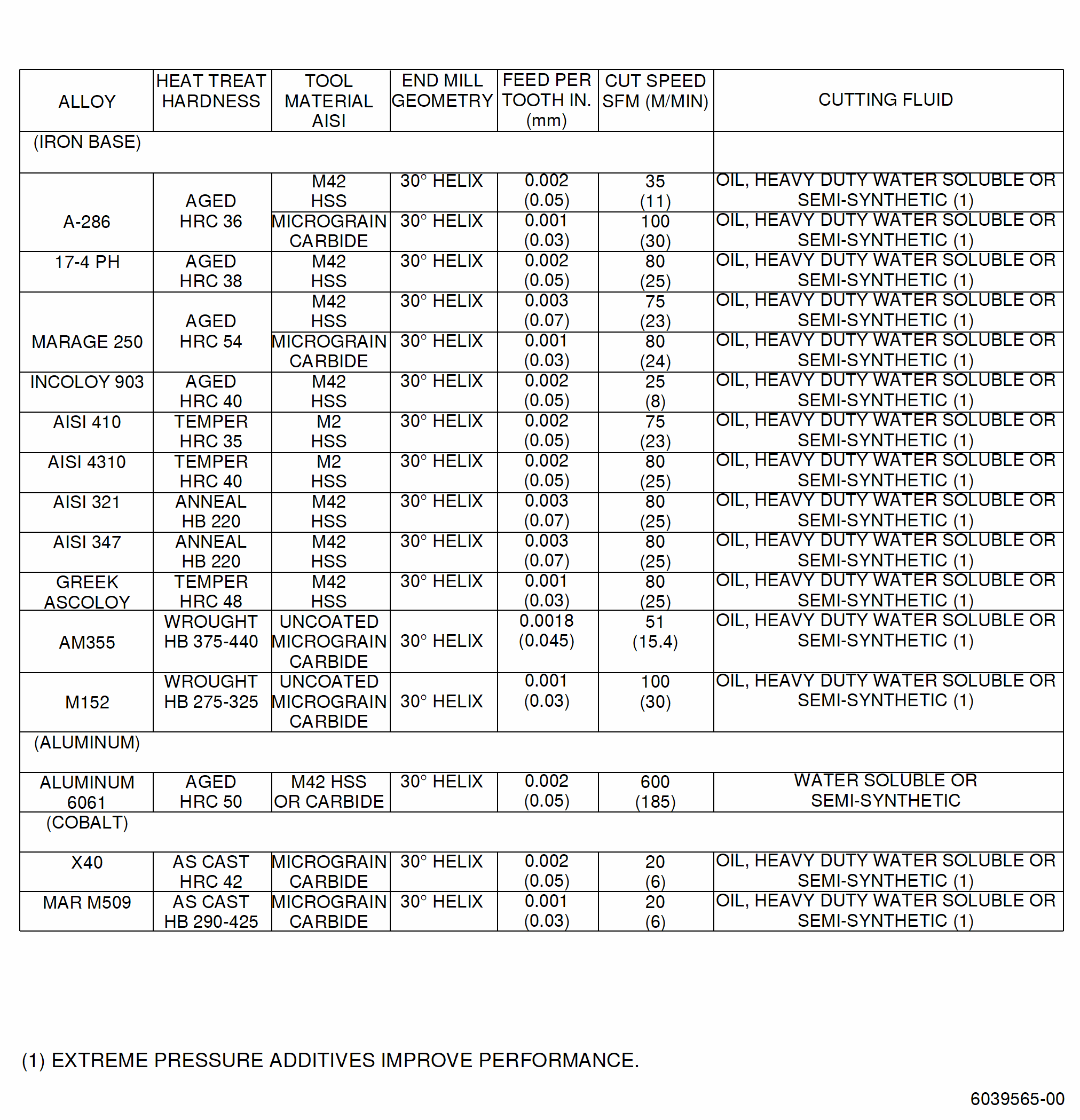
| (3) | The most difficult type of milling is end milling. The end milling condition involves both up milling and down milling on the periphery of the cutter while simultaneously making a face cut. Because end milling combines the challenges of both face milling and periphery milling, end milling data is shown in Figure 5. |
| D. | Materials. |
| (1) | Cutting tools. |
| (a) | It should be noted that while high speed steel (HSS) tooling is indicated in Figure 5, carbide tooling should be considered. If carbide tooling is to be used, attention should be given to the setup geometry of the tool because carbide is more affected by the angle of entry than HSS. |
| (b) | The types of tool wear prevailing in milling are similar to those encountered in turning. In milling, however, tool wear resulting from flaking and cracking is more frequent due to the mechanical and thermal shocks exerted on the cutting edges and discontinuous cutting of the workpiece. The criterion ruling over tool wear is the relief angle wear. The permissible distributed amount of wear is 0.012 inch (0.3 mm) and maximum allowable localized wear is 0.020 inch (0.5 mm). |
| (2) | Cutting fluids. |
| (a) | Cutting fluids are used to cool and/or lubricate the cutting tool and workpiece. These fluids are classified as straight cutting oils, water soluble cutting oils, and semi-synthetic fluids. The type of work to be performed determines which cutting fluid to use. |
| (b) | Cutting fluids, especially those used with the machining of copper and aluminum, must be inactive i.e., must not cause any chemical reaction with the workpiece. |
| E. | Procedure. |
| (1) | Milling parameters. |
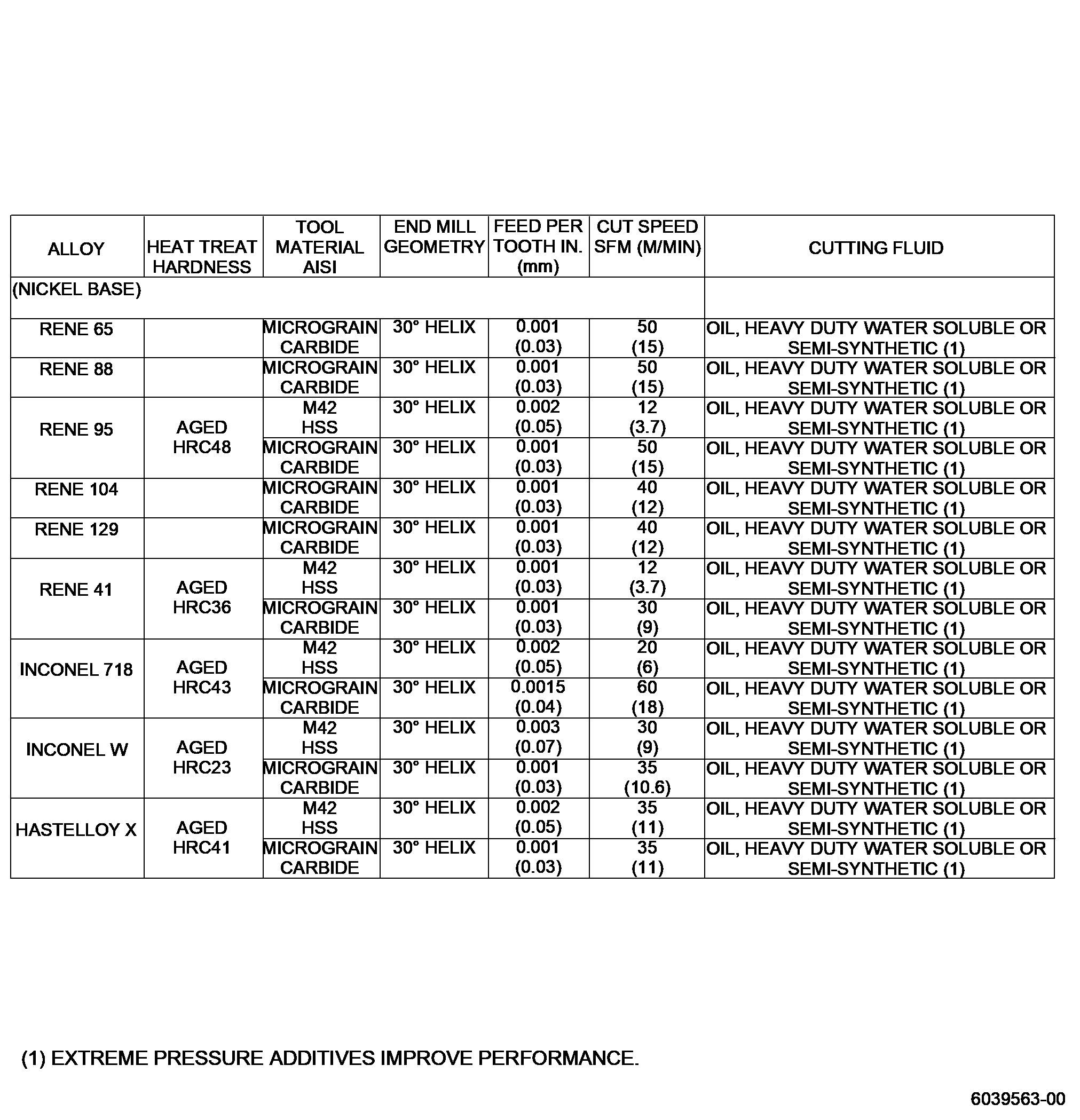
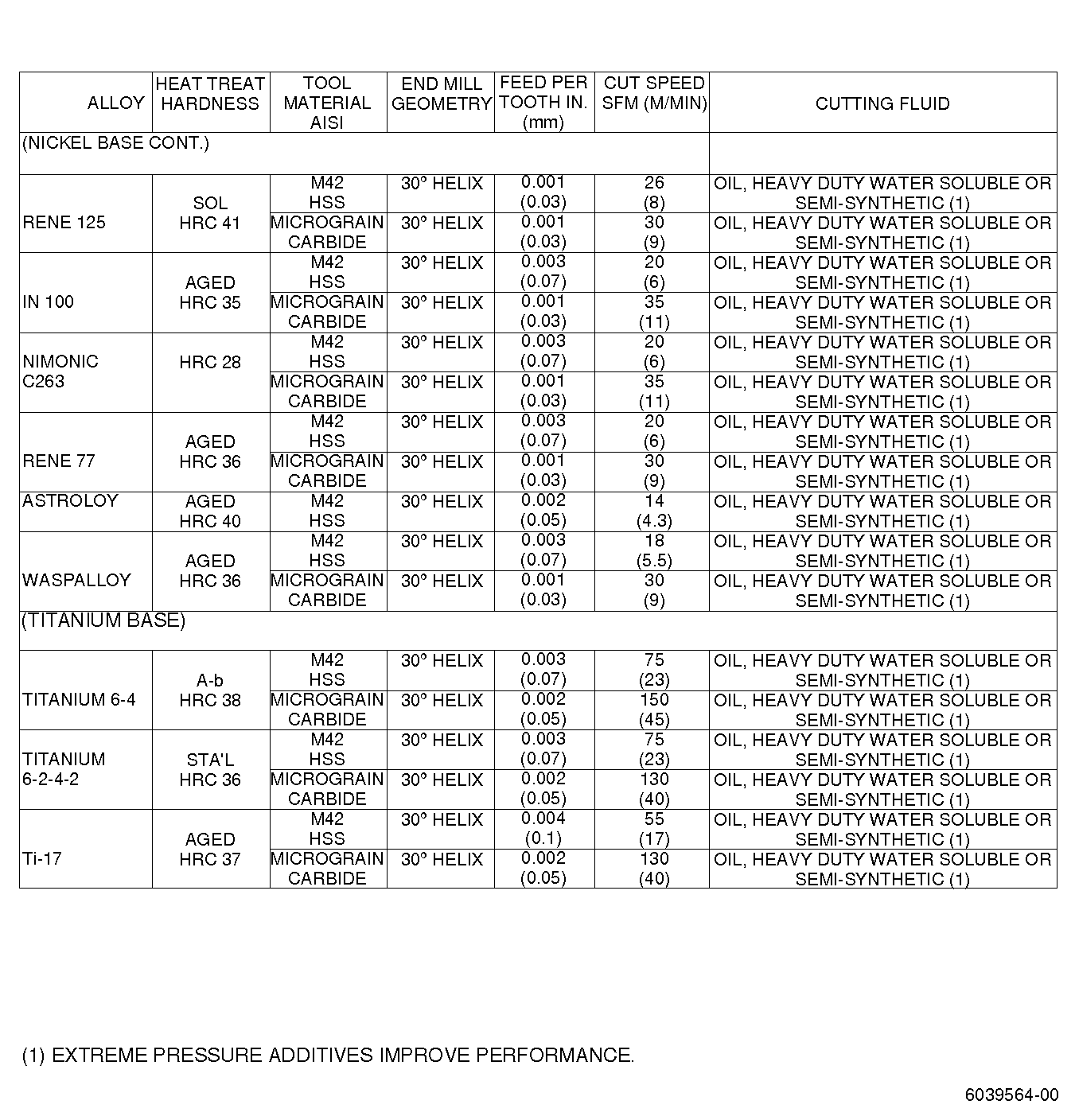
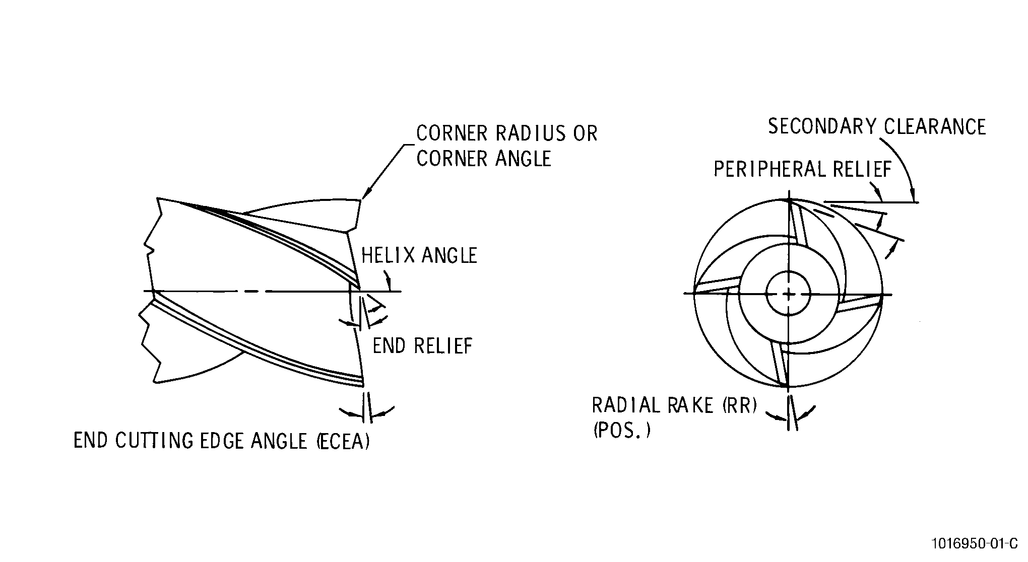
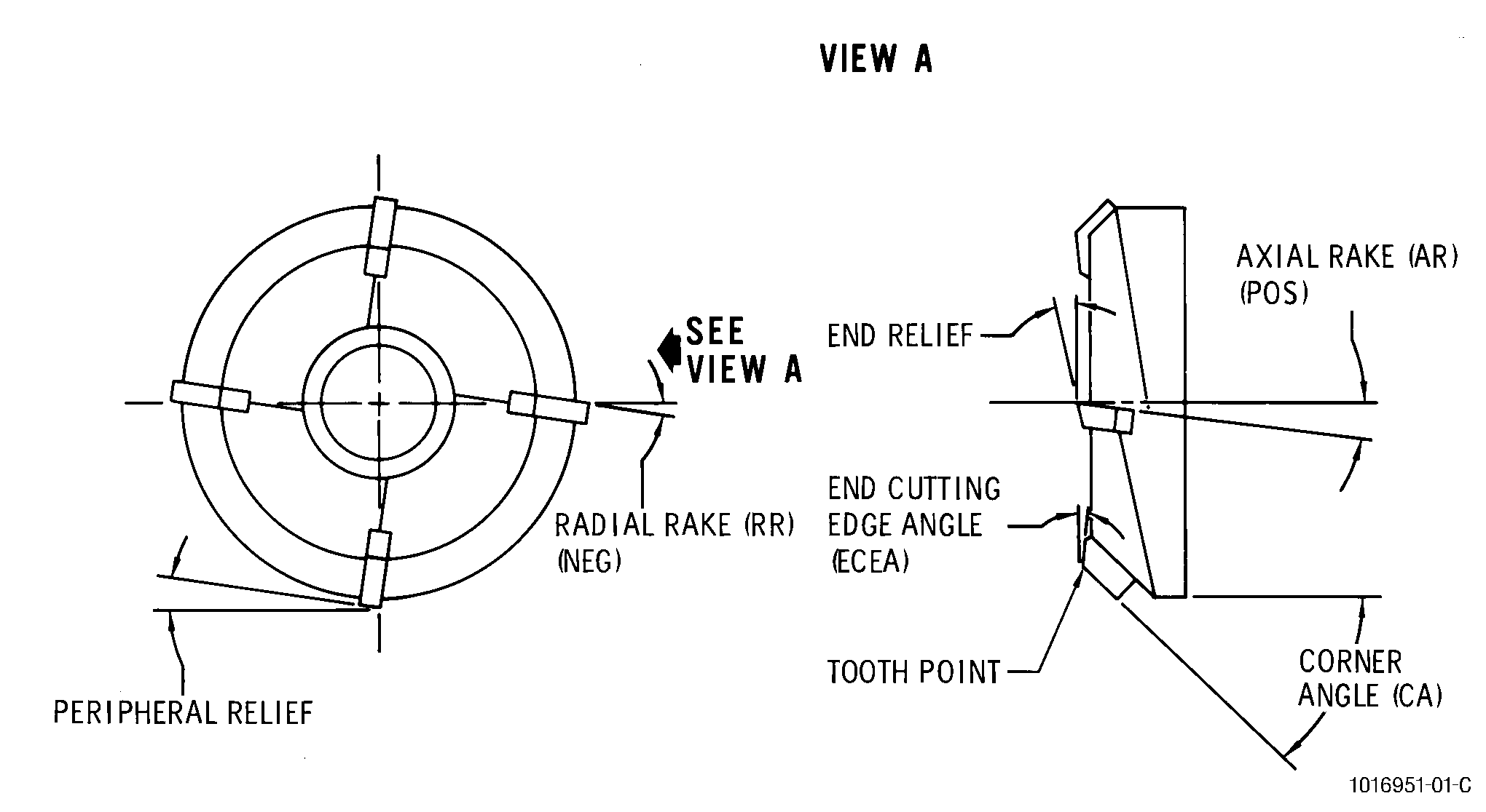
| The parameters required to mill specific materials are listed in Figure 5. The conditions shown are for rough milling using end mill tooling of high speed steel with expected tool life of 60-120 minutes using coolant. For finish milling operations, these values should be adjusted per the dimensional and surface requirements specific to each part. Figure 6 and Figure 7 show the nomenclature of face and end milling cutters. |
| (2) | Application of cutting fluid. |
| (a) | Milling operations require the use of 2 nozzles directing a copious supply of fluid to both the incoming and outgoing sides of the cutter. The fluid from one nozzle is pumped through the cutting zone by the cutter teeth while fluid from the other nozzle washes away the chips as they emerge from the cutter. Standard round nozzles are sufficient for narrow cutters. Wide cutters require using fan-shaped nozzles at least three-quarters the width of the milling cutter to provide good coverage. |
| (b) | For face milling, use of a ring-type distributor consisting of a tube with many small holes can be beneficial. This directs the fluid at all cutting edges and keeps the cutter completely bathed in fluid to provide even cooling. When a particular size face mill is used often, the type distributor can be supplemented with a special fan nozzle with a curved opening to match the cutter radius. |
| F. | Quality Assurance. |
| Check milled part to be sure that machined edges are free of burrs and rolled metal. |
| 5 . | Grinding. |
| Subtask 70-00-03-800-044 |
| WARNING: |
|
| A. | General. |
| Grinding is the machining operation whereby a fine surface finish is generated by the cutting action of a very large number of small irregularly shaped abrasive particles bonded into a cutting wheel (belt grinding is not covered here). Small multipoint cutting edges cut simultaneously to produce very fine surfaces and close dimensional control while providing the capability to machine extremely hard materials. |
| (1) | Grinding practices used for jet engine alloys is unlike the grinding practices used for most other metals. The requirements and specifications controlling the permissible grinding conditions are very similar to those used for the preparation of laboratory fatigue and tensile specimens. Such necessary stringency results from the fact the conventional grinding practices can induce residual stresses that significantly lower the fatigue strength of highly stressed parts such as compressor and turbine blades. |
| (2) | It is difficult to recommend a set of conditions that will accurately meet all grinding situations, however, the following general grinding information will help establish the background for application of the practices used in the grinding of jet engine materials. |
| (a) | Grit sizes. |
| A grit as course as the finish and form holding requirements of the job permit should be used. |
| (b) | Grade selection. |
| 1 | As the area of contact increases, the wheel hardness grade should decrease. |
| 2 | Cylindrical grinding. |
| One grade harder wheel than that required for surface grinding should be used. |
| 3 | Internal grinding. |
| One grade softer wheel than that required for surface grinding should be used. |
| (c) | G-ratio. |
| G-ratio is the relationship of metal removed to the volume of wheel worn away. A low G-ratio means difficult to grind material under one given set of conditions. |
| (d) | Stress conditions. |
| Where the grinding G-ratio is more important than a low stress surface, the friability of the grit may be reduced and the wheel speeds increased. |
| (e) | Grit sharpness is of great importance to the grinding of high-temperature materials. Other than wheel dressing, a sharp grit is obtained by one of the following means: |
| 1 | A friable grit that will fracture under grinding pressure to expose sharp new edges. |
| 2 | A wheel just soft enough to break down under grinding pressure to expose new grains. |
| (f) | Wheel loading must be avoided to prevent stress buildup. Frequent wheel dressing is essential. |
| B. | Equipment. |
| There are 2 major categories of grinding machines: surface grinding machines and cylindrical grinding machines. These machines may be equipped with either vertical or horizontal spindles. The work table for either grinding machine may be either reciprocating or rotary. |
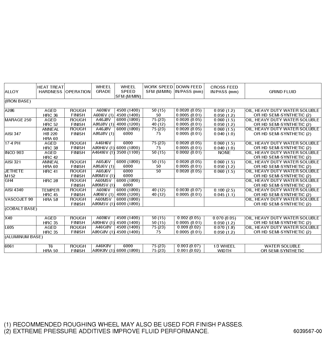
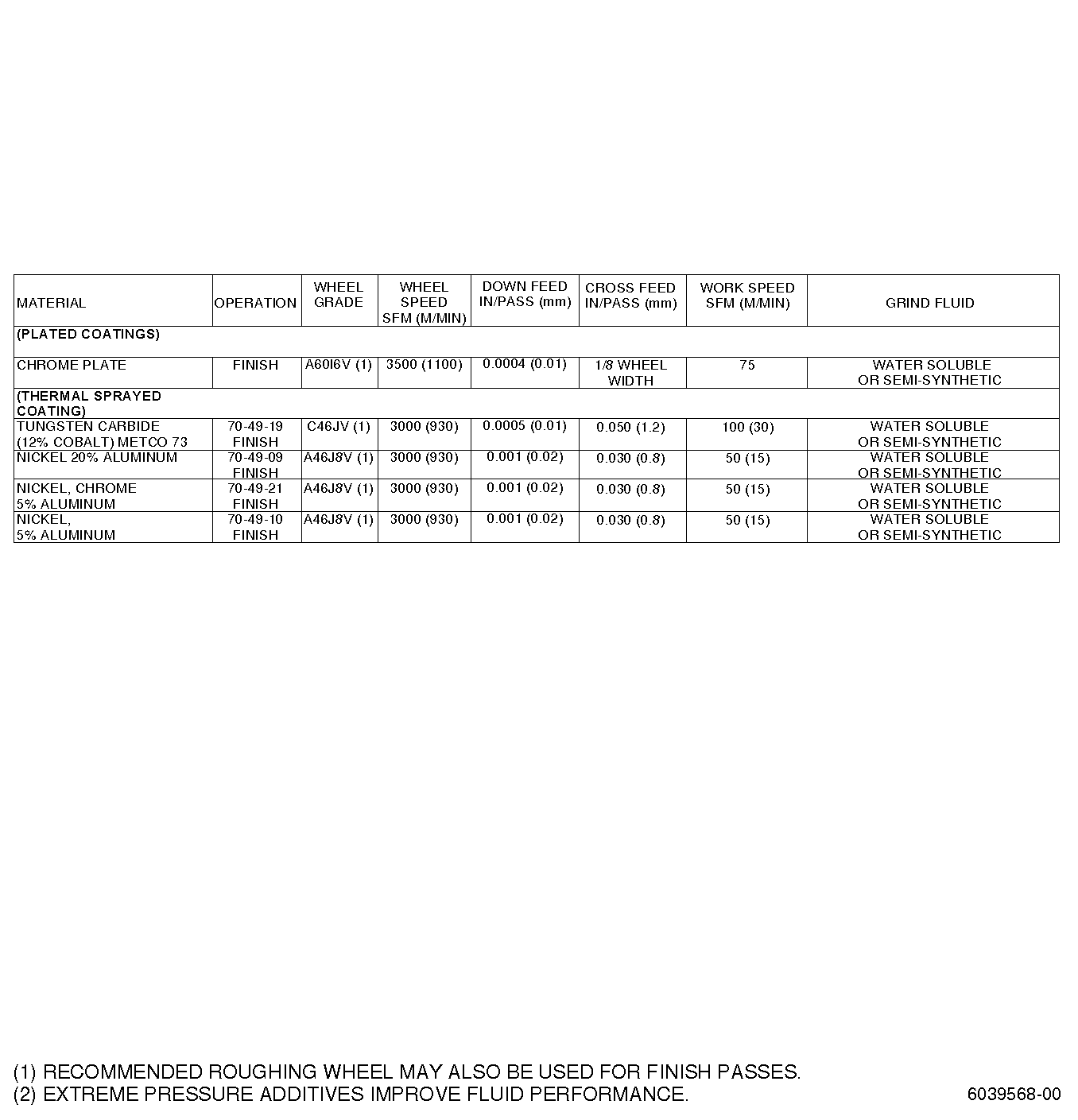
| C. | Materials. |
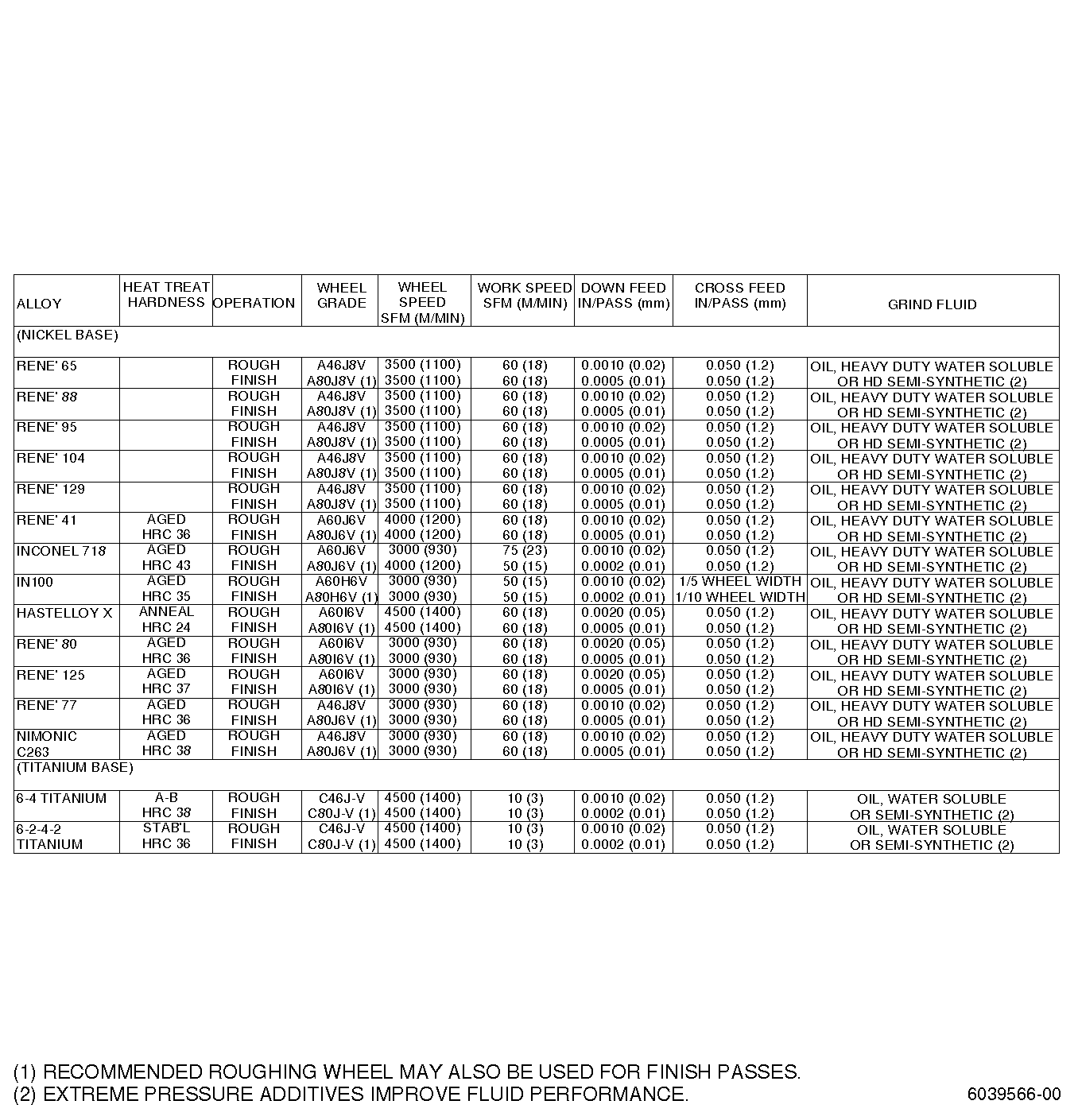
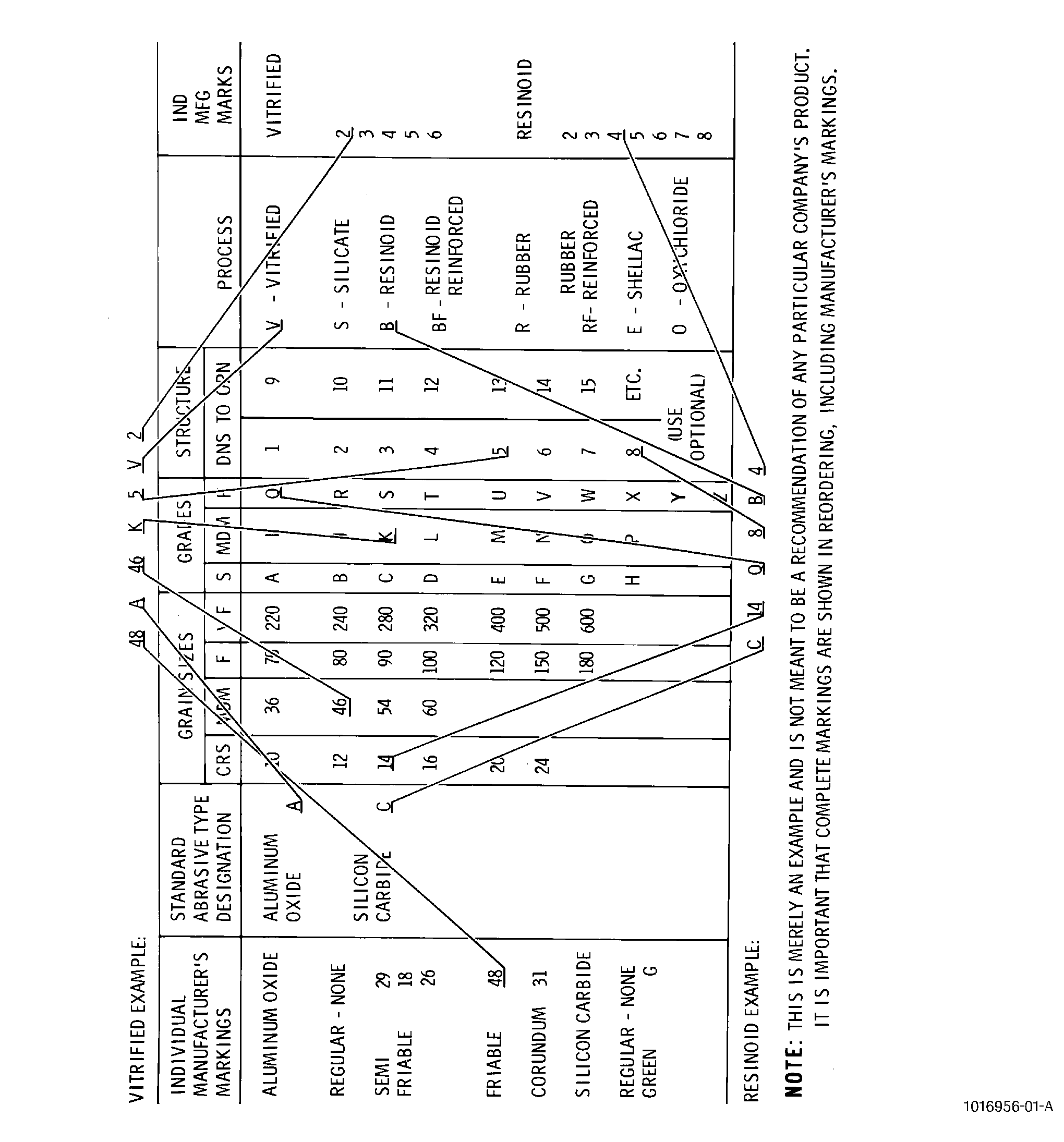
| Figure 8 provides the essential facts to identify grinding wheel grade and speed, work speed, down feed, cross feed, and grinding coolant used to achieve minimum residual stress in parts. Figure 9 shows the interpretation of grinding wheel markings. |
| D. | Procedure. |
| (1) | Grinding. |
| (a) | The parameters for grinding specific alloys are shown in Figure 8. |
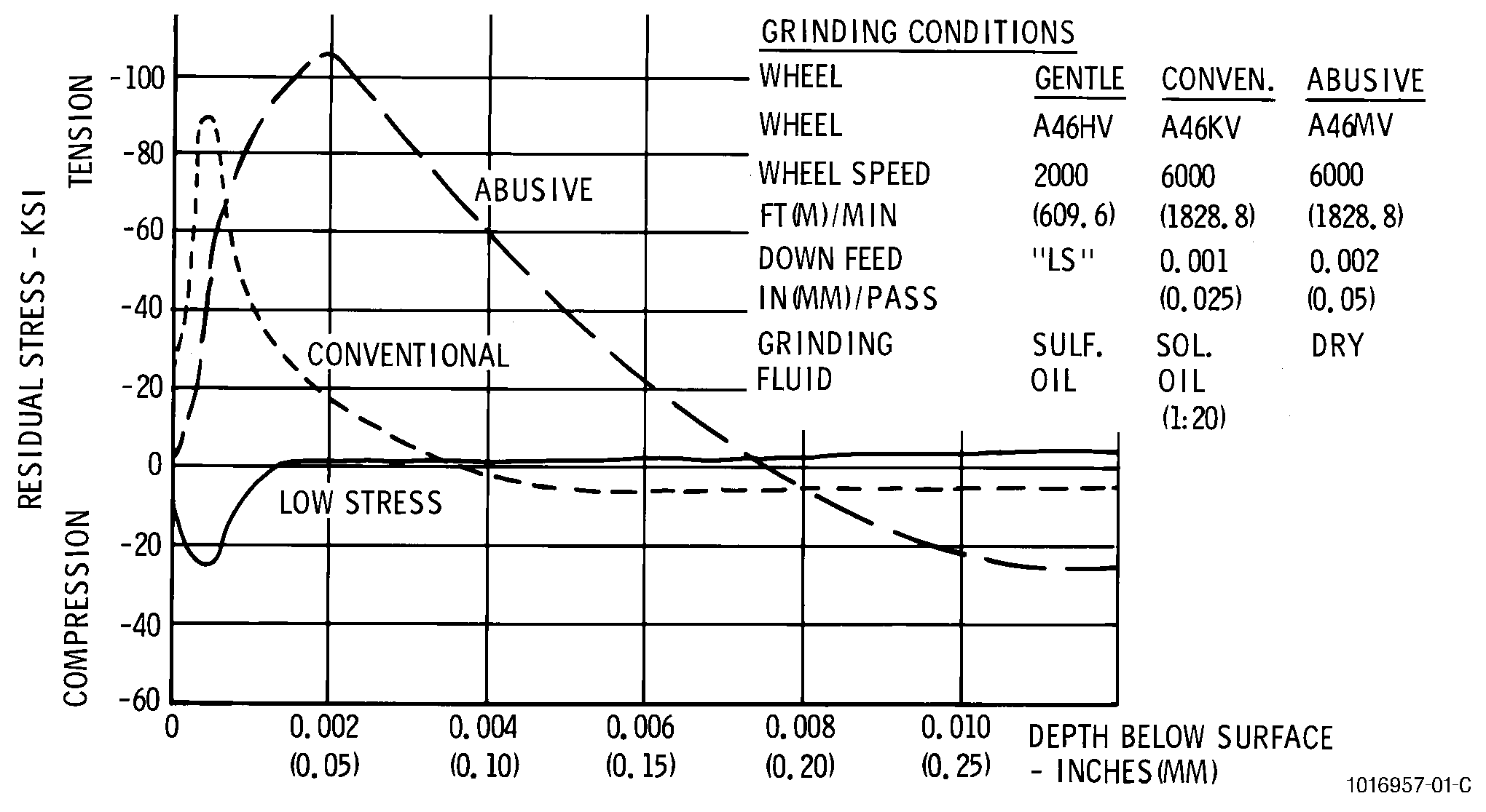
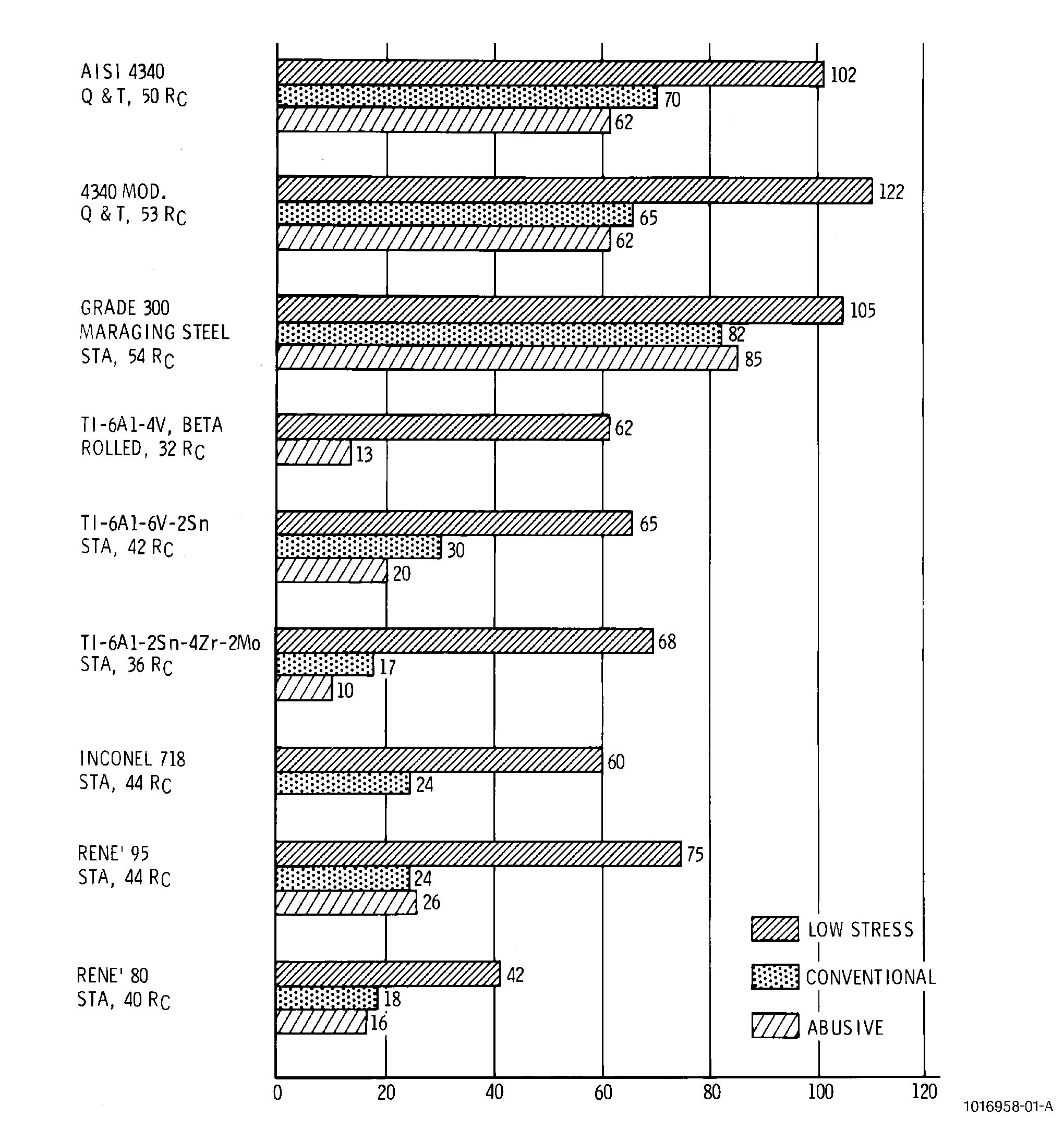
| (b) | Figure 10 shows the effect of low stress, conventional, and abusive grinding conditions. A summary of high cycle fatigue response at room temperature for a number of alloys is shown in Figure 11. All of these materials can be successfully ground and can retain high levels of surface integrity providing the proper procedures are employed and adequate controls are enforced. |
| (c) | The results of a large number of controlled grinding tests indicate that abusive grinding practices for nickel-base alloys result when the following are used: |
| 1 | High grinding wheel speeds (over 4000 sfm). |
| 2 | Slow work speeds (under 15 sfm). |
| 3 | Hard bonded grinding wheels (higher than letter J). |
| 4 | Heavy down feeds [over 0.0005 inch (0.013 mm) per pass]. |
| 5 | Improper grinding fluid (sulfo-chlorinated oil being desirable for nickel, cobalt, and iron-base alloys, and water-base coolant for titanium) or improper applications of the fluid during grinding. |
| 6 | Improper or infrequent dressing of the grinding wheel. |
| NOTE: |
|
| (2) | Cutting fluid application. |
| (a) | A copious flow of cutting fluid at low pressure will generally provide good results for grinding operations. Where application of a large volume of fluid results in undue splashing, it is better to install splash guards on the machine than to reduce the coolant flow. |
| (b) | The normal methods of applying fluids to grinding operations remove little heat until it has dissipated into the mass of the workpiece. Because of the high surface speeds involved, an entrained film of air usually encloses the grinding-wheel surface, and this prevents penetration of the fluid into the cutting zone. Special nozzles can be designed which will force the fluid through the air film and on to the wheel. These nozzles must be placed as close as possible to the workpiece to prevent complete loss of the fluid by the centrifugal force of the wheel. |
| E. | Quality Assurance. |
| Check machined part to be sure that edges are free of burrs or rolled metal. |
| 6 . | Broaching. |
| Subtask 70-00-03-800-045 |
| WARNING: |
|
| A. | General. |
| Broaching is a machining process which generates a desired contour in the machined part by the push or pull cutting action of a tool with multiple, transverse cutting edges that incrementally remove metal. This process is capable of producing close tolerances in simple, plain surfaces and in more complicated forms as well. The broaching form discussed in this standard practice will be dovetail slots only. |
| B. | Cutting Teeth. |
| A dovetail contour can be broached in a workpiece by a single pass of the tool. The tool will normally have 3 basic sections of cutting teeth: |
| (1) | Roughing teeth or slotters which remove approximately 0.003 inch (0.08 mm) of material per tooth (full edge contact). |
| (2) | Intermediate teeth or rough formers which remove approximately 0.003 inch (0.08 mm) per tooth (partial edge contact). |
| (3) | Finish teeth or finish formers which remove from 0.0015 to 0.000 inch (0.038 to 0.000 mm) per tooth (partial to full edge contact). |
| C. | Equipment. |
| Based on the direction of broach travel, there are 2 main types of broaching machines: |
| (1) | The horizontal broach is a general purpose machine suited for either high or low production. It is possible to design for extremely long stroke or obtain the equivalent long stroke by utilizing special vertical locking positions of the work carriage and the appropriate location of the broach ram. Peripheral and accessory equipment can be easily handled with the horizontal broach. The main disadvantages of the horizontal broach are the large floor space requirement and difficult cutting fluid management. |
| (2) | Vertical broaching machines are more adaptable to high production because they are easily automated. Cutting fluid can be easily supplied to the entire broach section but good engineering is necessary to ensure that cutting area is well supplied. Vertical broaches occupy less floor space than the horizontals but require more headroom. |
| (3) | Two basic types of broach cutters are used for generating the dovetail slots in disks: |
| (a) | Solid segments consist of multiple teeth grouped in families to generate a specific cross section. |
| (b) | Insert segments consist of a number of individual teeth loaded into a tool holder. Each tool holder holds one family of teeth to generate a specific cross section. |
| D. | Material. |
| (1) | Cutting tools. |
| (a) | Broaching test data in Figure 12 identifies the types of tool materials required for broaching various metals. |
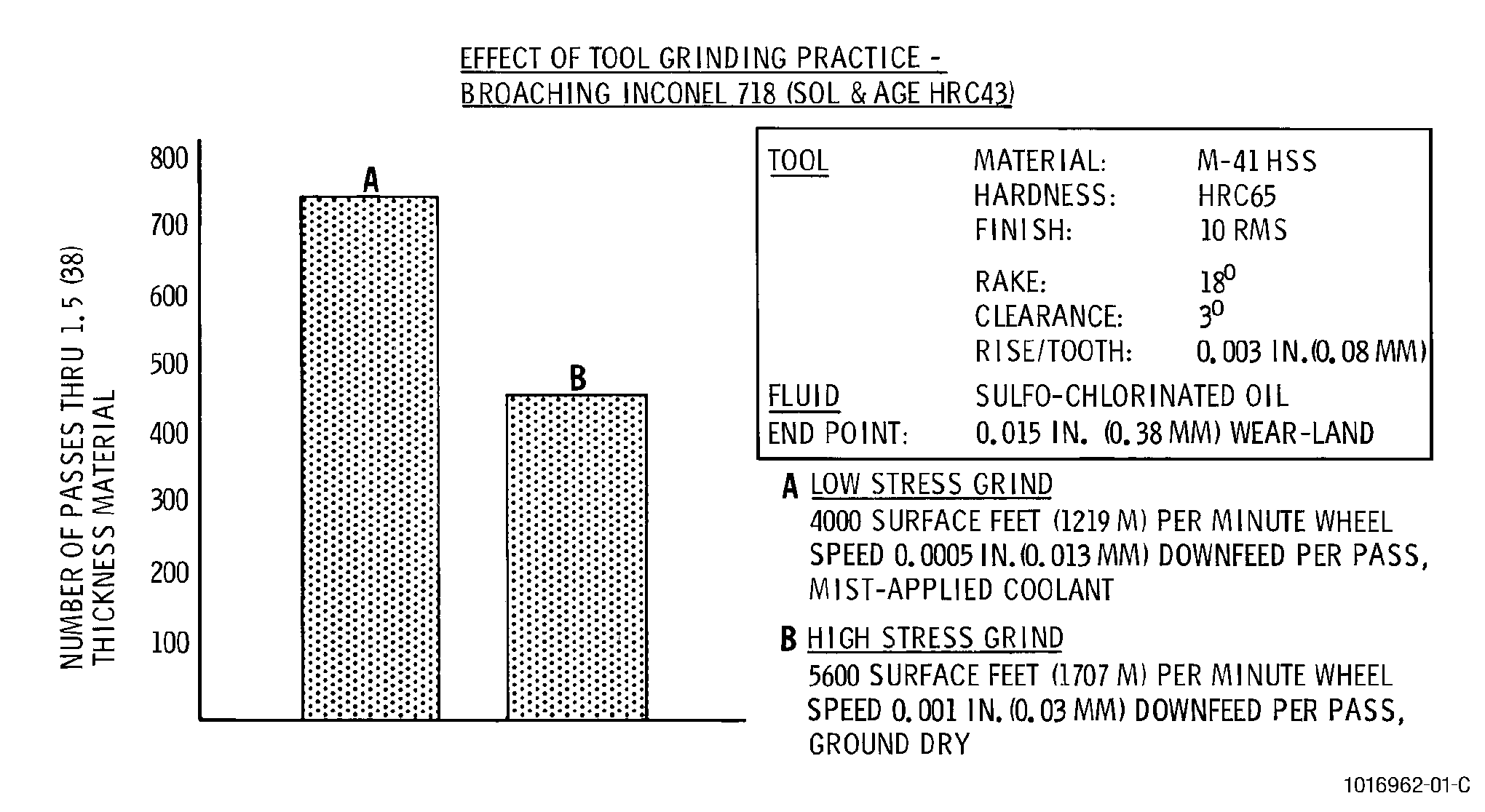
| (b) | Laboratory test have demonstrated the importance of grinding broach tools under low stress conditions which involve slower wheel speeds (4000 sfm reduced from 6500 sfm), lower downfeeds [0.0005 inch (0.13 mm)] reduced from 0.001 inch (0.03 mm) per grinding pass, and wet grinding instead of dry. Figure 13 shows the effect of grinding practices on tool life. Lowstress grinding conditions were responsible for an over 50 percent improvement in tool life. |
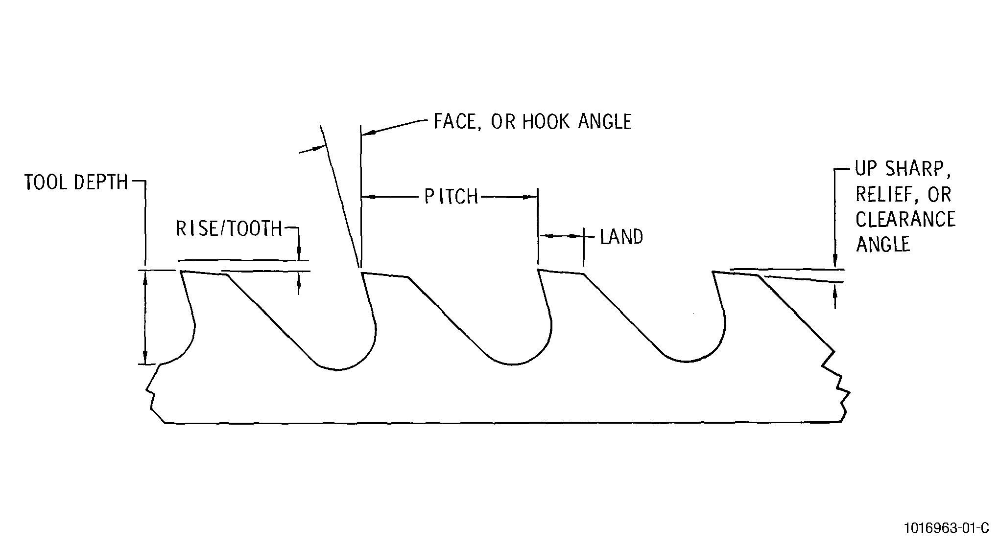
| (c) | Conventional high speed steel tool wear standard cannot be uniformly applied to broaching tools. Since dovetail slot tolerance is seldom wide enough to accommodate a 0.015 inch (0.38 mm) wear land and the size and surface finish will fall below drawing tolerances after a 0.005-0.006 inch (0.13-0.15 mm) wear land is reached, the 0.015 inch (0.38 mm) wear land end point is acceptable for rough cutters but not for finish form cutters. See Figure 14 for broach tool nomenclature. |
| (2) | Cutting fluids. See Figure 12. |
| E. | Procedure. |
| (1) | Broaching. |
| Broaching operations differ with the materials to be machined, the extremely close tolerances required, and the need for superior surface finishes. A laboratory test should precede the broaching of a new material in the shop. |
| (2) | Cutting fluid application. |
| The cutting fluid listed in Figure 12 is applied by flooding. Flooding application permits continuous flow of fluid to the cutting zone and is efficient in flushing away chips and in removing heat generated by the broach. |
| F. | Quality Assurance. |
| Check machined part to ensure that surface finish and dimensions agree with drawings. |
| 7 . | Drilling. |
| Subtask 70-00-03-800-046 |
| WARNING: |
|
| A. | General. |
| (1) | Drilling is a machining operation which generates round holes through the action of a tool, known as a twist drill, which normally has 2 cutting edges. Drilling common materials is accepted as simple in nature, however, the drilling of jet engine high temperature alloys has proven to be difficult because of work hardening materials. Drilling speeds are generally slower than those used for other operations because the cutting edge is in continuous contact with the metal when cutting, and the cutting edges are shielded from the flow and beneficial cooling action of the cutting fluid. |
| (2) | Successful drilling of jet engine alloys depends largely upon the construction of the twist drill, the rigidity of the machine to the fixtured part, the depth of the hole, and the effectiveness of the cutting fluid. |
| B. | Equipment. |
| There are many variations of the basic drilling machine but generally they are equipped with a base, column, powered spindle, and work table. The spindle is built to accept taper shank drills or drill chuck and is capable of running at a variety of speeds through the change of gears or of a belt/pulley arrangement. Either manual or power feed moves the spindle and/or work table up and down to accommodate the size of the workpiece. |
| C. | Materials. |
| (1) | Twist drills. |
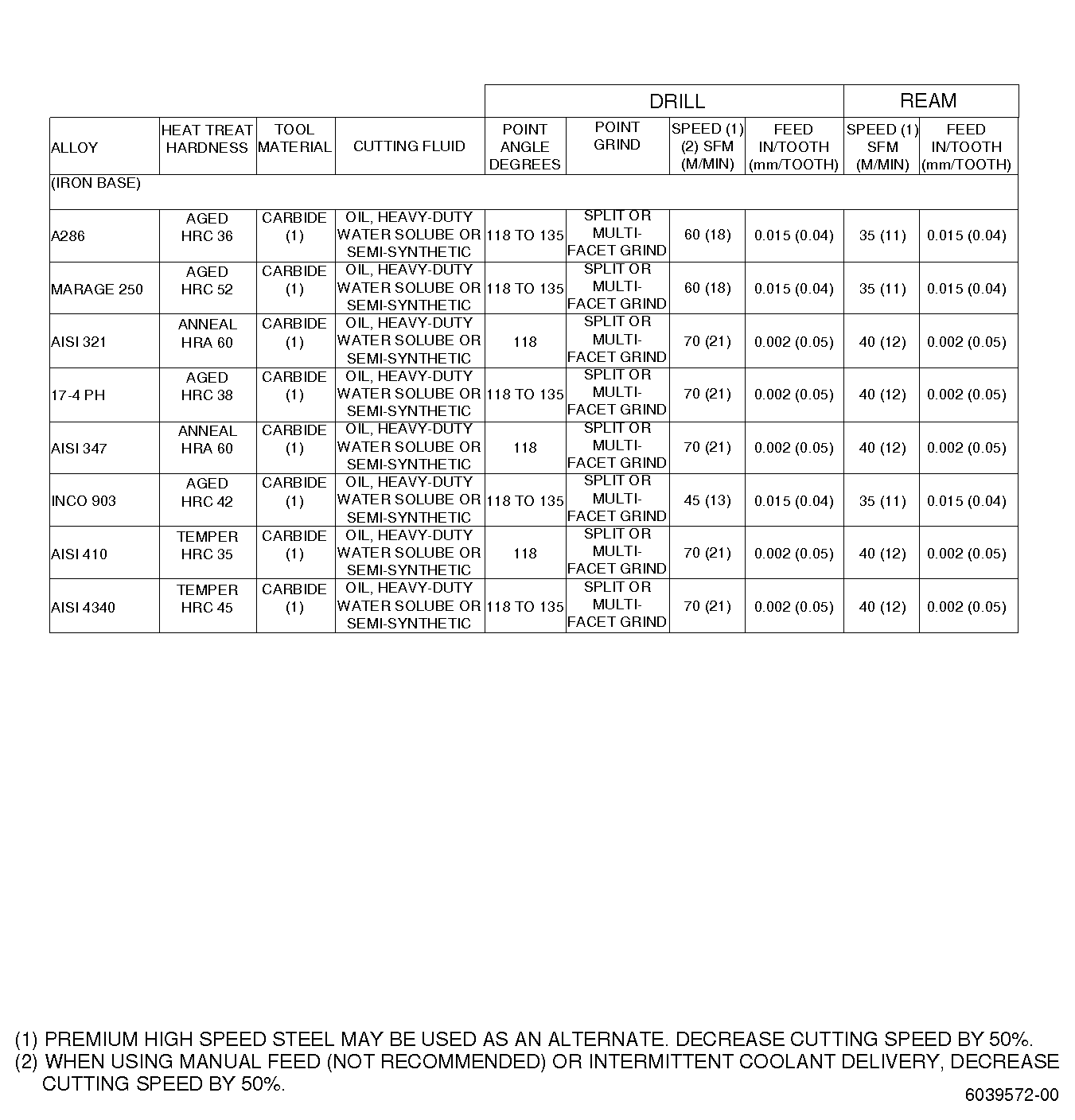
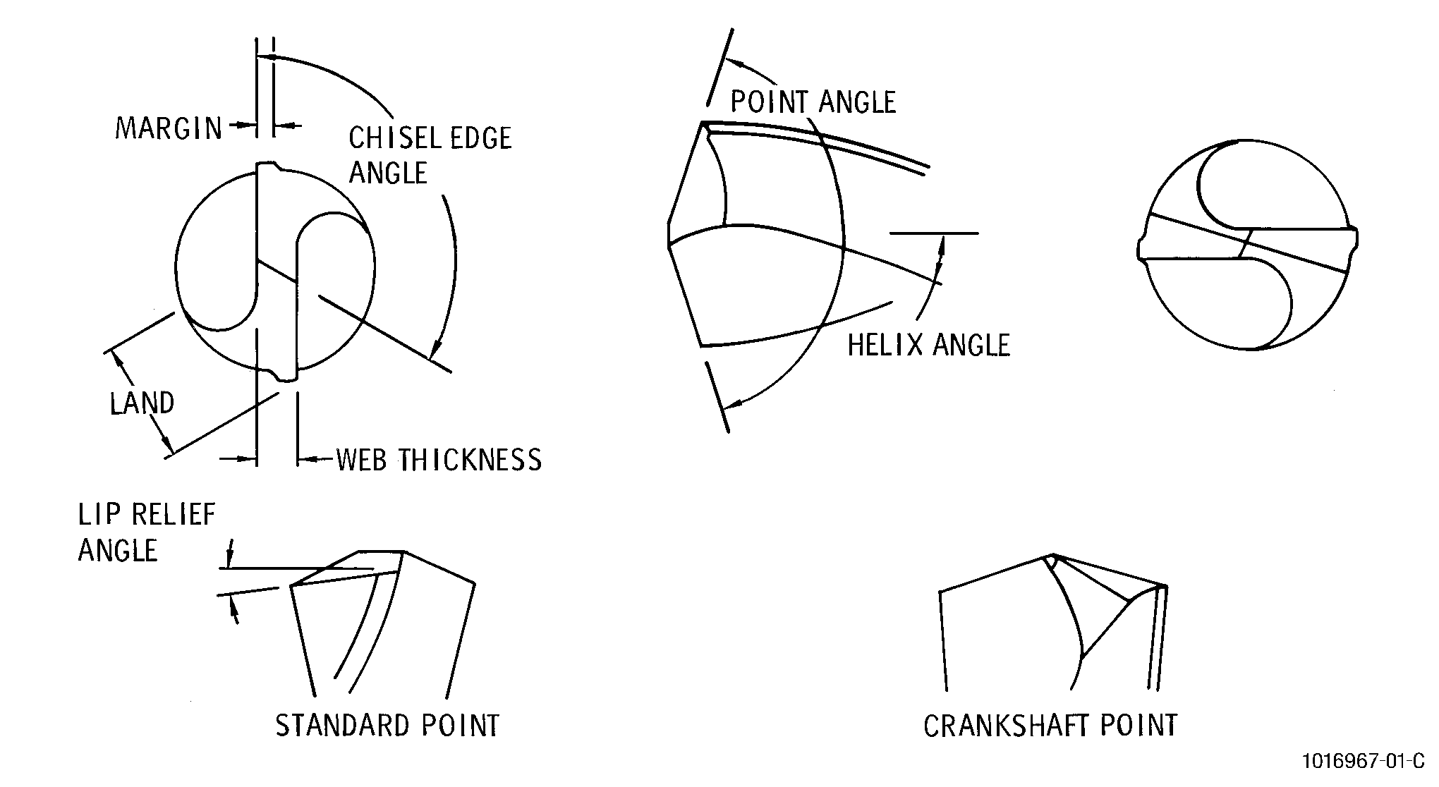
| The recommended twist drill material for use on particular alloys is shown in Figure 15. Twist drill point geometry is shown in Figure 16. |
| (2) | Cutting fluids. |
| The preferred cutting fluids for conventional drilling operations are water base with emulsifiable oils and sulfurized or chlorinated mineral oils. These fluids provide lubrication and coolant to prevent chatter and friction and to protect tool and workpiece from overheating. The normal application method is flooding. Recommended cutting fluids are listed in Figure 15. |
| D. | Procedure. |
| (1) | Drilling test data (see Figure 15) provides reliable parameters (speed, feed, cutting fluid, etc.) for drilling holes of approximately 0.25 inch (6.4 mm) diameter to a depth of 1 and 2 diameters. |
| (2) | One cause of poor tool life in deep hole drilling (holes exceeding 3 or 4 diameters) was found to be that the deeper the drill penetrated, the tighter the hole became. This tightening action generated more heat and shortened the tool life. |
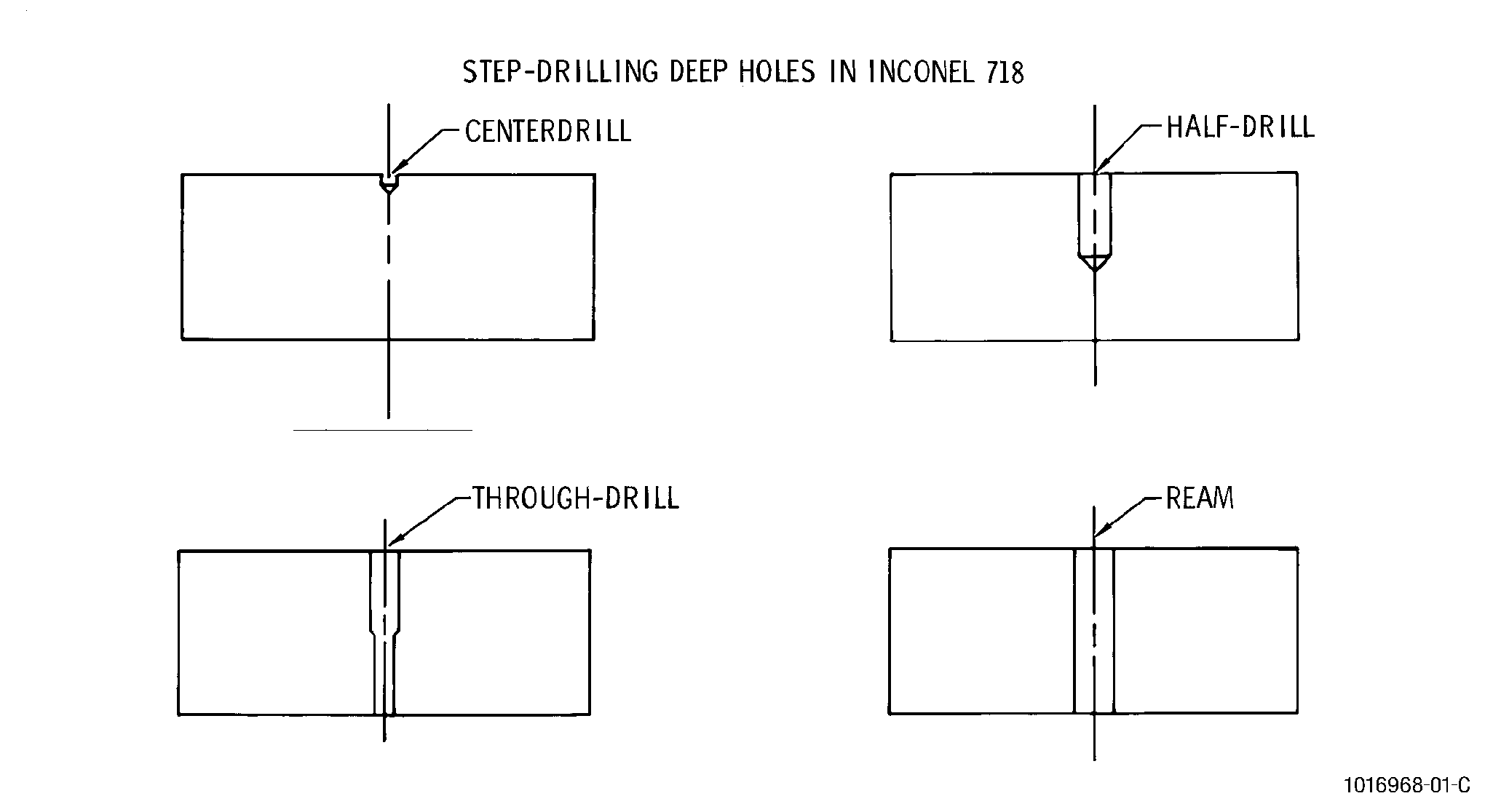
| (3) | One solution for drilling deep holes was found. Figure 17 shows a technique used in the deep hole drilling of Inconel 718. As a consequence of the 5/16 inch (7.94 mm) diameter holes having to penetrate more than 6 diameters [2 inch (50.8 mm)] material, the special step drilling technique became necessary. With this method, a hole is drilled half-way through the material with the nominal size drill, and is continued to completion with a drill slightly smaller than the one used for drilling the first half hole. The bore is then reamed to equal size throughout its length. This 2-step drilling technique improved drill life from 2 holes per drill sharpening to 40 holes. |
| (4) | Recommended guidelines to improve the success of the drilling operation are: |
| (a) | Ensure the drilling setup is rigid to prevent any vibration that could lead to work hardening. |
| (b) | When possible, plan for a single operation. With the exception noted above, it may be difficult to start a second operation because of work hardened surfaces caused by the first operation. |
| E. | Quality Assurance. |
| Check machined part to ensure that drilled holes are properly positioned and are of the correct diameter. |
| 8 . | Tapping. |
| Subtask 70-00-03-800-047 |
| WARNING: |
|
| A. | General. |
| Tapping is the machining operation whereby internal threads are cut into an already existing hole, using a multipoint thread tap. The hole can be made by drilling, boring, or casting and must be equal to or slightly smaller than the minor diameter of the thread. Taps, which are relatively fragile, are subjected to high torsional forces and the severe machining environment of entrapped chips. High temperature alloys that require small diameter tapping tend to magnify tapping difficulties. |
| B. | Equipment. |
| Radial drills, horizontal boring mills, turret drills, and other multi-purpose machines are used for tapping. Selection of the proper machine to be used for a particular tapping operation is based on the size, shape, and material of the part to be tapped; the number of related operations; the tolerances involved; the production rate; and the cost. Tapping recommendations must be based upon many factors. Individual setups may require experimentation to satisfy all variables. |
| C. | Materials. |
| (1) | Taps. |
| (a) | Most tapping required on jet engine components produces threaded holes of 1/4 inch (6.35 mm) to 5/16 inch (7.94 mm). Due to these sizes and the alloys these taps are used on, the taps appear comparatively weak. For tapping under 5/16 inch (7.94 mm) a 2 fluted tap with larger chip space is best. |
| For some applications, a 3 fluted tap holds size better. |
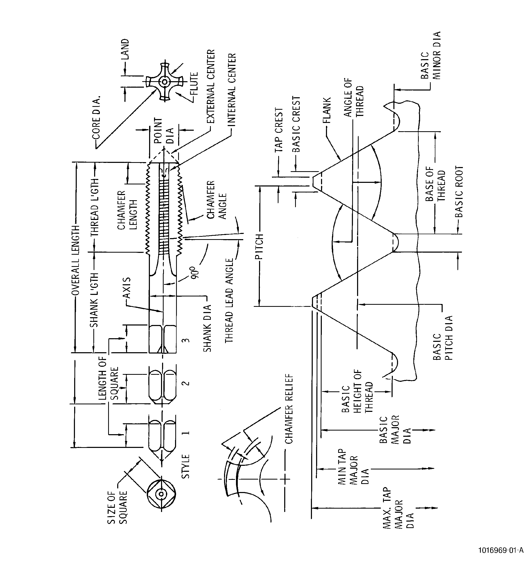
| (b) | General purpose high speed steel taps such as M2 and M7 HSS have proven satisfactory for the majority of applications. The tapping of superalloys may justify the use of more highly alloyed high speed steel. However, it is often more economical to use cheaper taps and discard them after short runs than to use costly taps with longer lives. See Figure 18 for tap nomenclature. |
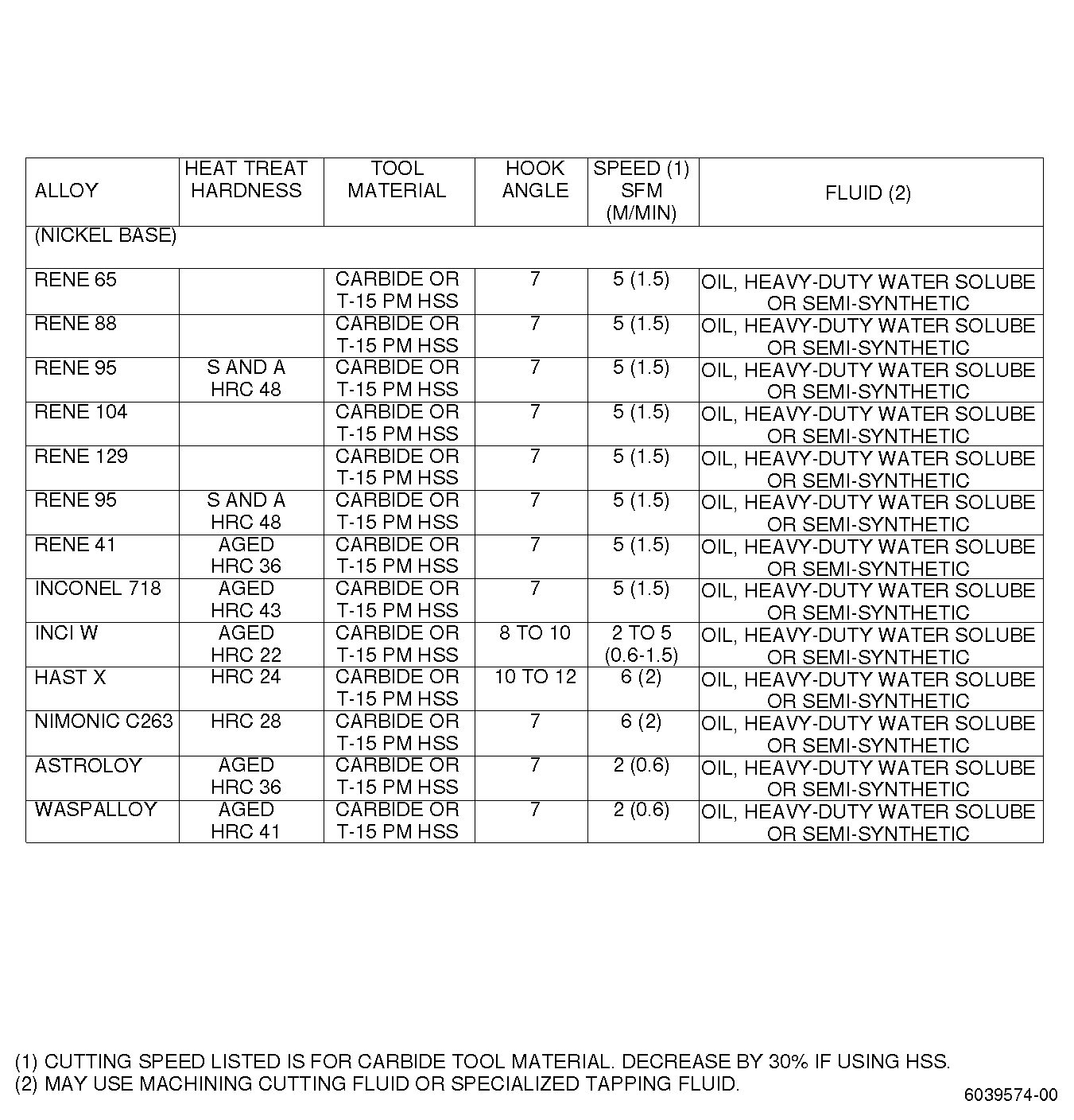
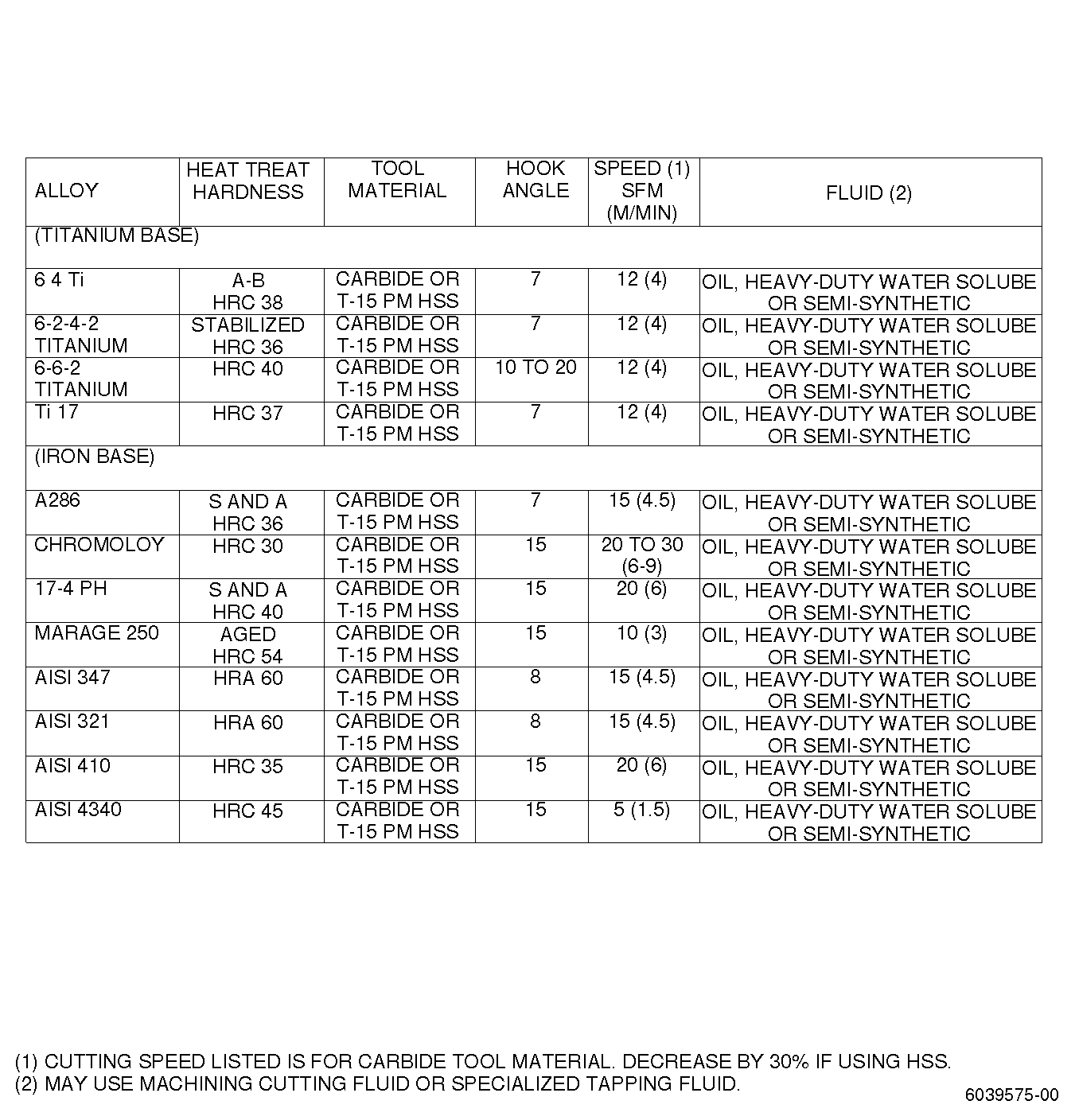
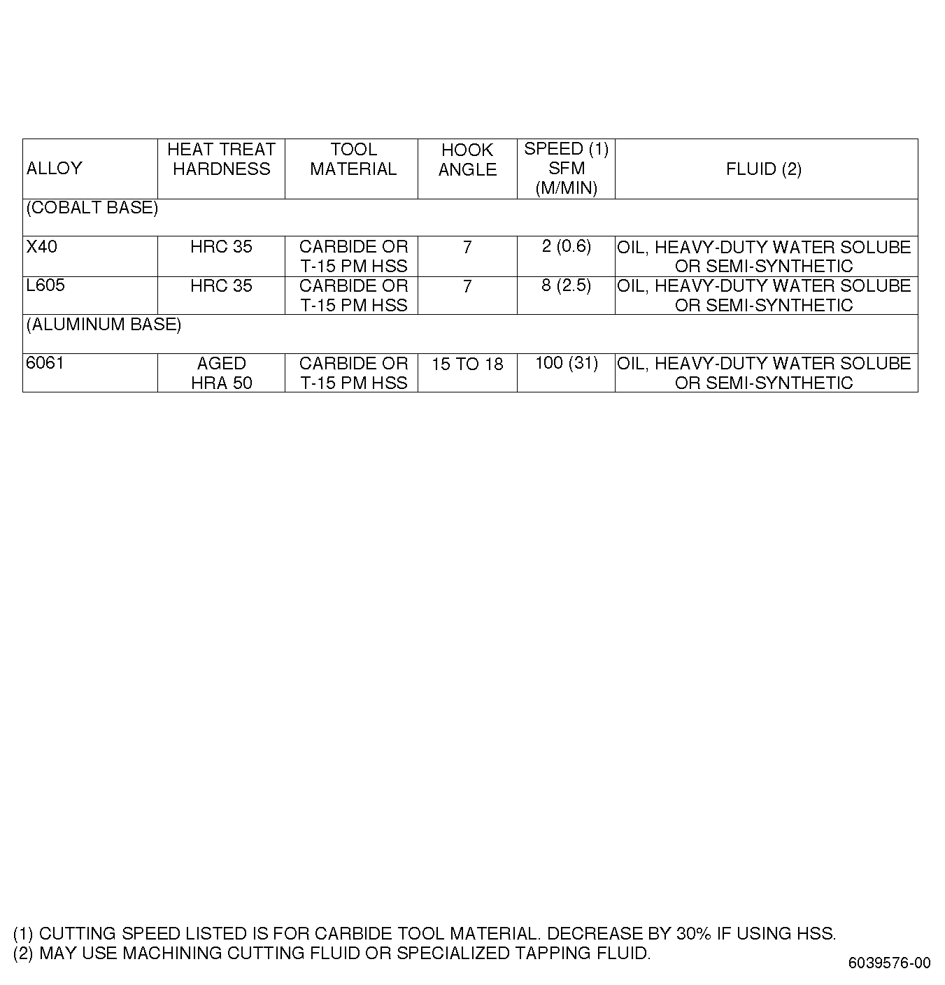
| (2) | Tapping fluids. See list in Figure 19. |
| D. | Procedure. |
| Useful initial guidelines for tapping a variety of materials are shown in Figure 19. Tapping fluids are applied by flooding. |
| E. | Quality Assurance. |
| Check tapped part to ensure threads are free of burrs and are of the correct geometry. |
| 9 . | Electrical Discharge Machining. |
| Subtask 70-00-03-800-048 |
| WARNING: |
|
| A. | General. |
| (1) | Electrical discharge machining (EDM) is the machining operation which removes electrical conductive material utilizing high frequency electrical sparking to melt and/or vaporize the material in a controlled manner. This process is performed in a dielectric bath, normally transformer oil or paraffin oil, with specially shaped electrodes which discharge at high frequencies from a capacitor bank. |
| (2) | EDM is a simple method for producing holes and depressions, of almost any shape, in electrically conductive materials too hard or too brittle to be machined by conventional machinery. |
| (3) | EDM can normally achieve a machining accuracy of ±0.002-0.004 inch (0.05-0.10 mm) and surface finishes in the range of 125-500 micro inches (3.2-12.5 microns). |
| (4) | The thermal effects of EDM causes the machined surface to be altered from the base material. The thermal effects change not only the surface structure and material characteristics but also can create minute cracks which can progress into the base material. The depth of the alteration can vary from 0.001-0.005 inch (0.03-0.15 mm) depending upon whether the part is being rough or finish machined. The thickness and hardness of the altered layer increase with increased current. To minimize this formation lower current, higher frequencies, and a clean dielectric are required. |
| (5) | For parts that are fatigue-stressed, the altered layer must be removed, either by chemical or mechanical means. Without this removal, electrical discharge machined parts lose 30-50 percent of their fatigue strength as compared with conventionally machined parts. |
| (6) | Low alloy steels and martensitic stainless steels require passivation processing after EDM and after removal of the altered layer when removal is done by chemical means. |
| (7) | EDM can be used only when specified in the Engine/ Shop Manual. |
| B. | Equipment. |
| (1) | The majority of electrical discharge machines are of the ram type which utilize a workhead moved by a hydraulic cylinder. Machines using quill-type workheads are also available but are used normally for smaller work. |
| (2) | Both ram and quill machines have servo control for tool advance to maintain the constant spark gap. The servo input signal is the differential voltage between the selected reference voltage and the actual voltage across the gap. This voltage differential is amplified and the hydraulic control system advances the tool. A short circuit across the gap causes the servo to reverse the tool motion until control is restored. |
| C. | Materials. |
| (1) | Electrodes. |
| (a) | Electrodes are selected in accordance with: workpiece finish, geometry, tolerance, material removal rate, wear ratio, quantity, and cost. |
| (b) | Electrode materials are: brass, copper, copper graphite, copper tungsten, graphite, tungsten wire, and tungsten carbide. |
| (2) | Dielectric fluids. |
| The main features of a dielectric fluid are: |
| (a) | It should retain its insulating properties until the striking of the spark occurs, i.e., when each pulse reaches the breakdown voltage; then, it should act as a good conductor. |
| (b) | It should return to its initial insulating state when the electrical discharge is completed, i.e., between pulses, a voltage should not exist in the electrode-to-workpiece gap. |
| (c) | It should act as a flushing agent to remove particles of material, resulting from the EDM process, out of the machining gap. |
| (d) | It should act as a cooling agent for both the electrode and the workpiece. |
| NOTE: |
|
| D. | Procedure. |
| (1) | Ensure that part is free of any scale or any other surface contamination prior to machining. |
| (2) | Ensure that part is connected to the positive side of the DC potential and that the electrode is attached to the negative side. |
| (3) | After the machining operation, clean the part of all dielectric oil. |
| E. | Quality Assurance. |
| (1) | For parts on which altered layer must be removed, check for freedom of EDM machining marks after completing mechanical or chemical rework. |
| (2) | Check for abnormal overheating indications. |
| (3) | Check that part shows no cracks, pits, etc. |
| (4) | Allowable limits for altered layer, cracks, pits, etc., must be specified in the Engine/Shop Manual. |
| 10 . | Electro-Chemical Machining. |
| Subtask 70-00-03-800-049 |
| WARNING: |
|
| A. | General. |
| (1) | Electro-chemical machining (ECM) is the machining process which removes metal by controlled anodic dissolution through the passage of direct current in a flowing electrolyte, with the workpiece being the anode and the electrode is the cathode. |
| (2) | ECM can be used to machine extremely hard materials especially the super alloys. ECM can be used for many different operations such as face milling, drilling holes of any shape, trepanning, contour surface forming, deburring, and polishing. Because of the high costs involved in tooling and set up, the ECM process is best suited for production work. |
| (3) | The electrolyte is pumped under pressure, 100-300 psi (690-2070 kPa) and flows at a rate of 50-200 ft/sec (15-61 m/sec) between the workpiece and the electrode. This cutting gap can vary from 0.001-0.030 inch (0.03-0.76 mm). The current density determines the feed rate which can vary from 0.010-0.25 inch (0.25-6.35 mm) per minute. The higher the feed rate the better the surface finish. During operation, the electrolyte, usually a saline solution, is maintained at a temperature of between 75-150°F (24-66°C). |
| (4) | The entire electrolytic cell is enclosed in a flow chamber or box sealed to permit the tool to be fed into the workpiece and prevent leakage of the electrolyte. Suspended solids are removed and the electrolyte is circulated for reuse. There is no tool wear. |
| (5) | Safety precautions must be maintained in the use of ECM equipment and materials. Ventilation of mists, vapors, and dusts should be provided. Wearing of protective gloves and face shields can be required for handling chemicals. Sound operating procedures must be worked out to minimize the likelihood of short circuits which might cause explosions. |
| (6) | ECM can be used on all electrically conductive materials with machining tolerances ranging from 0.003 inch (0.08 mm) to 0.010 inch (0.25 mm) depending upon the complexity of the part. ECM generated surface finishes are generally lower than 200 micro inches (5 microns) for titanium alloys and lower than 100 microinches (2.5 microns) for the other materials. |
| (7) | ECM does not create compressive stresses in machined surfaces like those generated by mechanical machining. This results in machined surfaces which have fatigue strengths 20 to 30 percent less than mechanically machined parts. Surface conditioning by shotpeening or other methods may be required to raise the fatigue strength. |
| B. | Equipment. |
| ECM equipment must have servomechanisms to advance the tool; an electrolyte system which can pump, filter, and maintain the electrolyte at the proper temperature; and a control system that maintains current density and cutting gap. In addition the machine must be rigid enough to resist the high pressure of the pumped electrolyte which tends to force the tool and workpiece apart. |
| C. | Materials. |
| (1) | Electrodes. |
| The electrodes or tools are of critical importance to successful ECM operations. These tools are normally empirically designed, although basically the tool is required to have the needed stiffness, machinability, electrical and thermal conductivity, and chemical resistance to the electrolyte. Most ECM tools are made of copper, brass, stainless steel, or titanium. |
| (2) | Electrolytes. |
| Electrolytes have 3 functions: they carry the current across the cutting gap, carry away the dissolved material, and act as a coolant for both the tool and the workpiece. Electrolytes are selected for particular processes and materials. The most common electrolyte used with titanium and superalloys is NaCl in a variety of concentrations. Other electrolytes are KCl and NaNO. |
| D. | Procedure. |
| (1) | Prior to machining, parts must be degreased and freed of any scale or of any other surface contamination. |
| (2) | At completion of ECM machining, parts must be rinsed in water and cleaned to remove electrolyte and any contaminants resulting from machining. |
| E. | Quality Assurance. |
| Parts must be inspected to ensure that pitting and inter-granular attack (IGA) does not exceed Engine/Shop Manual limits. |