| COMMERCIAL ENGINE STANDARD PRACTICES MANUAL | Dated: 12/04/2018 | |
| SPM 70-10-00 ASSEMBLY AND DISASSEMBLY TECHNIQUES | ||
| COMMERCIAL ENGINE STANDARD PRACTICES MANUAL | Dated: 12/04/2018 | |
| SPM 70-10-00 ASSEMBLY AND DISASSEMBLY TECHNIQUES | ||
| TASK 70-10-00-800-009 |
| 1 . | General. |
| Basic disassembly and assembly practices and techniques are covered in this section. Careful handling of engine parts and proper use of special tools and fixtures specified in this manual are essential. Damage to engine parts, manufactured to close tolerances, can cause serious engine malfunctions. |
| 2 . | Cleanliness. |
| Subtask 70-10-00-800-091 |
| CAUTION: |
|
| A. | It is important that the assembly shop be clean and dust free, to prevent foreign material from entering the engine or its subassemblies. A major cause of premature engine removal is foreign object damage (FOD). It is recommended that FOD containers be kept at or near each work area. |
| B. | All parts should be inspected for cleanliness before being installed. |
| C. | Mating flanges, fittings, and couplings should be wiped clean to ensure obtaining a good seal. |
| D. | Hands and gloves must be clean when handling machined surfaces. |
| E. | After performing any work, the area should be thoroughly inspected for loose parts, rags, tools, and materials. |
| 3 . | Overall Assembly. |
| Subtask 70-10-00-800-092 |
| A. | Before starting disassembly or assembly operations, consult the Engine/Shop Manual. The applicable procedure is described in logical step-by-step sequence. Always read the complete procedure; be sure you understand. It is better to stop and ask than to continue on and cause unnecessary work and/or damage. |
| B. | Lift heavy parts with proper fixtures and hoist to prevent damage to parts or injury to personnel. |
| C. | Perform operations using the tools specified in the engine manual. Maintain tools in good condition and use special tools only for the use intended. |
| D. | Metal hammers and drifts (including brass) shall not be used to force any part of the engine. To prevent damage, plastic, nylon or rawhide-faced hammers and drifts may be used for driving operations, if necessary. |
| E. | Complete each phase of assembly before proceeding to the next phase. Do not leave bolts untightened or fasteners unlocked unless specified in the Engine/Shop Manual. |
| F. | Do not remove plugs or coverings from parts until part is to be installed. |
| G. | When installing or removing body-bound bolts, tap them straight through holes. Do not turn them. |
| H. | During assembly, align matchmarks on all parts which are marked during disassembly or subassembly. |
| I. | Do not mix plated and unplated hardware. Do not use silver or cadmium-plated tools or hardware on titanium parts. Plating contains small quantities of chlorine salts which are harmful to titanium. |
| NOTE: |
|
| WARNING: |
|
| CAUTION: |
|
| J. | Accessories, tubes, and hoses may have oil or fuel in them at time of removal. Drain these fluids from accessory being removed, and cap all connecting hoses or tubes. |
| K. | Lubricate all gears and splines with oil before installing them, unless otherwise specified. |
| NOTE: |
|
| L. | Prior to installation of any part, a quick visual check should be made and any obvious discrepancies noted and reported, so that corrective action can be taken. |
| M. | Do not use external engine piping as a ladder or hand-hold while performing maintenance. Serious engine damage could result. Use only authorized work stands and platforms. |
| N. | The engine should not be used as a shelf for holding tools or parts while work is being performed. |
| CAUTION: |
|
| O. | A process should be in place to track and account for all parts released to support the planned assembly and to track all removed protective covers. |
| NOTE: |
|
| NOTE: |
|
| 4 . | General Assembly Precautions. |
| Subtask 70-10-00-800-093 |
| CAUTION: |
|
| A. | Do not handle bearings with the bare hands or with any device that could cause contamination or scarring. Use clean rubber or plastic gloves. During assembly of bearings do not apply force to balls or rollers. Refer to TASK 70-14-00-620-003 , Handling of Bearings. |
| B. | Use new cotter pins, lockwashers, tabwashers, spring washers, preformed packing (O-rings), and gaskets throughout assembly. All safetywiring and safety cable installation must be done in accordance with the instructions in TASK 70-11-01-400-005, Safety Wire Procedure, and TASK 70-11-02-400-006, Safety Cable Procedure. |
| CAUTION: |
|
| C. | Do not use bolts, screws, or nuts which have damaged threads. Check all beam-type (pinched castellated) and elliptically formed self-locking nuts for locking quality, using the procedure in Step 9 of TASK 70-51-00-400-004, Tightening Practices and Torque Values. |
| D. | Inspect all blind tapped holes and remove any foreign material before installing studs or screws. |
| E. | The bolts and screws on the engine require a definite tightening torque. Specific torque values are defined in the Engine/Shop Manual. Tighten sets or groups of fasteners holding a single part by using a staggered or diametrically opposite sequence, and do not tighten to final torque at the first drawdown. |
| F. | When tightening threaded parts that are not rigidly supported, or that are attached to parts that cannot withstand full torque without bending or twisting, use a second wrench and apply countertorque to support the mating part. |
| G. | Use fiber or plastic blocks to protect engine parts being assembled by means of an arbor press. |
| H. | Tube and Tube Connectors. |
| CAUTION: |
|
| (1) | Check cleanliness, especially on seals and threaded areas. |
| (2) | Inspect the tube assembly to ensure satisfactory general condition and that no handling damage has occurred. |
| (3) | Fit the tube assembly without application of force; however, a slight elastic distortion is allowed for engagement of connectors. |
| I. | Use of motor-driven hydraulic pumps to operate hydraulically actuated special support equipment other than torque multipliers is not recommended. Equipment damage can result from improper power application. Use hand-operated hydraulic pumps to operate hydraulically actuated special |
| support equipment such as pushers or pullers, unless otherwise specified. |
| J. | Removal of parts (Heating and Chilling). |
| (1) | Unless specified differently, use these procedures to make the disassembly easier and to decrease the risk of damage during disassembly. |
| (2) | Heating for part removal. |
| NOTE: |
|
| (a) | Wear gloves and protective clothes and quickly assemble the hot parts. |
| (b) | Use one of the procedures that follow to increase the temperature of the outer diameter parts to a maximum of 250°F (121°C) (unless specified differently): |
| 1 | Put the part in an oven and gradually increase the temperature of the part to the correct temperature, or |
| 2 | Wrap the part in a heating blanket and gradually increase the temperature of the part to the correct temperature, or |
| 3 | Use the heater and controller as specified in the Engine/Shop Manual. |
| 4 | Use of a heat gun or an open flame (if permitted by the local environmental health and safety practices) is approved if you use appropriate temperature sensors to monitor the gradual and even distribution of heat to the correct temperature. |
| (c) | Work quickly to decrease the temperature transfer between hot and cold parts. |
| WARNING: |
|
| (3) | Chilling for part removal. |
| NOTE: |
|
| (a) | Wear gloves and protective clothes and quickly disassemble the frozen parts. |
| (b) | Use dry ice to chill the inner diameter parts. |
| (c) | Work quickly to decrease the temperature transfer between the hot and cold parts. |
| WARNING: |
|
| K. | Installation of the parts (heating and chilling). |
| (1) | When it is necessary to install an engine part (other than engine bearings) that has a tight fit, it is permissible to heat or chill the surrounding metal to make the installation easier. |
| (2) | Unless specified differently, use these heat and chill procedures to make the assembly easier and to decrease the risk of damage. |
| (3) | Heating for part installation. |
| NOTE: |
|
| (a) | Wear gloves and protective clothes and quickly assembly the hot/cold parts. |
| (b) | Use one of the procedures that follow to increase the temperature of the outer diameter of the parts to a maximum of 250°F (121°C) (unless specified differently): |
| 1 | Put the part in an oven and gradually increase the temperature of the part to the correct temperature, or |
| 2 | Wrap the part in a heating blanket and gradually increase the temperature of the part to the correct temperature, or |
| 3 | Use the heater and controller as specified in the Engine/Shop Manual. |
| 4 | Use of a heat gun or an open flame (if permitted by the local environmental health and safety practices) is approved if you use appropriate temperature sensors to monitor the gradual and even distribution of heat to the correct temperature. |
| (c) | Work quickly to decrease the temperature transfer between hot and cold parts. |
| WARNING: |
|
| (4) | Chilling for part removal. |
| NOTE: |
|
| (a) | Wear gloves and protective clothes and quickly disassembly the frozen parts. |
| (b) | Use dry ice to decrease the temperature of the inner diameter parts. |
| (c) | Work quickly to decrease the temperature transfer between hot and cold parts. |
| (5) | The parts must be fully seated to each other before they get to room temperature. |
| (6) | Before you torque any retaining nut or fasteners, make sure that the parts are approximately at room temperature. |
| 5 . | Electrical Bonding Straps. |
| Subtask 70-10-00-800-094 |
| A. | Electrical bonding strap contact surfaces shall be prepared by removing all anodic film, grease, paint, lacquer, or other high-resistance material from an area at least one and one-half times the bonding surface contact area. |
| 6 . | Marking of Parts. |
| Subtask 70-10-00-800-095 |
| A. | Parts or assemblies designated as matched will be maintained as matched sets throughout the maintenance process. Set numbers, part numbers, and serial numbers will be protected during cleaning or rework to prevent removal. When identification is removed or is no longer legible, the item must be re-marked per the original marking method and location for the part as specified on the applicable drawing. |
| B. | Permanent Marking. |
| (1) | Permanent marking of parts should be done in the area of lowest stress as specified on applicable drawing. Methods are listed in order of preference (unless otherwise specified). Electric etch is not approved. |
| (a) | Electro-chemical etch - preferred. |
| (b) | Vibropeen - acceptable. |
| (c) | Metal stamp - special use only. |
| C. | Temporary Marking. |
| CAUTION: |
|
| CAUTION: |
|
| (1) | Refer to TASK 70-16-00-350-001, Marking Practices, for acceptable methods and materials. |
| 7 . | Correction of Leaks. |
| Subtask 70-10-00-800-096 |
| CAUTION: |
|
| A. | Disassemble connection. |
| B. | Discard seal, gasket, or preformed packing (O-ring), if present. |
| C. | Inspect mating surfaces for contamination, scratches, dents, or other surface defects. |
| D. | Inspect threaded fasteners for thread damage and assure that fasteners seat properly when tightened to specified value. |
| E. | Replace nonserviceable parts and assemble connection using new seals, gaskets, or preformed packings (O-rings), as required. |
| 8 . | Unpacking and Repacking. |
| Subtask 70-10-00-800-097 |
| A. | The following general instructions apply during unpacking and repacking to minimize possible part damage and contamination. |
| (1) | Initially remove only that portion of the pack necessary to mount the part. Where possible, remove the remainder of the pack, including protective closures, one at a time as each connection (fluid, air, or electrical) is made. |
| (2) | Retain protective closures and reusable pack components for repack purposes. |
| (3) | Install closures on each connection (fluid, air, or electrical) as it is disconnected. |
| (4) | When possible, repack part for storage or shipment using the same pack in which replacement part was received. |
| (5) | When original pack components are not available, use locally available packing materials and container to pack the part. Make sure that all ports, openings, connections, and mating surfaces are capped or covered and that the part is protected from potential handling and environmental damage. |
| 9 . | Jackscrews. |
| Subtask 70-10-00-800-098 |
| A. | When using jackscrews to remove components, do not bend flanges or strip threads. Lubricate jackscrews with engine oil before installing. Turn jackscrews evenly and in small increments. Always check jackscrews for burrs or rough edges before using. Remove all burrs or rough edges. Do not allow components to fall free as jackscrews are tightened. |
| B. | Jackscrew holes are often in flanges only thick enough to accept 3 or 4 threads. If regular bolts are used as jackscrews, the tips must be blunt and polished. The ends of most standard bolts are chamfered, and the first couple of threads are missing or incomplete. These should not be used as jackscrews without modification, since one or 2 threads will engage, and the threads in the flange are likely to strip. Jackscrews, frequently designed as such and identified as special tools, are not chamfered and full thread engagement will occur. |
| If specially manufactured jackscrews are not available and must be locally manufactured, be sure that the ends are ground to remove the chamfers and the incomplete threads, so that a maximum number of threads may be engaged. |
| 10 . | Protective Closures and Caps. |
| Subtask 70-10-00-800-099 |
| A. | Prevent foreign material from lodging in drilled passages, fuel lines, oil lines, air lines, and open engine ports. Machined surfaces must be properly protected to prevent damage. |
| B. | Wrap precision parts and cap or plug all openings and connections. It is most important that all engine parts be kept clean and free of corrosion. All instructions which require special handling of parts must be followed without exception. |
| C. | Accessories, tubes, and hoses may have oil or fuel in them at time of removal. Drain these fluids from accessory being removed, and cap all connecting hoses or tubes - do not use tape. |
| D. | Do not remove plugs, caps, etc., until part is ready for assembly. Check both seating surfaces for removal of plugs, etc., prior to assembly. |
| 11 . | Gaskets and Preformed Packing (O-Ring) Seals. |
| Subtask 70-10-00-800-100 |
| WARNING: |
|
| WARNING: |
|
| WARNING: |
|
| A. | Calcium Gluconate Gel 2.5 percent is prepared by mixing 3.5 grams of calcium gluconate powder with a 5 ounce tube of surgical water-soluble lubricant (e.g., KY Lubricating Jelly, Johnson & Johnson) or by mixing 1 standard ampule (10 ml, 10 percent) of USP calcium gluconate with 1 ounce of water-soluble lubricant. The shelf life of the gel has not been determined. Storage of the gel has limitations and refrigeration may help. |
| B. | Gaskets and Preformed Packing (O-ring) seals shall not be reused unless otherwise specified. |
| CAUTION: |
|
| CAUTION: |
|
| CAUTION: |
|
| C. | Gaskets and Preformed Packing (O-ring) seals shall be lightly lubricated with petrolatum soft C02-033 , petroleum jelly C02-008 , grade 1010 oil C02-021 , grade 1005 oil C02-091 , engine lubricating oil C02-019 , or engine lubricating oil C02-023 before the installation unless otherwise specified. If the preformed packing (O-ring) requires a tacky type assembly fluid to perform the function of retaining the preformed packing in the seal groove, use assembly fluid C02-007 or O-ring lubricant C02-090 to minimize the risk of damage during assembly. Make certain parts are properly seated in the special case of a fitting with a jamnut and preformed packing (O-ring). |
| NOTE: |
|
| 12 . | Tubes. |
| Subtask 70-10-00-800-101 |
| A. | As tubes are installed, tighten all end fittings and clamps finger-tight. After a complete system is installed, tighten clamps first, then end fittings. |
| B. | Maintain clearance between tube and each adjacent part. |
| C. | Coupling nuts shall thread freely by hand. |
| D. | Mating flanges on tube shall seat flush. |
| E. | If tubes are reworked, bend radii shall not be less than twice the tube diameter and bend angle shall not be changed by more than 3 degrees. No kinks or wrinkles are allowed. |
| F. | Do not bend at fitting or weld areas. |
| G. | Original bends in tube may be bent in the same direction; no reverse bending is allowed. |
| H. | Bend tube in existing straight sections if possible. |
| I. | Use bending tools on tubes, one inch (25.4 mm) or more in diameter, to prevent tube from collapsing. |
| J. | On those couplings where sealant is required, allow sealant to dry 10 minutes minimum before assembly. Wipe off any sealant on inside of tube with a clean cloth and water. Do not allow sealant to enter air systems. |
| 13 . | Clamps. |
| Subtask 70-10-00-800-102 |
| A. | Chafing of hoses and tubes must be avoided. Clamp parts loosely in place, shift the hoses around to obtain best clearance, then tighten clamps. Clamps must be proper size for piping to permit slippage during engine thermal growth. See Figure 1. |
| 14 . | Electrical Cables and Connectors - Disconnect and Connect. |
| Subtask 70-10-00-800-103 |
| NOTE: |
|
| A. | Connector disconnect. |
| (1) | Loosen the electrical connector by hand or by using soft-jawed pliers. |
| (2) | Visually inspect the connector and the receptacle for obvious signs of damage, bent pins, or corrosion. |
| (a) | If damage is found, repair or replace the connector or receptacle. |
| (3) | Install protective caps on the connector and the receptacle. |
| NOTE: |
|
| B. | Electrical Cable Installation. |
| (1) | During electrical installation, adjust the cable through the clamps to get the smoothest and largest radius. |
| (2) | Avoid sharp bends, twists, and kinks. |
| (3) | Ensure that a minimum clearance of 0.125 inch (3.18 mm) is maintained between electrical cables and any component other than hoses or other electrical cables. |
| NOTE: |
|
| CAUTION: |
|
| C. | Connect the electrical connector. |
| (1) | Remove the protective caps from the connector and the receptacle. |
| (2) | Inspect the electrical connector pins for straightness before connecting. |
| (3) | Ensure that the seal ring is present in the coupling nut of the electrical connector and that it is serviceable. If the seal is not present or is damaged, replace as follows: |
| (a) | Remove the unserviceable seal. |
| (b) | Engage the new seal over the barrel of the connector. |
| CAUTION: |
|
| (c) | Push the seal to the seated position against the internal shoulder in the connector using a mating connector or a blunt screwdriver. |
| (4) | Engage the electrical connector with the receptacle by hand. |
| (5) | Move the backshell assembly from side to side while turning the knurled ring of the electrical connector until the electrical connector is fully seated, finger-tight. |
| (6) | If the knurled ring of the electrical connector is accessible, use soft-jawed pliers to tighten the knurled ring of the electrical connector beyond finger-tight, 20 degrees maximum. |
| (7) | If the knurled ring of the electrical connector is not accessible, tighten as follows: |
| (a) | Tighten the knurled ring of the electrical connector with your hand, and then use soft-jawed pliers to tighten the connector until the soft-jawed pliers slip. This will be approximately 1/8 turn more than hand-tight. |
| (b) | Check the connector backshell assembly for side to side movement. If movement is present, disconnect the connector and reconnect, referring to paragraphs 14.A. through 14.C. |
| (8) | Safety-wire the connector if specified in the assembly procedure. |
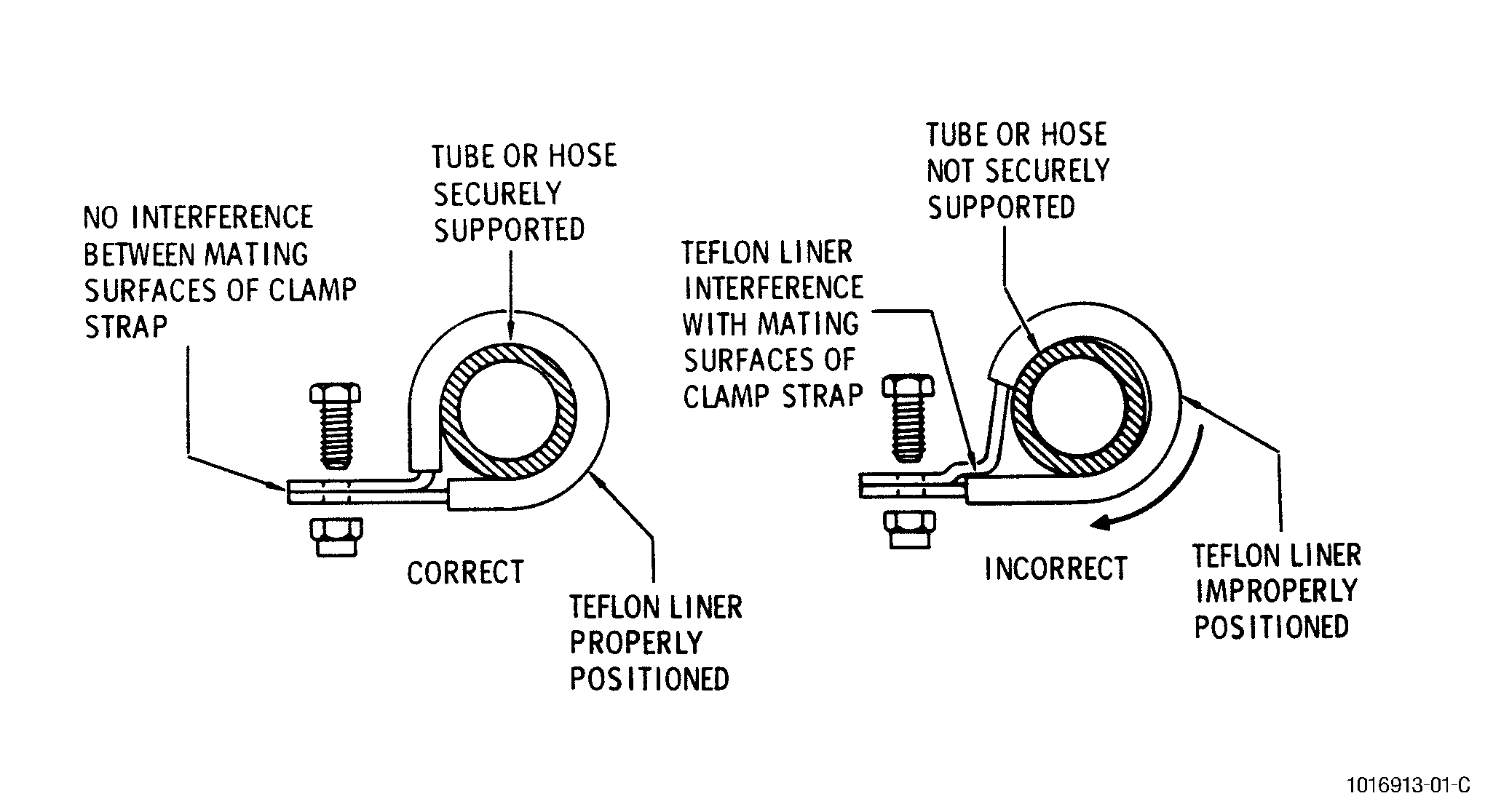
| 15 . | Hoses. |
| Subtask 70-10-00-800-104 |
| A. | No hose should be bent, especially when the parts are cold, because of possible damage to the Teflon liners. Kinked hoses must not be used. During installation, be sure that no hose is twisted or stretched; never over-tighten connectors. When hoses are removed, cap the open ends. Do not use tape. See Figure 2. |
| B. | Fluid fittings shall be tightened gradually to the required torque value, backed off 0.25 turn then tightened again. Do not attempt to correct a leak by excessive tightening. Always use two wrenches when tightening swivel coupling nuts on hoses, tubes, or fittings. Hold the stationary part with one wrench while applying torque with second wrench. Apply lube oil between tube-hose coupling nut and ferrule prior to tightening. See Figure 2. |
| C. | Preformed hoses or hoses of large diameter shall not be bent or straightened. When hoses are removed, cap the open ends. Do not use tape. |
| D. | Before installing preformed hoses, visually inspect the hose interior to assure that the Teflon lining has not been damaged. Replace the hose if the lining has been damaged. |