| COMMERCIAL ENGINE STANDARD PRACTICES MANUAL | Dated: 02/21/2020 | |
| SPM 70-13-01 ACCEPTABILITY LIMITS FOR FORMED RIVETS | ||
| COMMERCIAL ENGINE STANDARD PRACTICES MANUAL | Dated: 02/21/2020 | |
| SPM 70-13-01 ACCEPTABILITY LIMITS FOR FORMED RIVETS | ||
| TASK 70-13-01-390-002 |
| 1 . | General. |
| Formed rivets are available in aluminum, nickel, titanium, and steel. Unless otherwise indicated, the limits specified are applicable to all kinds. Except for flushhead rivets, the manufactured head may be placed on either side of the material unless otherwise specified. |
| 2 . | Heading Methods. |
| Subtask 70-13-01-390-021 |
| A. | Do not hand-peen rivets made of materials that are susceptible to rapid work-hardening. |
| B. | Gaps under the manufactured head or between sheets shall not be closed by restriking the rivet. The resulting flash can weaken the rivet and crack the joint. Replace the rivet. |
| C. | Cold upsetting can be accomplished by squeeze driving, gun driving or automatic equipment. The squeeze driven rivet is recommended because they provide more accurate control of driving pressures, give better centering of formed heads, results in more consistent rivet strength and minimizes damage to the sheet by over driving. |
| 3 . | Head Dimensions. |
| Subtask 70-13-01-390-022 |
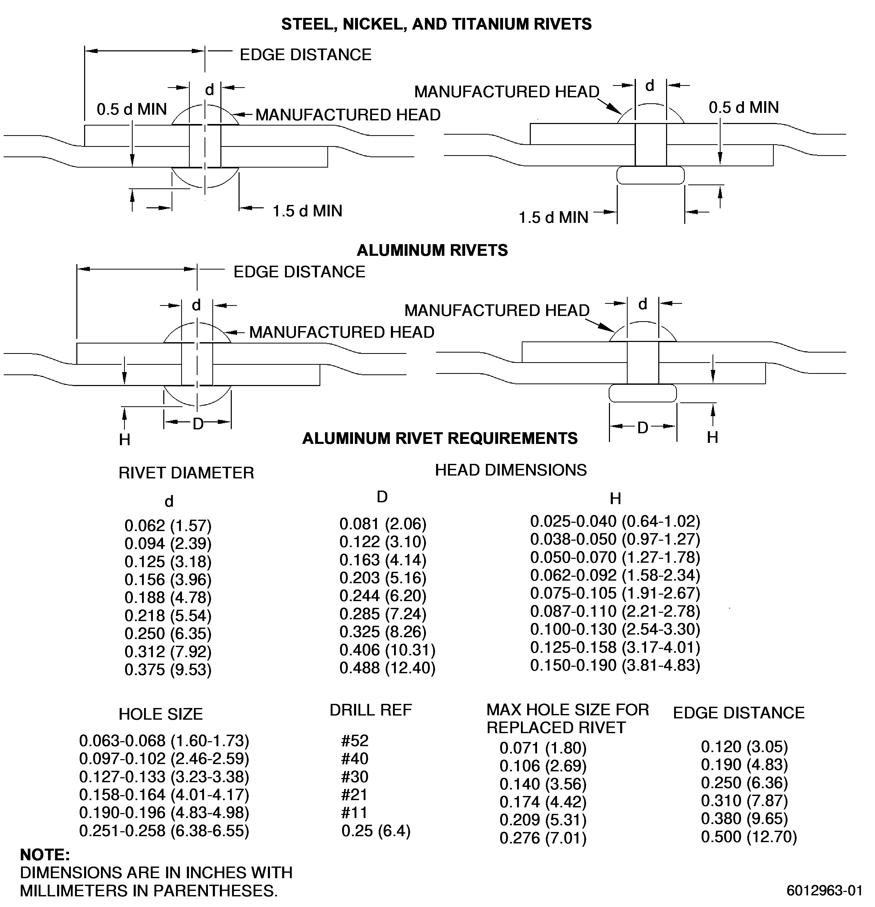
| A. | Dimensions of driven heads shall conform to the requirements illustrated in Figure 2. |
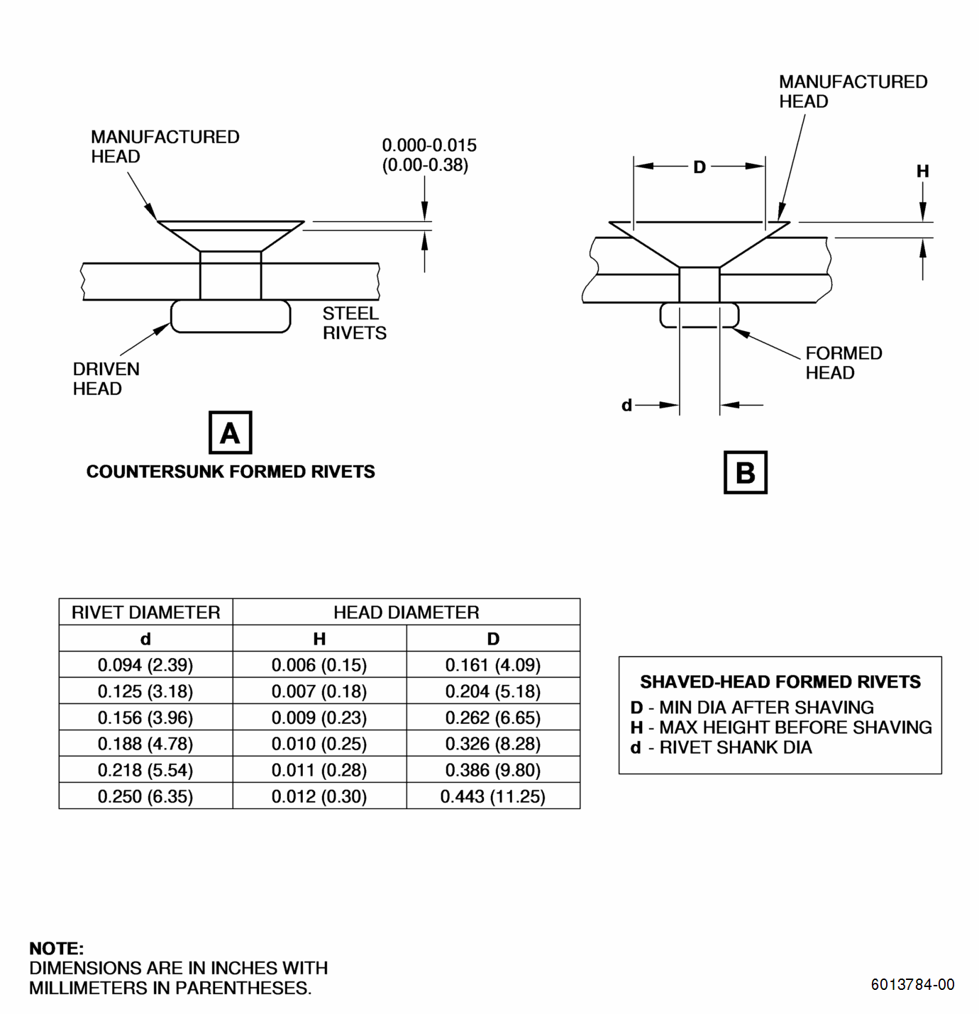
| B. | Countersunk steel rivets (flush-head) should fill the countersink or dimpled hole so that the manufactured head is flush to 0.015 inch (0.38 mm) below the surrounding surface. When flush riveting is required on both sides of the work, both heads should be flush to 0.015 inch (0.38 mm) below the surface. See Detail A, Figure 1. Riveting is to be accomplished with a mandrel on the manufactured head side equal to or slightly smaller than the head diameter. |
| C. | When shaving of countersunk head is required, the head shall not extend above the surrounding surface more than the distance shown in Figure 1. After shaving, the rivet head shall be flush with the surface. |
| 4 . | Length. |
| Subtask 70-13-01-390-023 |
| A. | When the length of a steel rivet is specified in repair or other instruction, the length may vary by one increment, depending upon whether the parts to be joined are on the high side or the low side of the tolerance. In any case, the rivet must be long enough to form the driven head to minimum requirements. (General Rule:1.5 x diameter protruding through work piece for steel rivets.) |
| NOTE: |
|
| 5 . | Material Defects. |
| Subtask 70-13-01-390-024 |
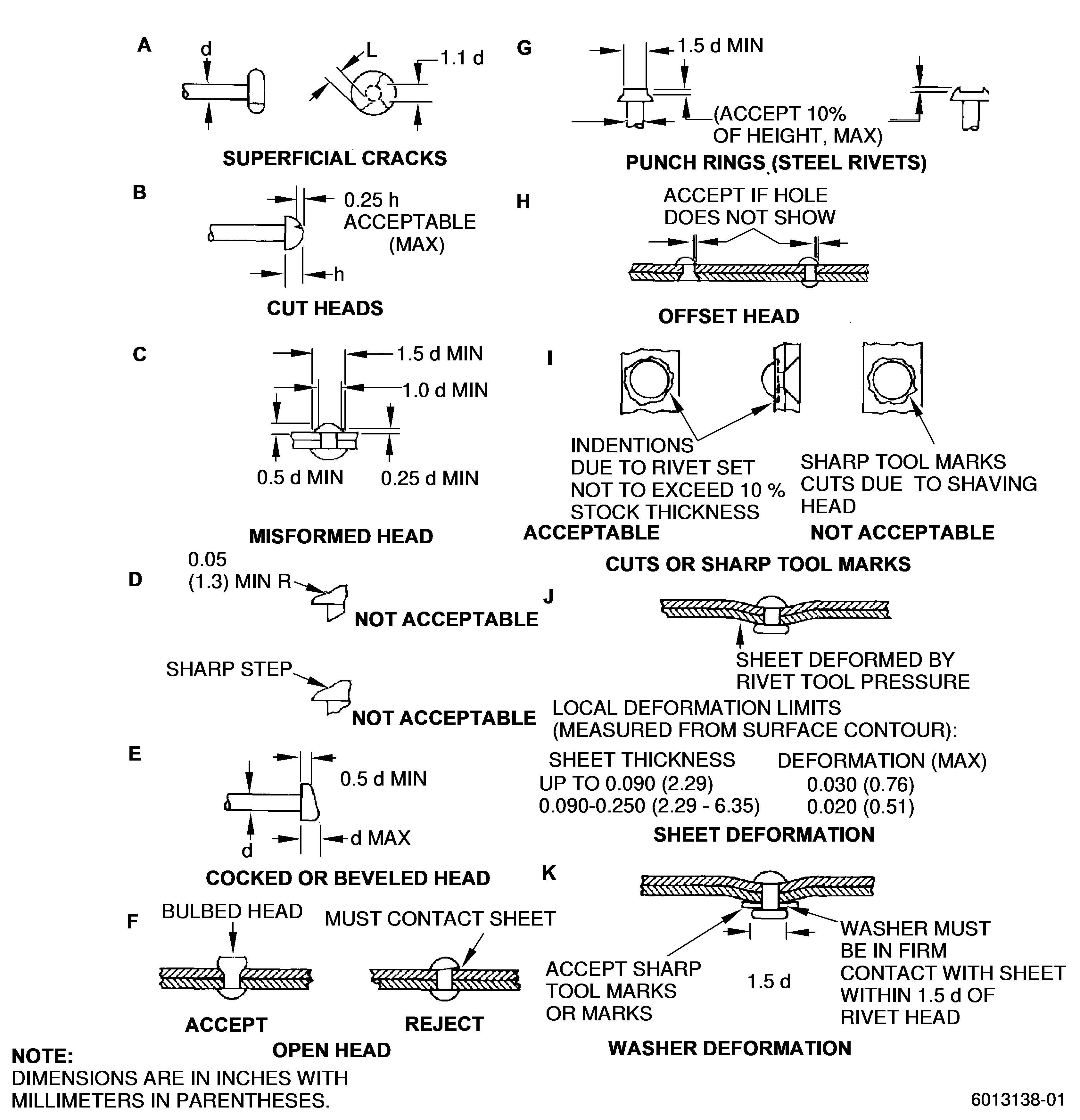
| A. | See Figure 3. Rivets with open breaks or splits in either head are not acceptable. Superficial heading splits or hairline cracks that cannot be felt with a 0.030 inch (0.76 mm) scriber are acceptable if they do not extend into a circle 1.1 times the shank diameter concentric with the shank(see A, Figure 3), and conform to the following requirements. |
| (1) | The cracks shall be approximately radial. |
| (2) | Cracks shall not intersect each other. |
| (3) | There shall be no more than 4 cracks per rivet head. |
| (4) | The length (L) of cracks, as shown in A, Figure 3, shall be within the limits shown in the following table. |
| B. | Cut heads are acceptable if the maximum depth of the cut is not more than one-quarter of the normal height of the head. (See Detail B, Figure 3.) |
| C. | Rivets that have misformed heads are acceptable provided: |
| (1) | Heads meet the minimum requirements as given in Detail C, Figure 3. |
| (2) | Contour of step is not sharp (see Detail D, Figure 3). |
| D. | Cocked or beveled heads are acceptable if the head is within the limits shown in Detail E, Figure 3. |
| E. | Bulbed heads are acceptable, but heads that do not contact the stock on all sides shall be rejected. (See Detail F, Figure 3.) |
| F. | Punch rings made with automatic riveting machines which are above or below the surface flat are acceptable within limits specified in Detail G, Figure 3. |
| G. | Offset heads are acceptable if the edge of the hole is not visible at any point (see Detail H, Figure 3). |
| H. | Cuts or sharp tool marks around a rivet head due to excessive pressure of rivet gun or tooling. See Detail I, Figure 3 for limits. |
| I. | Deformation of sheet due to pressure on the rivet is acceptable within the limits shown in Detail J, Figure 3. |
| J. | If a washer is used under the driven head, it shall be in firm contact with the sheet and within the limits shown in Detail K, Figure 3. |
| K. | Superficial pitting, stretch marks, folds, stringers(material defect) and slag inclusions are acceptable. Stringers and inclusions shall be no longer than twice the length shown in the table in paragraph 5.A.(4). |
| L. | Hanging chips or flakes at the edge of the driven head, and feathered edges that result in loose material at the extremity of the head are not acceptable. |
| M. | Indications on the manufactured head that are not interpreted as cracks are acceptable if they are up to 0.005 inch (0.13 mm) deep. |
| 6 . | Oversized Rivets. |
| Subtask 70-13-01-390-025 |
| A. | Rivets from 0.062 (1.58 mm) through 0.156 (3.96 mm) may be replaced with rivets 0.015 (0.38 mm) oversize or 0.032(0.81 mm) larger for repair or rework. Do not use oversize rivets in more than 5 adjacent holes. Hole size and edge distance must conform to the requirements of Figure 2. |
| 7 . | Countersunk Holes. |
| Subtask 70-13-01-390-026 |
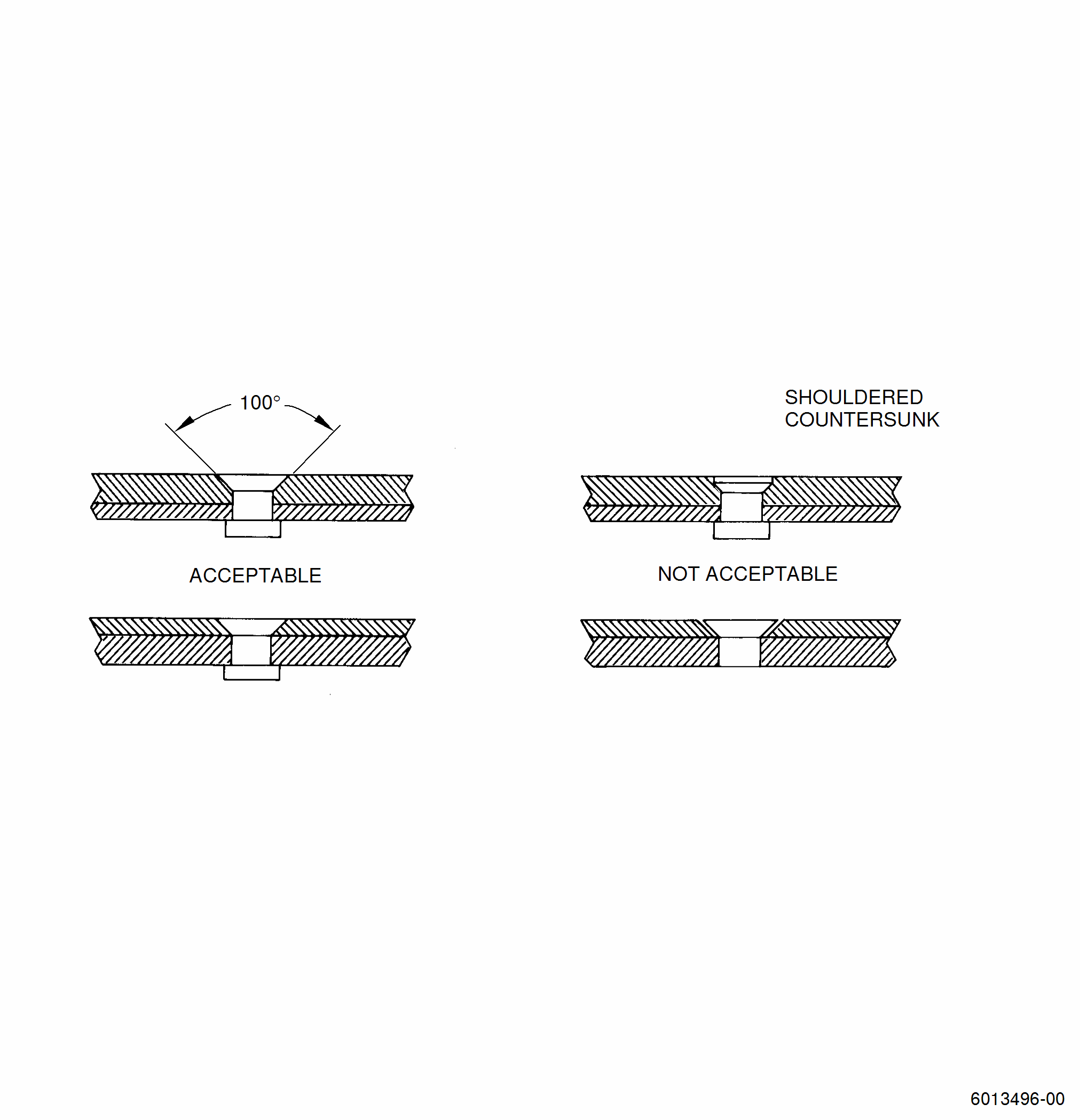
| A. | Countersunk holes shall have a nominal included angle of 100 degree and be of sufficient diameter to meet applicable flushness requirements. A shoulder countersink to accommodate the land on a fastener is not acceptable. In nonstructural applications where the countersink extends through more than one sheet, a countersink deep enough to provide a proper bearing for the fastener shall be produced as shown in Figure 7. |
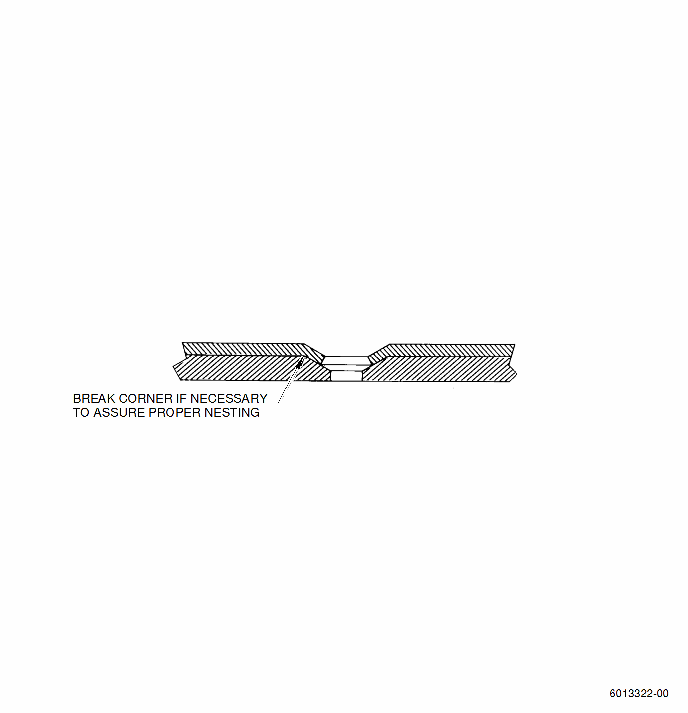
| B. | Subcountersinking is used for mating a coin-dimpled surface sheet with its corresponding substructure. The nominal countersunk angle shall be 100 degrees. The diameter shall be large enough to ensure a fit with the underside of the dimple. When a subcountersink is used with a conventional or large radius dimple, the top edge of the countersink shall be chamfered to provide clearance for a proper fit. |
| (1) | When a countersink is used with a conventional dimpled surface, the edge of the countersink cone shall be chamfered to provide a clearance for proper nesting. See Figure 6. |
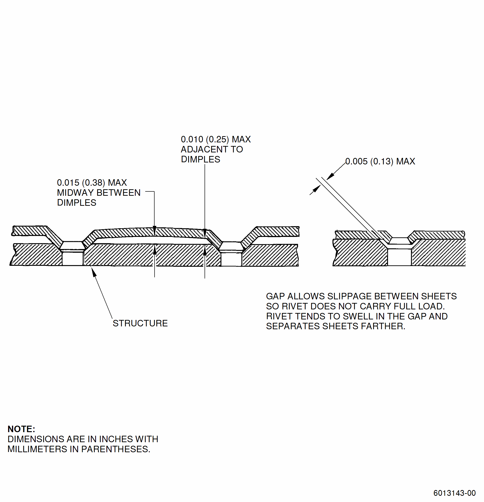
| (2) | Gaps between dimpled sheets and a countersunk sheet shall not exceed the limits shown in Figure 5. |
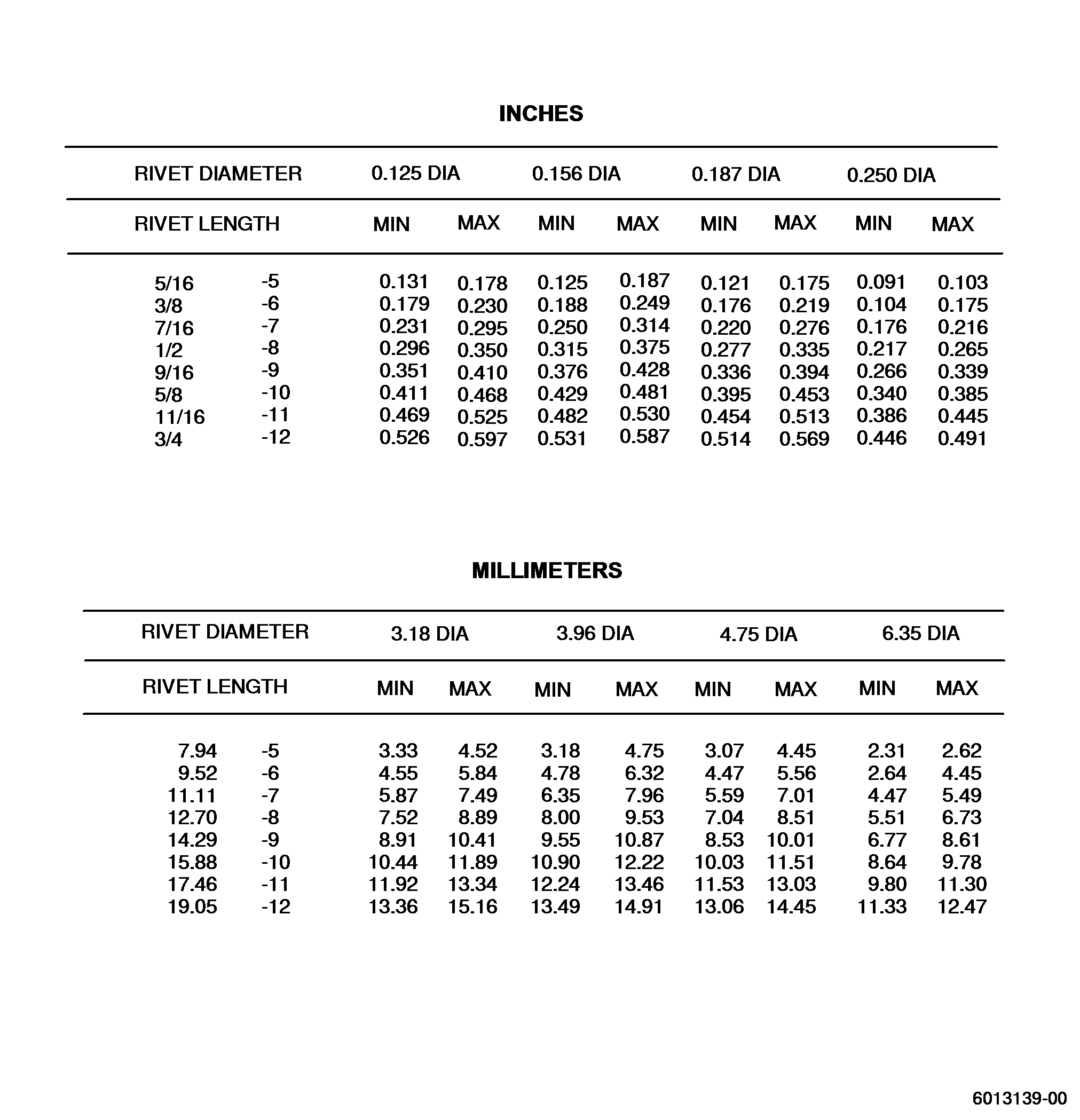
| C. | Figure 4 presents data on recommended rivet length selection for aluminum rivets, only. |