| COMMERCIAL ENGINE STANDARD PRACTICES MANUAL | Dated: 10/01/2006 | |
| SPM 70-16-08 DOT PEEN MARKING FOR OPTICAL CHARACTER RECOGNITION | ||
| COMMERCIAL ENGINE STANDARD PRACTICES MANUAL | Dated: 10/01/2006 | |
| SPM 70-16-08 DOT PEEN MARKING FOR OPTICAL CHARACTER RECOGNITION | ||
| TASK 70-16-08-350-001 |
| 1 . | General. |
| A. | Dot peen marking is a permanent marking process where characters are formed by a series of indentations or dots. The spacing between dots and characters are controlled by a microprocessor. This is a sub-set of metal stamp identification but under a carefully controlled process. |
| B. | The identification string which is required for dot peening will be indicated in the repair procedure. |
| C. | Location for identification should also be specified in the repair procedure. |
| 2 . | Equipment. |
| Subtask 70-16-08-350-001 |
| A. | PyroMark V 2068 (or equivalent), manufactured by Dapra Corporation. Refer to the List of Suppliers in Step 4 of 70-80-00. |
| B. | Technifor CN210Sm with Electromagnetic Stylus (table mounted or portable model) (or equivalent), manufactured by Technifor SA. Refer to the List of Suppliers in Step 4 of 70-80-00. |
| C. | Telesis TMP4100/420 or TMP1700/420 (or equivalent), manufactured by Telesis Technologies, Inc. Refer to the List of Suppliers in Step 4 of 70-80-00. |
| 3 . | Materials. |
| Subtask 70-16-08-350-002 |
| A. | Scotch Pad C10-010 . |
| 4 . | Reference Publications. |
| Subtask 70-16-08-350-003 |
| A. | 70-16-00, Marking Practices |
| B. | AS 478, Identification Marking Methods |
| C. | ANSI x 3.93M, Character positioning for optical character recognition (OCR) |
| D. | ANSI x 3.17, Character set for optical recognition (OCR-A) |
| 5 . | Definitions. |
| Subtask 70-16-08-350-004 |
| A. | Font - A style of alphanumeric and symbolic characters with unique type and face (for example, Gothic, Roman, OCR-A, 5 x 7 Dot Matrix). |
| B. | Optical Character Recognition (OCR) - An automatic data-entry system that utilizes predefined human-readable shaped alphanumeric character fonts which can be read by automatic scanning equipment. |
| C. | 5 x 7 Dot Matrix Marking - An alphanumeric and symbol character set where each character is formed by a series of individual dots arranged on a 5 x 7 (width x height) matrix. The dots are concave shaped depressions formed in the marked surface by a tool. |
| D. | OCR-A - A specific set of alphanumeric characters and symbols containing 96 graphic shapes and the character space, for use in OCR systems. |
| 6 . | Requirements. |
| Subtask 70-16-08-350-005 |
| A. | Dot-Peen marking must be defined by the parameters specified in Table 1, 2, and 3. Specific requirements will be listed in the appropriate part repair document. |
| B. | Dot-Peening Requirements. When Dot-Peening marking is used on parts that have the Life Limits specified in the Time Limits section of the Engine/Shop Manual the following requirements shall apply: |
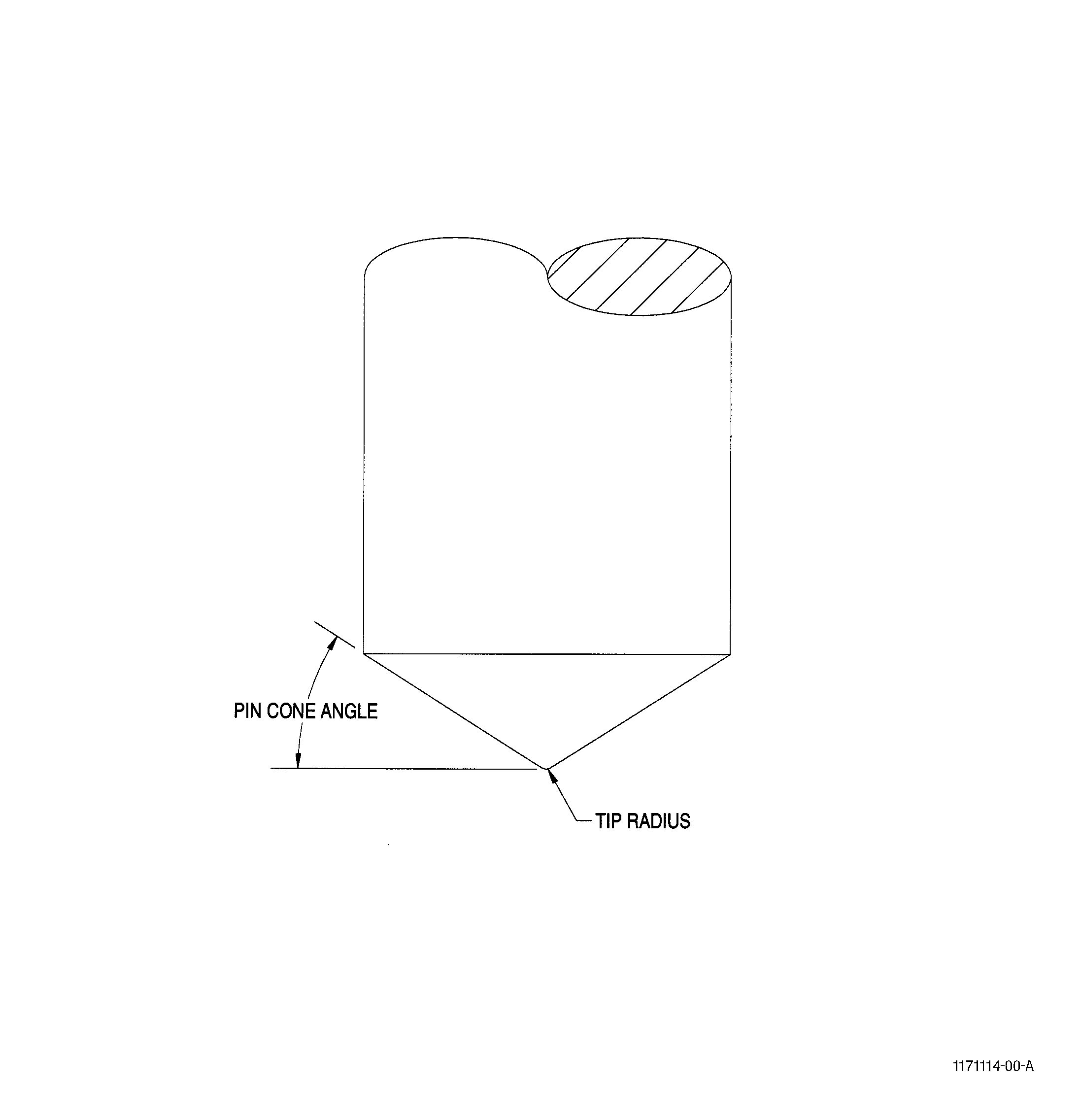
| (1) | The marking pin's cone angle( Figure 3) shall be 32 degrees maximum. |
| (2) | The marking pin's tip radius( Figure 3) shall be 0.010 inch (0.25 mm) minimum. |
|
||||||||||||||||||||||||||||||||||||||||||||||||||||||||||||||||||||||||||||||||||||||||||||||||||||||||||||||||||||||||||||||||||||||||||||||||||||||||||||||||||||||||||||||||||||||||||||||||||||||||||||||||||||||
|
||||||||||||||||||||||||||||||||||||||||||||||||||||||||||||||||||||||||||||||||||||||||||||||||||||||||||||||||||||||||||||||||||||||||||||||||||||||||||||||||||||||||||||||||||||||||||||||||||||||||||||||||||||||||||||||||||||||||||
| (3) | The pin stroke (the distance the pin travels prior to contacting the part being marked) and pressure shall be adjusted to obtain proper marking depth. |
| (4) | Method 2 shall be used unless otherwise specified in the repair document. |
| C. | Legibility. Characters shall be legible without magnification. |
| (1) | Type of Lettering. |
| (a) | The marking shall be block-form capital letters and Arabic numerals without serifs (for example, Gothic or Futura). |
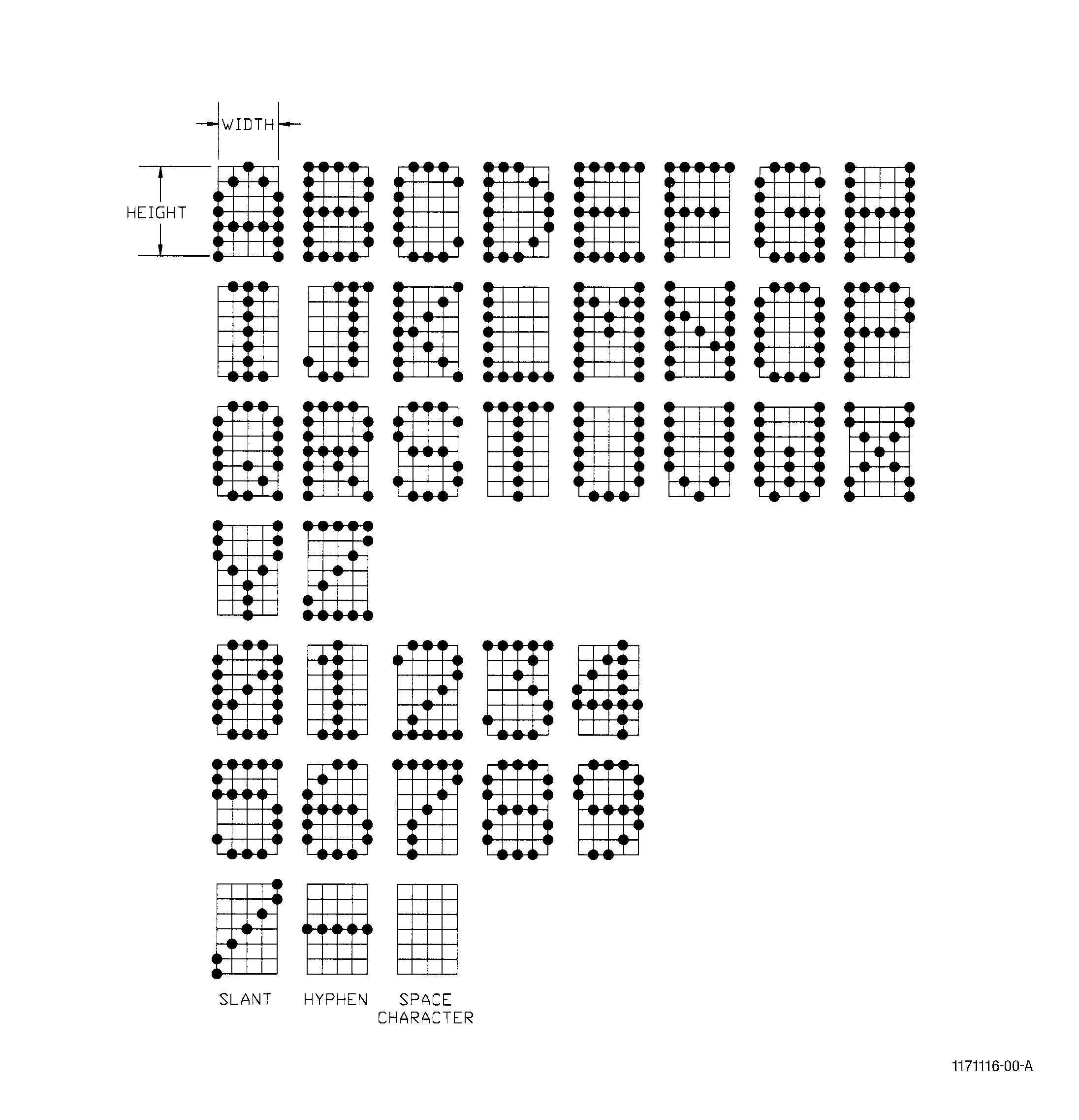
| (b) | When manual marking methods are used (that is, when the tool is guided by hand in contrast to being mechanically guided) the form of numeric characters shall be as shown in Figure 2. |
| (c) | The number 1 must be made exactly as shown in Figure 2, not just a straight vertical line. |
| (d) | The number 0 must have a slanted line through it as shown in Figure 2, not just an open circle. |
| (e) | The number 7 must be as shown in Figure 2, without a horizontal bar. |
| (2) | Depth |
| (a) | Depth will vary with the alloy being marked. Qualification tests must be performed for each alloy type and marking depth combination. |
| (b) | Depth will be specified in the repair and may vary from shallow 0.002 to 0.006 inch (0.015 to 0.15 mm) deep as shown in Table 1. |
| (3) | Character size |
| (a) | Optical Character Recognition (OCR). When optically recognized character marking is required, the designator OCR and the applicable OCR font designator shall be specified in the repair document following the marking method number. For example, if the Engine/Shop Manual specifies: |
| MARK PER METHOD X OCR-DM3 |
| The X specifies the Marking Method Number (see the left column in Table 1) |
| The OCR specifies that OCR characters must be used. |
| The DM-3 specifies the Font Designator (see the left column in Tables 2 and 3). |
| (b) | 5 x 7 Dot Matrix Marking. The 5 x 7 matrix is a set of points defined by the intersection of seven horizontal (height) and five vertical (width) lines, all of which are equally spaced. The center of the individual dots shall be marked at the designated intersection on the matrix( Figure 2). The marking character's height, width, spacing requirements and positional controls are specified in Table 2. |
| 1 | The height of each character can vary from 0.048-0.150 inch (1.21-3.81 mm). Measure from the center of the characters highest and lowest positioned dots for all characters but the hyphen and space characters. |
| 2 | The width of each character can vary from 0.048-0.100 inch (0.36-2.54 mm). Measure from the center of the character's furthermost left and right positioned dots for all characters but the number one and space characters. |
| 3 | The character spacing can vary from 0.076-0.150 inch (1.94-3.81 mm). This is the horizontal distance between two adjacent character's vertical center lines. |
| 4 | Character skew is less than 3.0 degrees. |
| 5 | The maximum deviation from the average base line can vary from 0.008-0.025 inch (0.20-0.64 mm). |
| 6 | The minimum line separation can vary from 0.025-0.075 inch (0.60-1.91 mm). |
| (c) | OCR-A Marking. Requirements for the standard OCR-A character set are specified in ANSI x 3.17. The OCR-A marking character's height, width, spacing and positional requirements are specified in table 3. |
| 1 | The height of each character can vary from 0.030 (0.76 mm) to 0.083 inch (2.11 mm). Character height measurements are referenced from the center of the character's scribe line. |
| 2 | The width of each character can vary from 0.015 inch (0.38 mm) to 0.042 inch (1.07 mm). Character height measurements are referenced from the center of the character's scribe line. |
| 3 | The character spacing can vary from 0.025 inch (0.63 mm) to 0.068 inch (1.73 mm). This is the horizontal distance between two adjacent character's vertical center lines. |
| 4 | Character skew is less than 3.0 degrees. |
| 5 | The maximum deviation from the average baseline can vary from 0.005 inch (0.13 mm) to 0.014 inch (0.36 mm). |
| 6 | The minimum line separation can vary from 0.015 inch (0.38 mm) to 0.042 inch (1.07 mm). |
| D. | Marking Location. Unless specifically defined in the repair procedure, the specified marking shall be allowed anywhere on the surface indicated on the engineering part drawing within the following limitation. |
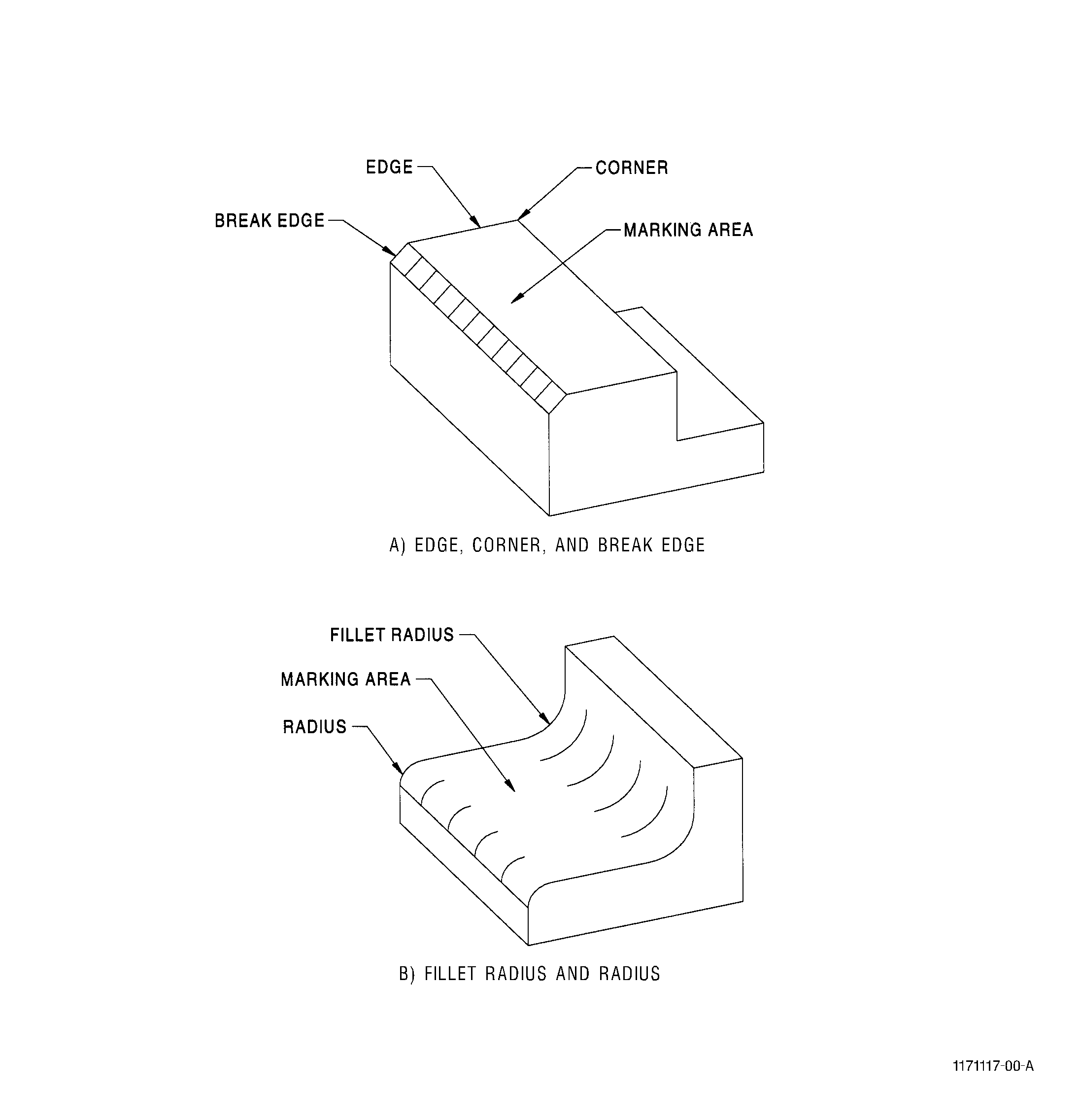
| (1) | Edge Clearance. Permanent markings shall not be nearer than 0.031 inch (0.78 mm) to any corner, fillet, radius, edge, or break-edge unless specifically designated. Where the designated marking location does not provide enough area for the 0.031 edge clearance, the markings shall be centered upon the area without breaking over a corner, edge, break-edge, or a tangent point of a fillet or radius( Figure 1). |
| (2) | Bolts, Studs, Screws, and Nuts. When identification marking is required on bolts, screws, studs, or nuts, the item shall be marked in accordance with this specification, but due to the limitations of available marking area, the following exceptions apply. |
| (a) | Unless otherwise specified in the repair document, the marking may be located on any non-wrenching or non-bearing surface, except that bolts, screws, or studs shall not be marked on the reduced shank area. Reference paragraph 6.D. (marking location). |
| (b) | Edge distance requirements of paragraph 6.D.(1) do apply. The term edge as applied to hexagon head bolts is defined as the intersection of the hexagon flats with the top of the head; on double hexagon head bolts the edge is the intersection of the root of two adjacent flats with the top of the head. |
| (c) | The marked character sizes shall be in accordance with AS 478. |
| E. | Arrangement. The arrangement for identification and traceability mark shall be in accordance with the Engine/Shop Manual. If instructions are not specified, follow TASK 70-16-00-350-001, Marking Practices, for permanent marking. |
| 7 . | Procedure. |
| Subtask 70-16-08-350-006 |
| A. | Prepare the system by programming the appropriate identification string in the unit. |
| B. | Make sure that the part is clean and free from all grease, oil, or film prior to marking. Lightly burnish the area to be marked with the Scotch Brite Pad C10-010 . |
| C. | Carefully remove all projections produced on the surface by the displaced metal. |
| 8 . | Quality Requirements. |
| Subtask 70-16-08-350-007 |
| A. | Process qualification for depth of marking should involve metallographic cross sections to determine stamp penetration. |
| B. | The samples used for qualification must meet the parameters below to be representative of actual part processing: |
| Same Alloy |
| Same heat treat condition |
| Same surface treatment (if applicable) |
| Same surface finish |
| Minimum 0.030 inch (0.76 mm) thickness |
| C. | Qualification will be required for each alloy/depth combination used during part marking. |
| D. | Maintain the tip radius as calibrated tooling under calibration control. See Step 6.B.(2) in Subtask 70-16-08-350-005, Requirements. |