| COMMERCIAL ENGINE STANDARD PRACTICES MANUAL | Dated: 01/05/2024 | |
| SPM 70-23-23 REMOVAL OF COATINGS BY HIGH PRESSURE WATER STRIPPING | ||
| COMMERCIAL ENGINE STANDARD PRACTICES MANUAL | Dated: 01/05/2024 | |
| SPM 70-23-23 REMOVAL OF COATINGS BY HIGH PRESSURE WATER STRIPPING | ||
| TASK 70-23-23-330-008 |
| 1 . | General. |
| A. | This stripping method uses jets of high pressure water directed by small rotating nozzles to remove coatings. The procedure must have a high degree of control and repeatability. |
| B. | The equipment for this procedure must supply water to the stripping jets at a very high pressure. |
| C. | The materials (stripping coupons and sample piece part for evaluation) are to be provided by the source seeking approval. |
| 2 . | Equipment. |
| Subtask 70-23-23-330-081 |
| A. | The equipment used to do the high pressure water stripping procedure is as follows: |
| (1) | Permit the stripping head to be positioned as necessary to remove the coating. Generally standoff distances of 0.5 inch (13 mm) to 3.0 inches (76 mm) are recommended. |
| (2) | Permit the nozzles to be set up in the same position for each operation. Stripping is recommended with a nozzle to work piece angle between 80 and 100 degrees. |
| (3) | Keep the part and/or the stripping head moving to prevent erosion of the part surface, i.e. maintain relative motion between work piece and water jet nozzle. Static stripping (the part and stripping head do not move) is not permitted. |
| (4) | Have an interlock feature which prevents operation of the water jets until the part or the stripping head is in motion. The interlock should deactivate the water jets and the pump in the event the parameters fall outside the acceptable motion parameters limit. The control system used will prevent part damage from the water jets by accurately monitoring and controlling parameters. The system used, either articulated arm or robot should have a collision sensor which automatically activates an emergency stop. |
| (5) | Have pressures and flows that will remove the coating with minimum effect from the surface of the part. Water pressure is recommended to be between 20,000 and 60,000 psi (138,000-410,000 kPa). Water flows are typically from 0-4 gallons (0-15 liters) per minute. |
| (6) | Single or multiple orifice stripping heads can be used to remove coatings with minimal base metal removal. No requirements on the orifice size and/or number of orifices is defined. |
| (7) | Process parameters are dependent on the specific stripping head design chosen, depending on repair requirements. It is required to verify machine stripping parameters by stock loss and surface evaluations on sample coupons. Refer to Subtask 70-23-23-330-082, Process Requirements, for process demonstration requirements. |
| B. | Available vendors that have been identified as sources of complete systems are: |
| Progressive Surface. Refer to the List of Suppliers in Step 4 of 70-80-00. |
| Praxair / TAFA Concord. Refer to the List of Suppliers in Step 4 of 70-80-00. |
| Advanced Systems Technologies Incorporated (AST). Refer to the List of Suppliers in Step 4 of 70-80-00. |
| Flow International Corporation. Refer to the List of Suppliers in Step 4 of 70-80-00. |
| Aquarese Shape Technology Group. Refer to the List of Suppliers in Step 4 of 70-80-00. |
| CAUTION: |
|
| C. | The equipment parameters must be established prior to the use of the water jet stripping system for stripping of engine components. |
| D. | After machine parameters have been established, a scrap part should be stripped to verify machine stripping parameters and manipulator programming. |
| 3 . | Process Requirements. |
| Subtask 70-23-23-330-082 |
| A. | A demonstration of the procedure is necessary to achieve internal approval to strip hardware using the waterjet system. Unless special requirements are stated in the process document, the internal approval package should include the following data: |
| NOTE: |
|
| (1) | A description of the system and appropriate positioning and interlocking features. |
| (2) | Deleted. |
| NOTE: |
|
| NOTE: |
|
| (3) | Identification of the following parameters must be involved with the stripping procedure: |
| CAUTION: |
|
| (a) | Surface Feed/Footage per Minutes SFM (IPM) |
| (b) | Feed Rate (IPM) (inch/min) |
| (c) | Nozzle Rotation (rpm) |
| (d) | Turntable speed (relative surface speed) RPM (rev/min) |
| (e) | Stripping gun head/nozzle rotation (rpm) |
| (f) | Stripping head stand off distance (inch) |
| (g) | Traverse Speed (inch/rev) |
| (h) | Angle of attack to the part surface |
| (i) | Pressure (ksi or psi) |
| (j) | Number of nozzles and sizes |
| (k) | Total number of passes permitted in a repair shop visit based on stock loss and surface evaluation |
| (l) | Total number of passes required to remove the coating |
| NOTE: |
|
| NOTE: |
|
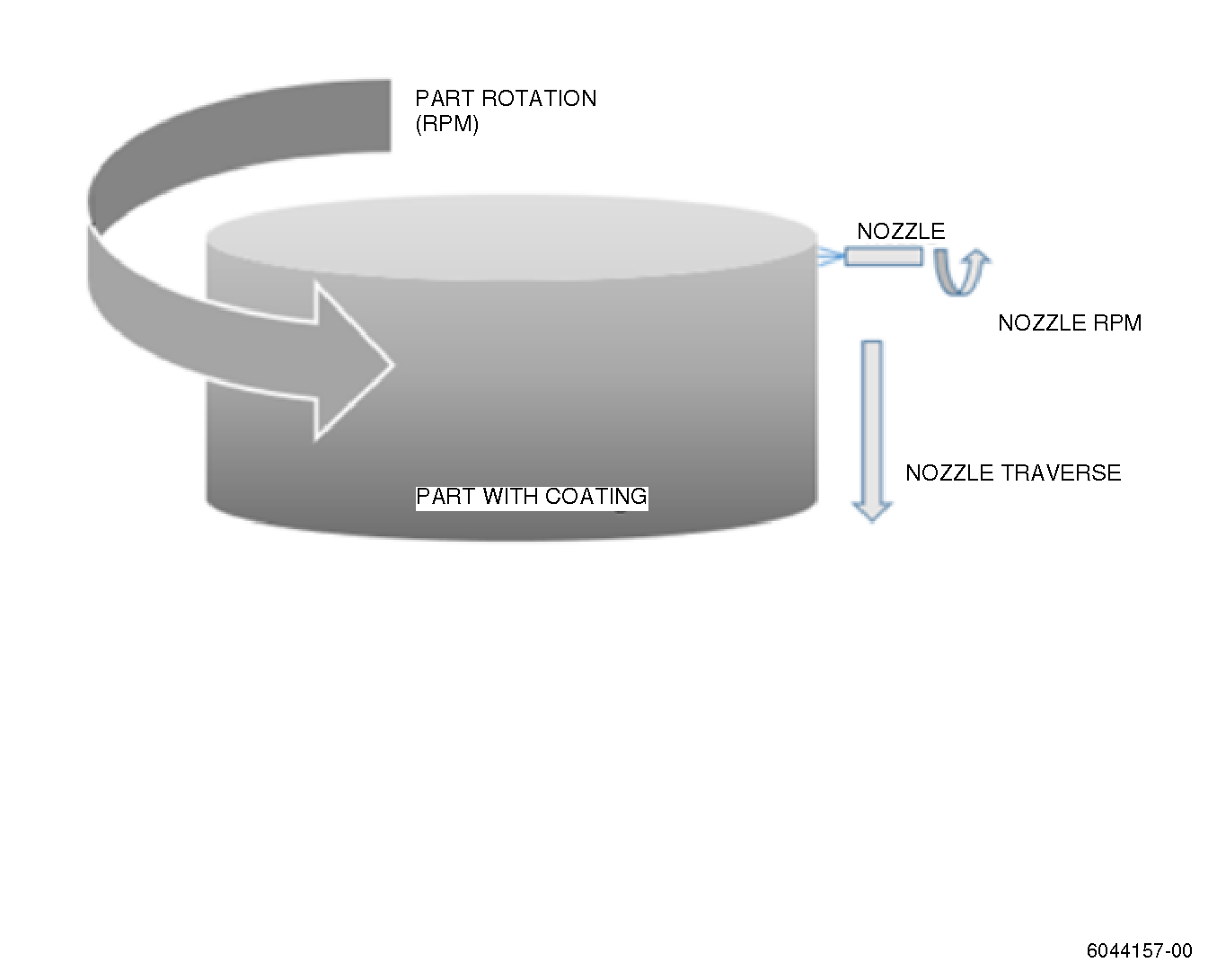
| (4) | Relation between system parameters. Refer to Figure 1 and as follows: |
| (a) | IPM (inch per min) or SFM = n * D * π. |
| (b) | Turntable RPM = IPM or SFM = π * D. |
| (c) | Feed Rate(IPM) = RPM (rev/min) * Strip Width (inch) * Percentage Overlap. |
| (d) | π = 3.141. |
| (e) | D = Part diameter. |
| (f) | n = Turntable speed (RPM)(rev/min). |
| (5) | Verify the machine stripping parameters. Do a demonstration on a sample uncoated coupon to verify the amount of base material removal/erosion and surface evaluations as follows: |
| (a) | Make a sample coupon from the same material as the part. |
| (b) | Set the machine to parameters to be approved by process qualification test. |
| (c) | Apply stripping parameters to verify the amount of base metal removal/erosion. |
| (d) | Visually inspect the processed area, visual evidence of pitting after high pressure water jet stripping is not permitted. Refer to Figure 2. |
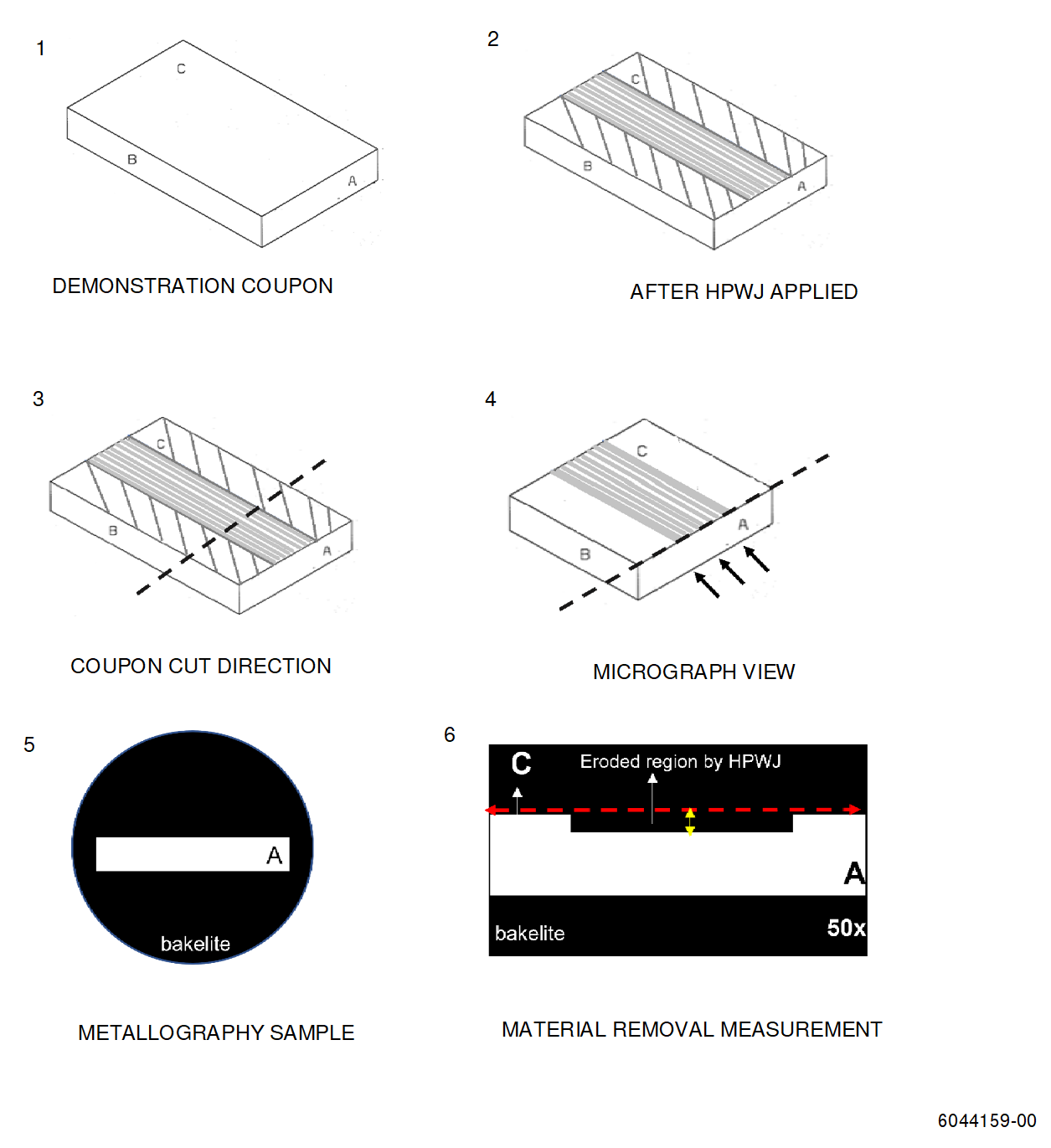
| (e) | Metallographically examine coupons with photo micrographs or by 3D measurement system that is able to scan the coupon area to find maximum material removal. Refer to Figure 3 to metallographic coupon preparation steps. |
| (f) | Check surface condition of processed surface with micrograph. The coupons used for material removal measurement can be used for surface evaluation. It is recommended to use an un-processed (reference) coupon to compare the surface texture in processed coupons. |
| (g) | Unless specified differently in engine manual, the maximum amount of base material removal permitted is 0.0010 inch (0.025 mm). This is the maximum number of passes permitted in a repair shop visit. Specify the maximum number of passes permitted in a shop visit based on stock loss and surface evaluation. |
| (h) | If more than 0.0010 inch (0.025 mm) was removed, adjust the equipment parameters, and repeat process qualification steps. |
| (6) | Perform a demonstration of the stripping process parameters on scrap/simulated part, which is the same base material, and has the same type of coating material with same coating thickness with part that will be stripped. Record the number of passes necessary for the coating removal. Number of passes required for coating removal must be within maximum number of passes permitted in a repair shop visit. |
| (7) | A demonstration on sample hardware. |
| 4 . | Procedure. |
| Subtask 70-23-23-330-083 |
| A. | Set up and fixture the part to be stripped in the water jet cell. The part must be fixtured to prevent excessive part movement during stripping and allow for precise nozzle to part orientation. |
| B. | Do the high pressure water jet stripping as follows: |
| (1) | Load appropriate CNC control program into the water jet cell controller for the type of part to be stripped. |
| (2) | Make sure the correct stripping head is attached to the machine as identified by the computer programmed instructions. Verify that each nozzle has the correct orifice size loaded. |
| (3) | Make sure the proper pressure is correctly set on the pump, if manual setting is necessary. |
| (4) | Start part rotation and/or stripping head moving. Both must achieve process parameter speeds before stripping starts(i.e., water on). |
| NOTE: |
|
| CAUTION: |
|
| (5) | Initiate the normally closed on/off valve to start waterflow to the nozzle or stripping head assembly. |
| (6) | Operate the equipment for the number of passes required to remove the coating or until the maximum number of passes allowed for the base metal has been achieved. The maximum number of passes is determined by the repair process evaluation or by specific criteria in the engine manual. |
| (7) | Deactivate the on/off valve to stop the water flow to the nozzle or stripping head assembly. |
| (8) | Stop the part and/or stripping head movement. |
| (9) | Record serial number of the stripped part in the work cell control log. |
| C. | Visually inspect the stripped surface of the part to verify the coating has been removed. Area's of residual coating after stripping prior to prep-for-thermal spray are allowed up to 5 percent as a percentage of the total coated surface area. |
| D. | Visual evidence of pitting after high pressure water jet stripping is not permitted. |
| E. | If some of the coating remains on the surface, remove as follows: |
| (1) | If the procedure plan permits, do the high pressure water strip procedure again. |
| (2) | If the procedure plan does not permit the high pressure water stripping procedure to be done again, remove the coating with a chemical stripping procedure. Refer to the Engine/Shop Manual that contains the part to be stripped or contact Product Support Engineering to get the correct chemical stripping procedure. |
| WARNING: |
|
| F. | Clean the part with compressed air or a water rinse and remove the part from the cell. |
| 5 . | Quality Assurance. |
| Subtask 70-23-23-330-084 |
| A. | Make sure that the water jet nozzles are not eroded. Monitor the process for its effectiveness at stripping or cleaning, and replace the nozzles as needed. For the nozzle life, refer to manufacturer recommendation if available. |
| B. | As part of the regular equipment maintenance schedule, do a check of the part movement/water pump safety interlock. |
| C. | Verify motion speed indications on the stripping nozzle or head assembly and part rotation tooling. |