| |
|
|
| |
|
| Clearance measured in a direction parallel to the engine centerline.
|
|
| |
|
| Movement of a part in a direction parallel to the engine centerline.
|
|
| |
|
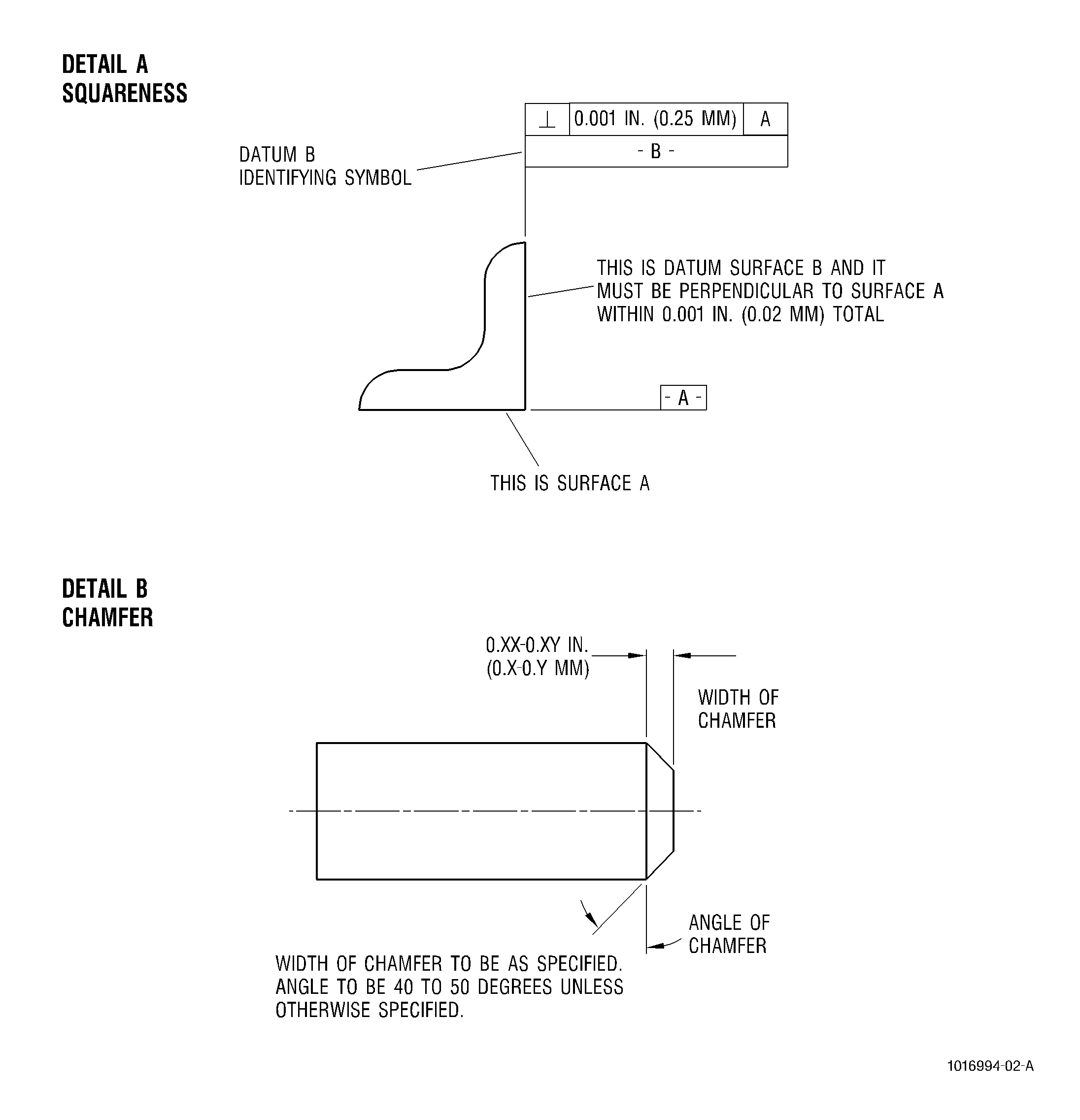
| The bevel machined or formed at an edge to eliminate a sharp corner.
|
|
| |
|
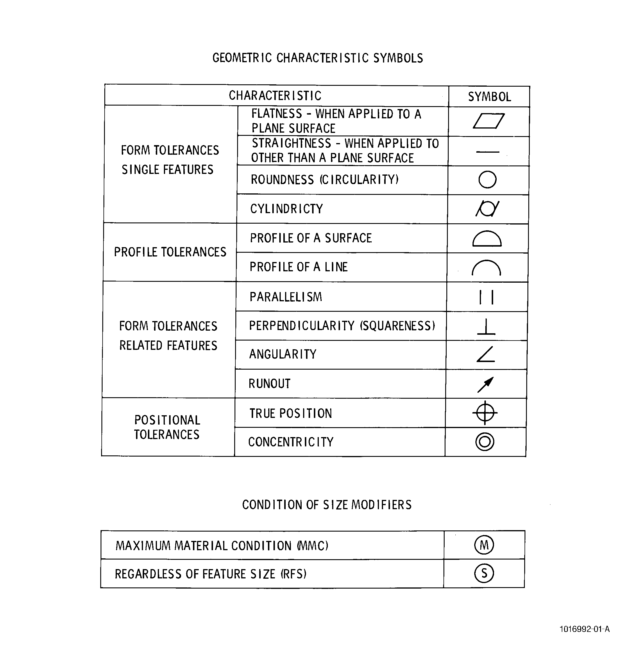
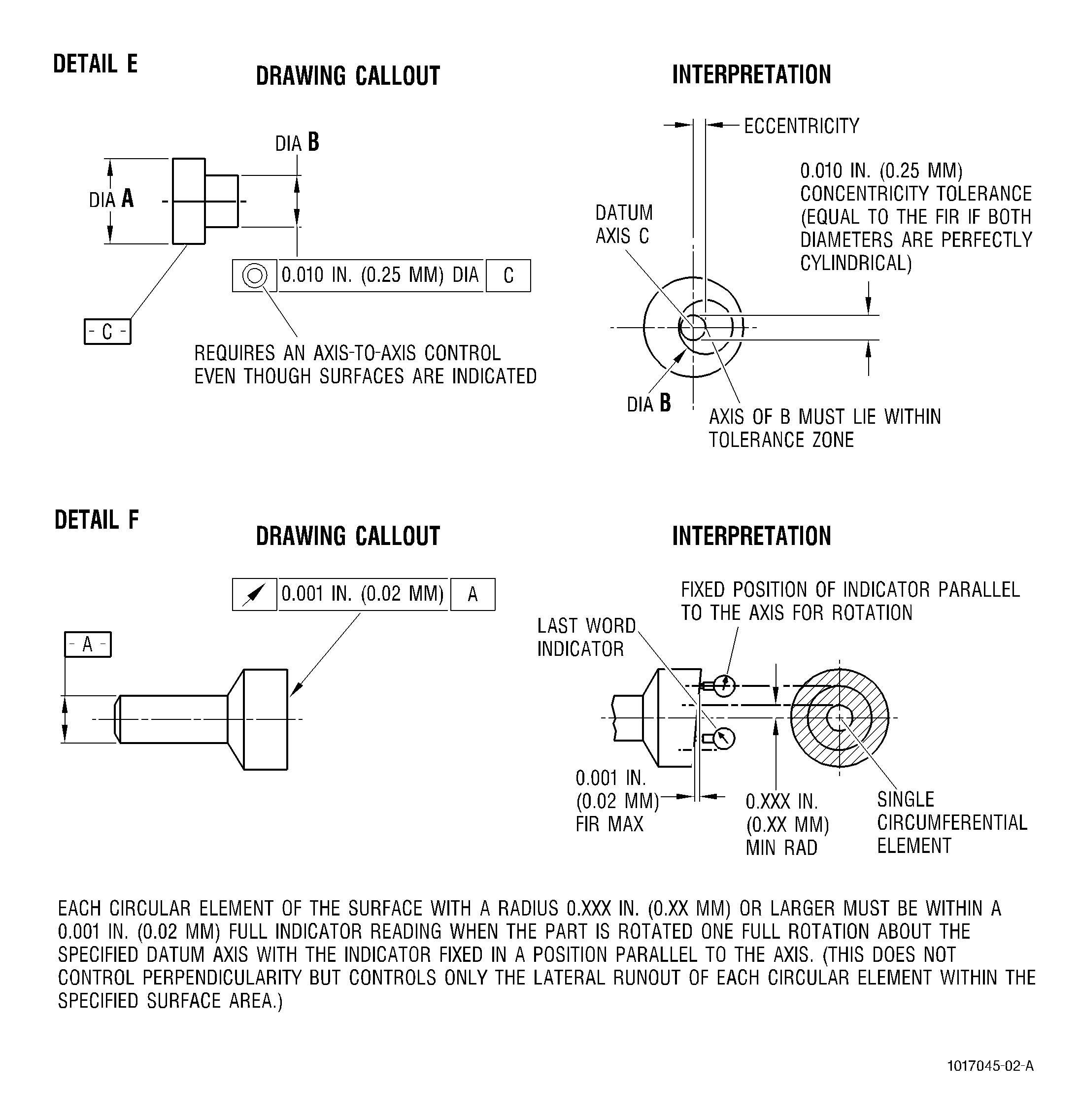
| The relationship between 2 circumferences having radii of different lengths, but the same center and direction.
|
| NOTE:
|
| Does not include total indentations or out-of-roundness. |
|
|
| |
|
| A line across a circle, which intersects and is perpendicular to the centerline.
|
|
| |
|
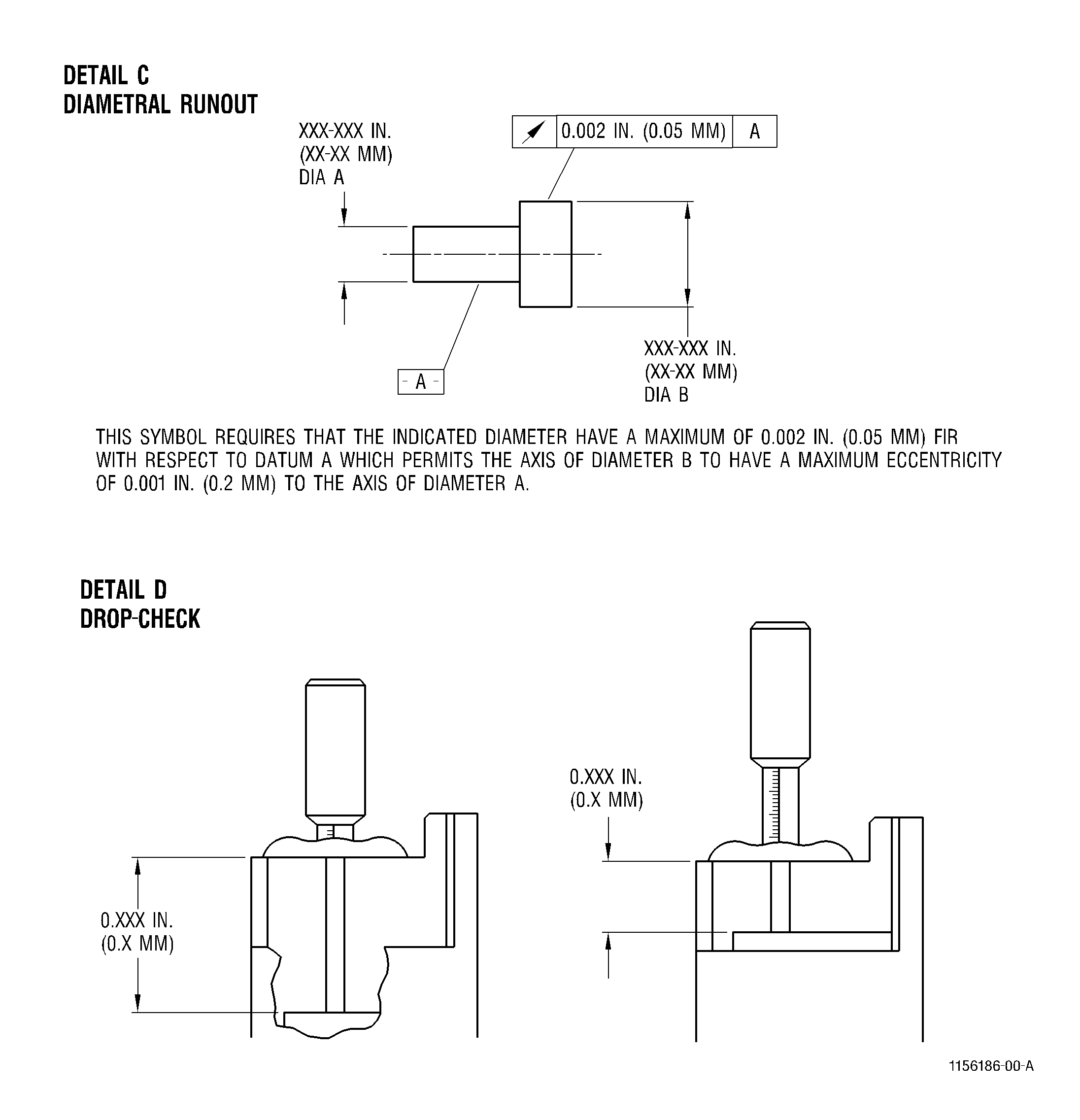
| The total indicator reading (TIR) shown when an indicator contacts a cylindrical or conical surface, and the piece is rotated 360 degrees about an established axis. The reading includes both the eccentricity and out-of-roundness.
|
|
| |
|
| The relative distance between 2 or more planes, measured from a common reference surface.
|
|
| |
|
| The distance between the axis of rotation and parallel axis through the geometric center of a part.
|
| NOTE:
|
| This condition does not include out-of-roundness or local imperfections. |
|
|
| |
|
| The total indicator reading shown when the indicator contacts the face of a workpiece at a fixed distance from an established axis, while the workpiece is rotated 360 degrees about that axis.
|
| NOTE:
|
| This method does not measure concavity or convexity, which are related to the term "flatness". |
|
|
| |
|
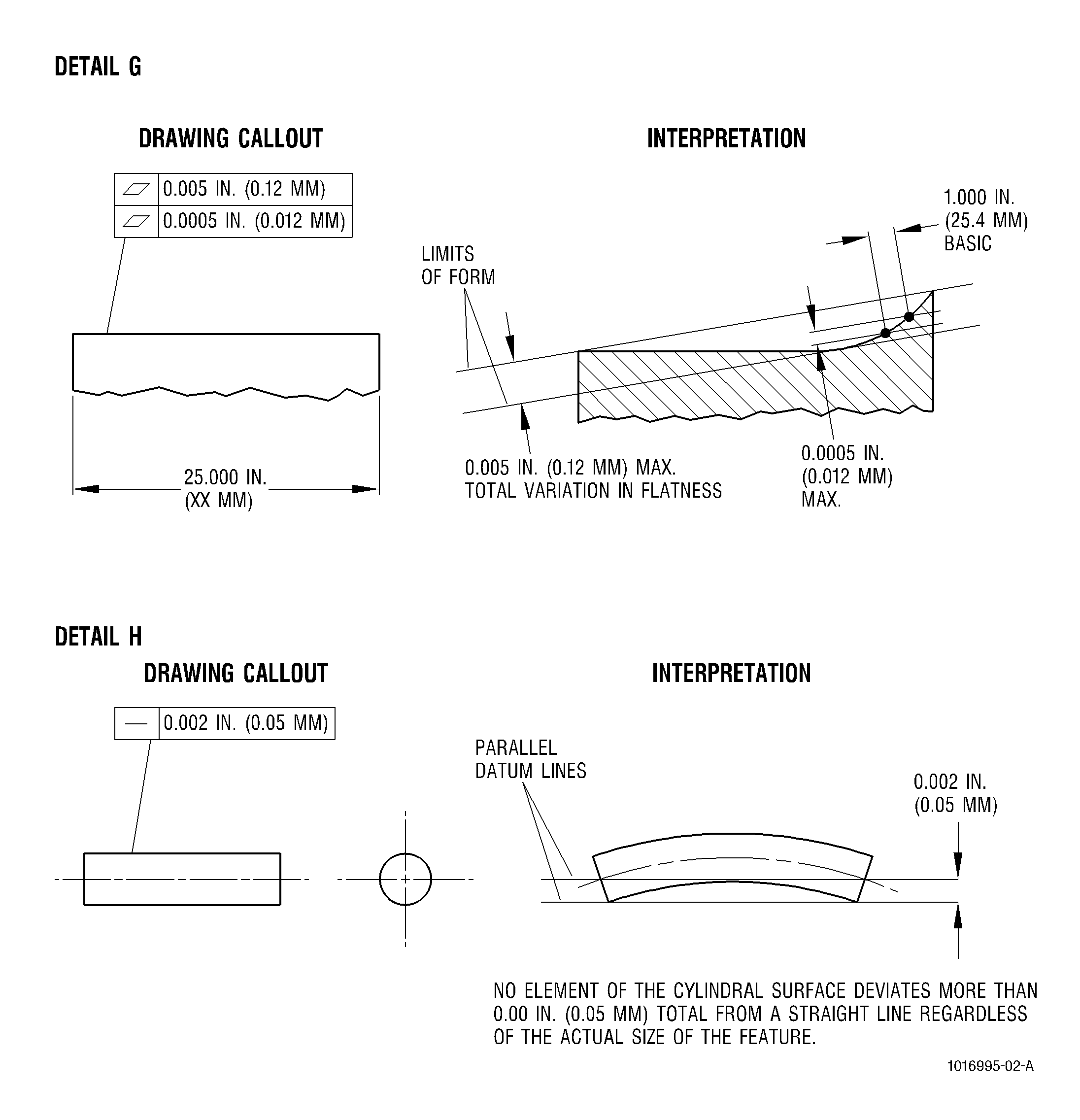
| The total deviation of a surface of a part from a true plane or straight edge.
|
|
| |
|
| Free from all external forces or constraints.
|
|
| |
| Full indicator reading (FIR)
|
|
| Refer to "total indicator reading" (TIR).
|
|
| |
|
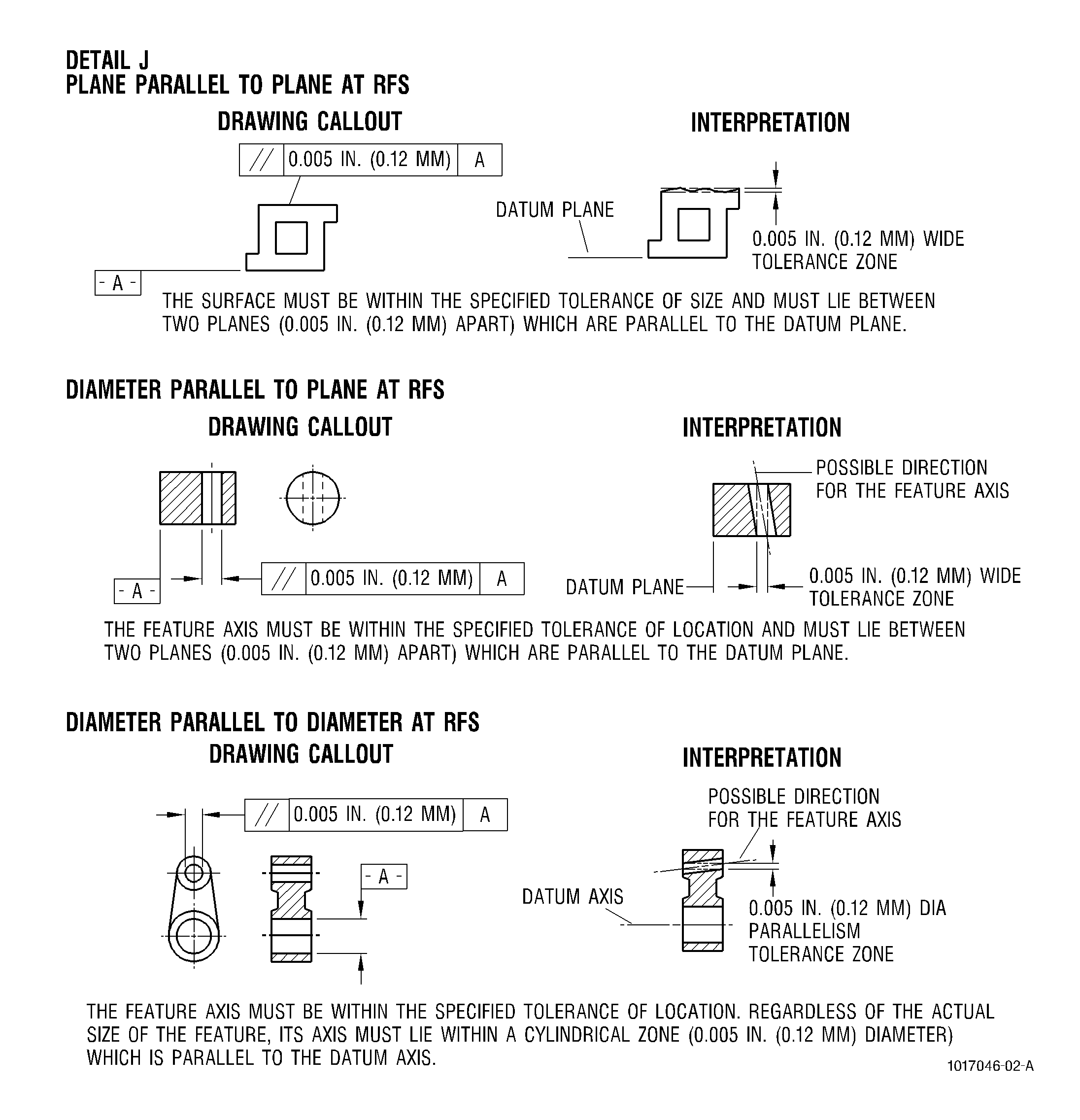
| Two or more straight lines or flat planes extending in the same direction, which are equidistant at all points.
|
|
| |
|
| Clearance measured in a direction perpendicular to the engine centerline.
|
|
| |
|
| The total indicator reading shown when an indicator is removed radially across the face of a part at 90 degrees to an established axis. This measurement will show any existing concavity/convexity.
|
|
| |
|
| Movement of a part in a direction perpendicular to the engine centerline.
|
|
| |
|
| The distance from the center to the circumference of a circle or arc.
|
|
| |
|
| The opposite of "free-state". The holding or clamping of a flexible part to a specified shape or configuration.
|
|
| |
|
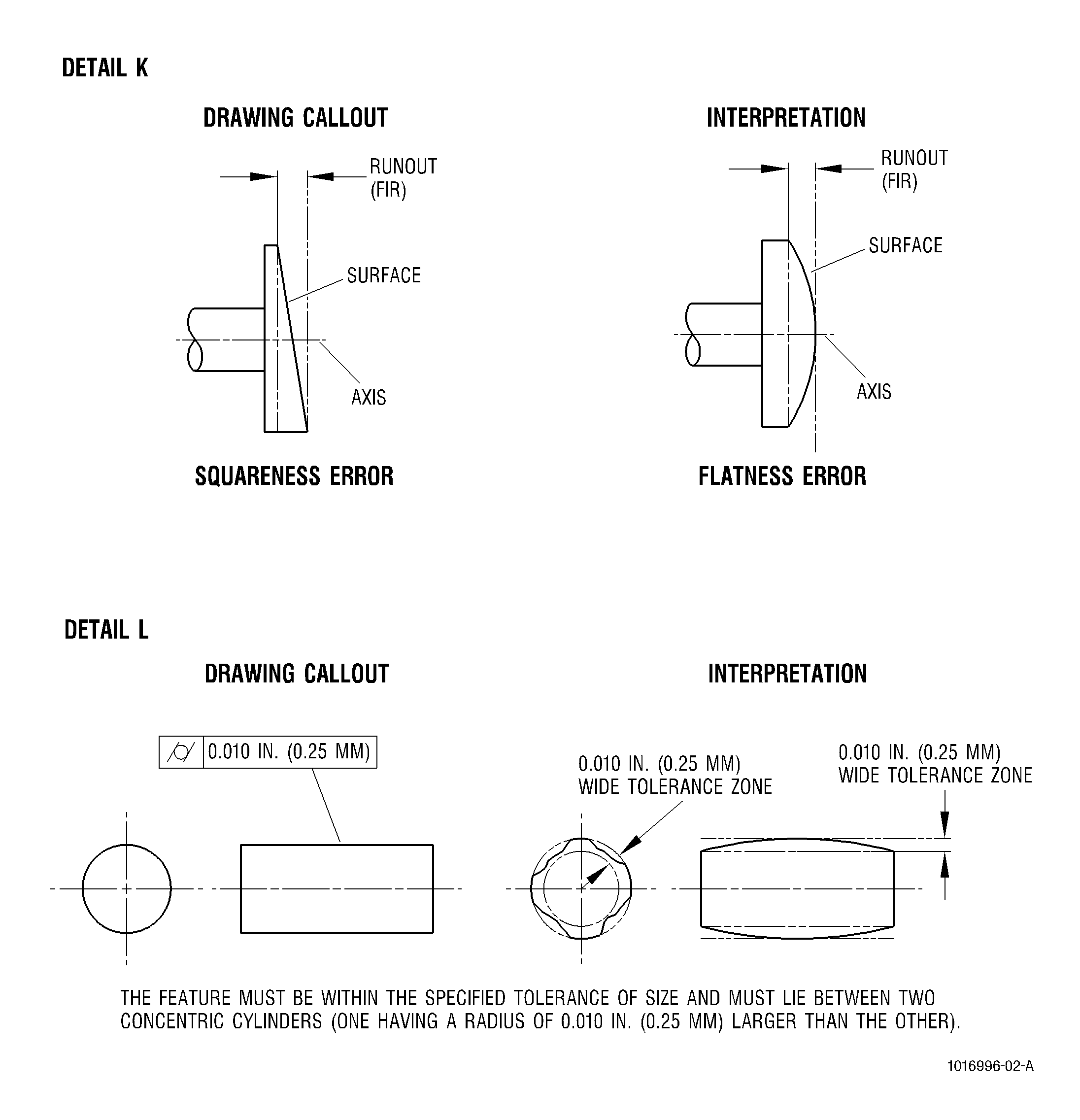
| Total radial variation from a true circle or cylinder; may be measured as the total indicator reading when the part is rotated 360 degrees about its own geometric center, or one-half the difference between the maximum and minimum diameters.
|
|
| |
|
| An outside corner formed by the intersection of 2 flat surfaces or by the intersection of a concave radius and another surface, which form an abrupt angle. Burrs may extend from the surface machined last, and thus increase the sharpness of the edge.
|
|
| |
|
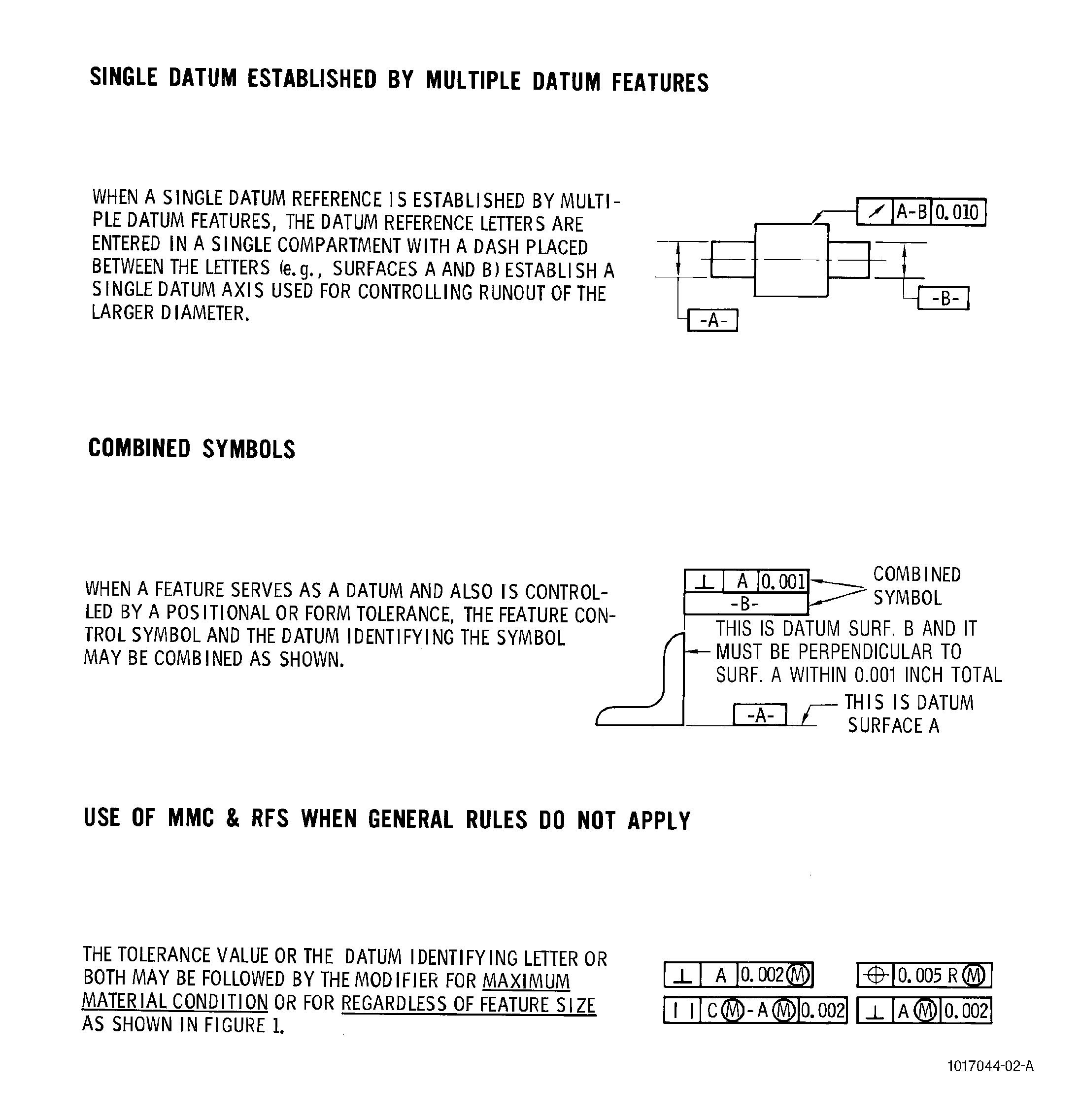
| The intersection of 2 lines, axes, planes or surfaces forming an angle of 90 degrees.
|
|
| |
|
| A tolerance zone of uniform width along a line that does not deviate in direction.
|
|
| |
|
| The mathematical difference between maximum and minimum readings of an indicator as it traverses one or more typical or specified lines on the surface being inspected.
|
|
| |
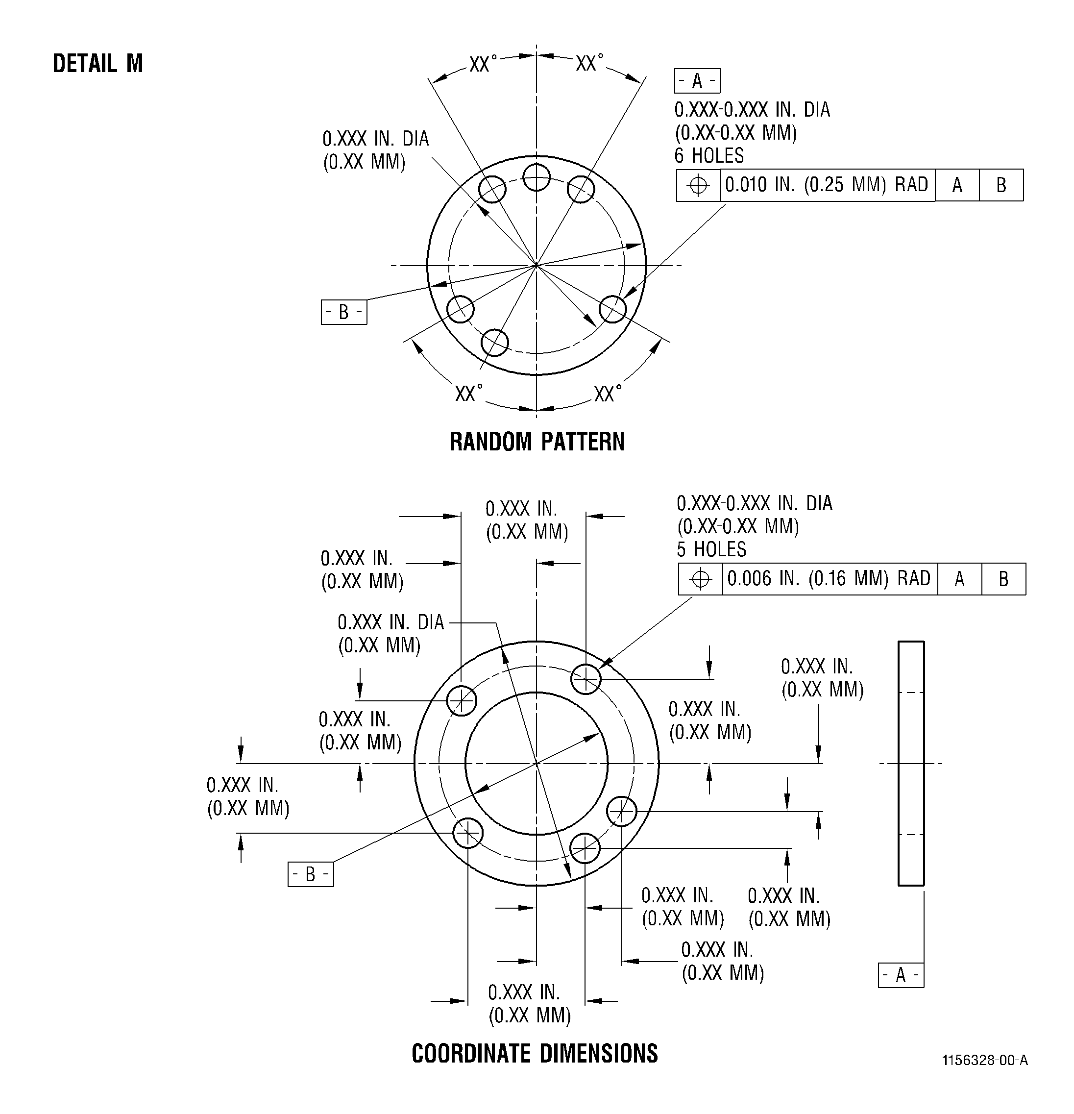
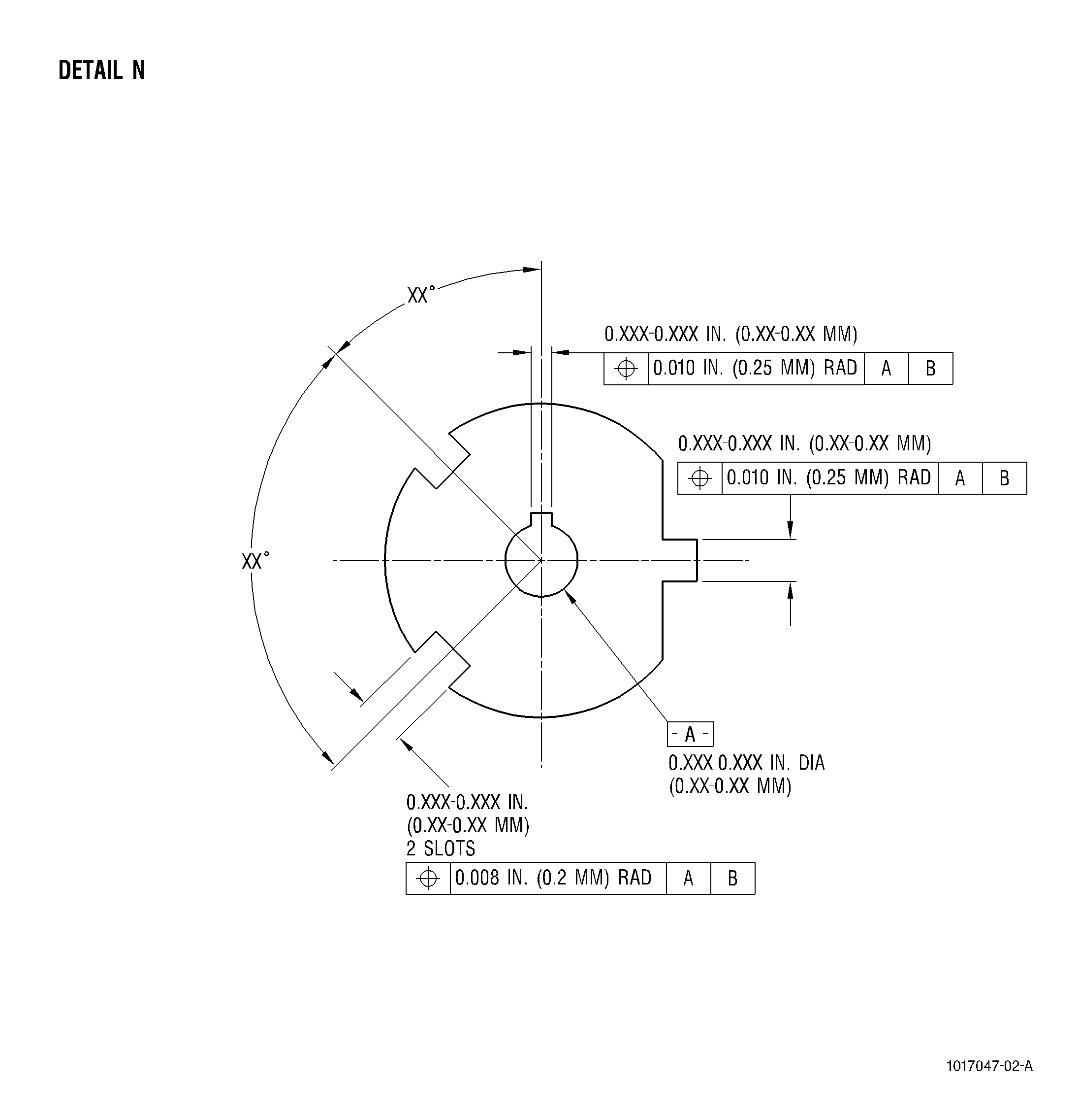
| (Refer to Details M and N,
|
|
| The exact location, which can be calculated with known data, of a point or series of points on a part. True position may be stated either as degrees of arc from an established point, or as coordinate dimensions from horizontal and vertical centerlines or other features.
|
|