| COMMERCIAL ENGINE STANDARD PRACTICES MANUAL | Dated: 04/01/2006 | |
| SPM 70-31-06 MACHINED FEATURES SHOP-RUN TOLERANCES | ||
| COMMERCIAL ENGINE STANDARD PRACTICES MANUAL | Dated: 04/01/2006 | |
| SPM 70-31-06 MACHINED FEATURES SHOP-RUN TOLERANCES | ||
| TASK 70-31-06-220-001 |
| 1 . | General. |
| A. | This Standard Practice gives the general instructions and shop-run tolerances for machined features produced by the document referring to this Standard Practice. The data given in this Standard Practice applies to machined features when: |
| (1) | The tolerances on form and position are not specified, and |
| (2) | The repair document or other approved document references this Standard Practice. |
| NOTE: |
|
| 2 . | Definitions |
| Subtask 70-31-06-220-002 |
| A. | Datum. |
| The reference surface, line, or point from which other geometric characteristics are located and measured. |
| B. | Nominal Thickness. |
| The value midway between the minimum and the maximum stock limits specified in the document or drawing. |
| C. | Surface Roughness. |
| Measured surface profile characteristics. Often referred to as the surface texture or surface finish. |
| NOTE: |
|
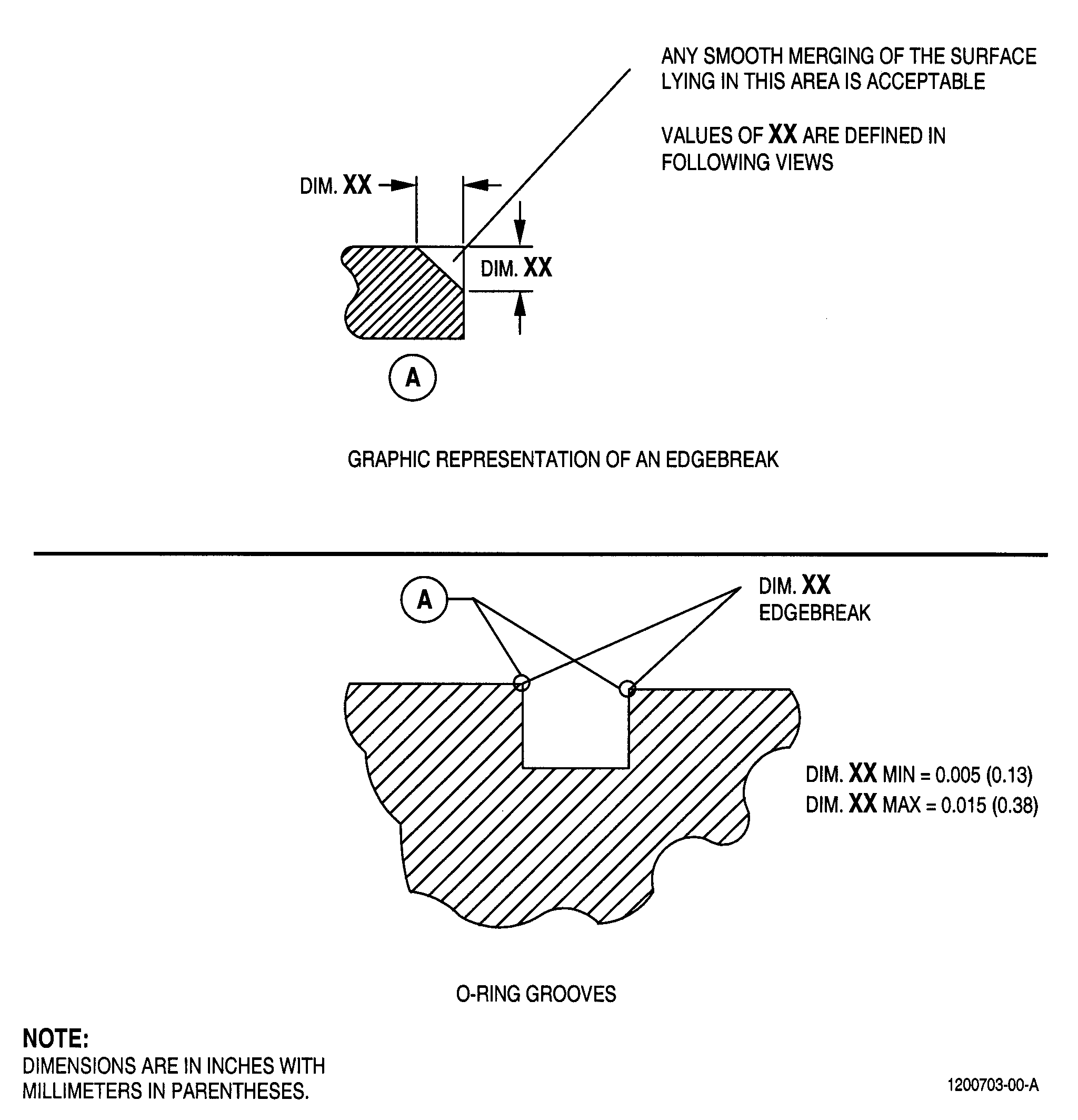
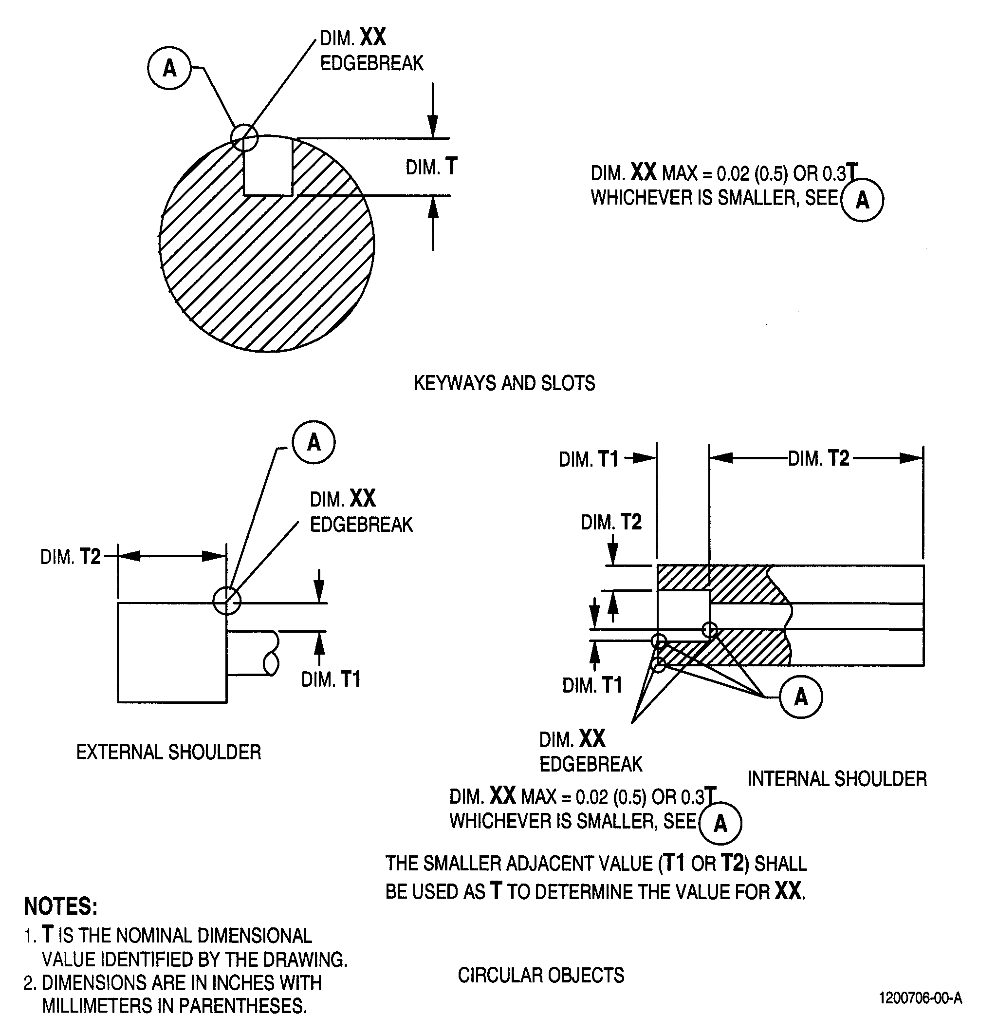
| D. | Edgebreak. |
| An edgebreak is the treatment necessary to a corner or intersection of two machined surfaces or a machined surface and any other surface. |
| 3 . | Requirements. |
| Subtask 70-31-06-220-003 |
| A. | Applicability. |
| The requirements of this Standard Practice are applicable to all machined features. For form and position tolerances of sheet metal parts not specified in the Engine/Shop Manual, refer to TASK 70-31-07-220-001, Sheet Metal Parts and Fabricated Assemblies Shop-Run Tolerances. |
| B. | Dimension Requirements. |
| Machined features must be to Engine/Shop Manual limits. If the Engine/Shop Manual does not specify the variations permitted for the conditions of form and position, the values specified here apply if this Standard Practice is referenced. |
| C. | Tolerance of Form and Position. |
| (1) | Run-Out. |
| The circular run-out of any diameter shown concentric about an axis must not be more than 0.005 inch (0.13 mm) full indicator movement (FIM) to other diameters shown concentric to that same axis. If a datum is in the figures, the run-out must be to that datum axis. |
| (a) | Other Regular Features. |
| The axis of other regular features must be concentric with each other and with other coaxial diameters to 0.005 inch (0.13 mm) dia. |
| (b) | Flatness, Straightness, True Contour. |
| Variation in flatness, straightness, and true contour must not be more than the values shown in Table 1. |
| (c) | Parallelism and Perpendicularity. |
| The elements of flat machined surfaces shown parallel or perpendicular and dimensioned from a common datum must be parallel or perpendicular to each other within the tolerance that follows: |
| For elements with a length of 20 inches (508 mm) and less: the total tolerance is 0.002 inch (0.05 mm) times the length, with a maximum of 0.015 inch (0.38 mm) total. |
| For elements with a length of more than 20 inches (508 mm): the total tolerance is 0.002 inch (0.05 mm) times the length with a maximum of 0.030 inch (0.76 mm) total. |
| For perpedicularity of threaded features, refer to Step 3.I.(2). |
| (d) | Run-Out - Circular (Face Run-Out). |
| The maximum circular run-out of circular element at right angles to its axis must not be more than the values shown in Table 2. |
|
|||||||||||||||||||||||||||||||||||||||||||||||||||||||||||||||||||||||||
| WARNING: |
|
| D. | Edgebreak Sharp Edges On Machined Surfaces. |
| Sharp edges, high metal, and burrs must be removed to prevent stress concentrations, to help safe handling, and to prevent mating parts from being cut and scored. After removal, the requirements of Figure 2 must be met. An inspection can be made by looking at visual standards. |
| WARNING: |
|
| (1) | Shot Peened External Corners. |
| For areas that you will shot peen, the edgebreak on all the external corners must be 0.015-0.030 inch (0.38-0.76 mm). Minimum or corner radius less than 0.015 inch (0.38 mm) is permitted if both of the conditions that follow are met: |
| (a) | Minimum edgebreak is greater than or equal to 0.005 inch (0.13 mm). |
| (b) | It is shown that corner rollover during shot peening does not occur at the minimum edgebreak condition. |
| (2) | Life-Limited Part Edgebreaks. |
| For life-limited parts the edgebreak requirements should be fully specified by the text or figure in the Engine/Shop Manual. Do not use the edgebreak requirements in this paragraph unless instructed by the Engine/Shop Manual. |
| E. | Blended Surfaces. |
| All connecting curved surfaces or curved and plane surfaces shown as tangent must be blended smoothly. |
| F. | Center Hole. |
| Center holes are permitted in flat end shafts and must be proportional in measure with the shaft end diameter. They are not shown on figures unless it is necessary to limit their size. |
| G. | Surface Roughness. |
| The surface roughness values listed in Table 3 apply as follows: |
| (1) | When the text or figures of the document referring to this Standard Practice do not specify a roughness height rating for these specific surfaces. |
| (2) | When these values specify a smaller roughness than the general roughness value specified in the document referencing this Standard Practice or if none is specified. |
|
|||||||||||||||||||||||||||||||||||||||||||||||||||
| H. | Spotface Instructions. |
| The diameter of spotface is given as the diameter of the flat, cleaned surface with the full-corner radius. Where the depth of the spotface is less than the corner radius, the full spotface diameter will not exist on the part. The minimum depth of a spotface shall be sufficient to cleanup at least 90 percent of the surface. The maximum depth of a spotface must not violate the minimum part thickness and must not be more than 0.02 inch (0.5 mm) deeper than the depth required for 90 percent cleanup. Refer to Figure 1 and to Step 3.J.(2) for positional tolerance requirements. |
| I. | Screw Threads. |
| (1) | Thread Length. |
| Thread length indicated in the text or figure is for minimum gage fit; incomplete threads beyond this point (for lead of tap or die) must conform to the applicable thread standard or specification. |
| (2) | Pitch Diameter. |
| The axis of both internal and external threaded features, as established by the pitch diameter, must be perpendicular to the face or shoulder within 30 minutes in any direction. |
| (3) | Threaded Inserts. |
| Threaded inserts must be installed with precision that will make the internal thread perpendicular to the face or shoulder of the parent material, within 1 degree in any direction. |
| J. | Holes. |
| (1) | Hole Centerline. |
| When a hole is dimensioned by other than the true position tolerancing method, (except as approved in Step 3.J.(2)), the hole centerline must be perpendicular to the face or the shoulder, within 1 degree in any direction. |
| (2) | Counterbores, Countersinks, Counterdrills. |
| Counterbores, countersinks, and counterdrills must be within a limit of 0.005 multiplied by the radius of the hole from the true position of the related hole. |
| (3) | Drill Point Depth. |
| The drill point depth must not exceed 0.5 times the nominal hole diameter. |
| 4 . | Visual Indications. |
| Subtask 70-31-06-220-004 |
| A. | Static (Non-Rotating) Metallic Items. |
| Visual flaws in machined surfaces of static (non-rotating) metallic items are acceptable when these conditions have been met: |
| (1) | They do not reduce the basic size (nominal) drawing thickness by more than 5 percent |
| (2) | Any adjacent high metal has been removed. |
| (3) | They are within the following limits and conditions. |
| (a) | Superficial Imperfections. |
| Superficial imperfections of no measurable depth such as burnish marks and evidence of contact with gages and fixtures are permitted. |
| (b) | Chatter Marks. |
| Tool chatter marks are permitted provided the surface roughness requirements are met. |
| (c) | Scratches. |
| Scratches are permitted within the following depth, surface roughness, and drawing characteristic limits, with the exception that scratches are not permitted on fuel and oil sealing surfaces. |
| 1 | Scratches up to 0.001 inch (0.03 mm) in depth are permitted. |
| 2 | Scratches up to 0.003 inch (0.08 mm) in depth are permitted where a surface roughness of 63 microinches (1.6 micrometers) or greater is permitted. |
| 3 | Scratches up to 0.005 inch (0.13 mm) in depth are permitted where a surface roughness of 125 microinches (3.2 micrometers) or greater is permitted. |
| (d) | Nicks. |
| Nicks are permitted within the following depths and conditions: |
| 1 | Nicks up to 0.001 inch (0.03 mm) in depth are permitted. |
| 2 | Nicks up to 0.005 inch (0.13 mm) in depth are permitted where a surface roughness of 63 microinches (1.6 micrometers) or greater is permitted. |
| (e) | Dents. |
| Dents or imperfections resembling dents are permitted as long as the diameter is no greater than 10 times the depth. |
| 1 | Dents up to 0.002 inch (0.05 mm) in depth are permitted. |
| 2 | Dents up to 0.005 inch (0.13 mm) deep are permitted where a surface roughness of 63 microinches (1.6 micrometers) or greater is permitted. |
| (f) | Spiral Tool Marks. |
| Spiral or circular tool marks less than 0.003 inch (0.08 mm) in depth are permitted in drilled holes. |
| B. | Rotating Metallic Items. |
| Visual flaws in machined surfaces of rotating metallic items are acceptable provided they are within the following limits and conditions. A rotating item is defined as an item that rotates about its own axis, coincident with the engine centerline. Airfoils (and the airfoil portion of blisks) are not rotating metallic items. |
| (1) | Superficial Imperfections. |
| Superficial imperfections of no measurable depth, such as burnish marks and evidence of contact with gages and fixtures, are permitted. |
| (2) | Excluded Features. |
| With the exception of superficial imperfections as defined in Step 4.B.(1), visual flaws are not permitted on the following features: |
| (a) | All features with a radius less than 0.500 inch (12.70 mm) in any direction, such as holes and fillets. |
| (b) | All features with a surface roughness of 32 microinches (0.8 micrometers) or less. |
| (c) | All axial and circumferential dovetail forms including load and lock slots. |
| (d) | Splines. |
| (e) | Both the large and small radii in compound fillets and shaped holes having at least one of the radii less than 0.500 inch (12.70 mm). |
| (f) | Bearing journal surfaces. |
| (g) | Disk bores. |
| (h) | Seal teeth. |
| (3) | Scratches. |
| Scratches in areas other than those defined in Step 4.B.(2) up to 0.001 inch (0.03 mm) in depth are permitted after any adjacent high metal has been removed. |
| (4) | Nicks. |
| Nicks in areas other than those defined in Step 4.B.(2) up to 0.001 inch (0.03 mm) in depth are permitted after any adjacent high metal has been removed. |
| (5) | Dents. |
| Dents in areas other than those defined in Step 4.B.(2) up to 0.001 inch (0.03 mm) in depth are permitted after any adjacent high metal has been removed. |
| WARNING: |
|
| (6) | Titanium alloy material removed by machining can bond back onto the machined surface. If you can see the material without magnification, the condition is unacceptable. |
| C. | Contamination. |
| None is permitted. All heat-treated parts must be clean and free from foreign material before any heat treatment operation. All cavities must be cleared of all chemical agents used during a repair of refurbishment immediately following each process. |
| D. | Discoloration. |
| Discoloration due to processing is acceptable, unless unapproved by the Engine/Shop Manuals. Discoloration due to other causes is not acceptable. |