| COMMERCIAL ENGINE STANDARD PRACTICES MANUAL | Dated: 01/31/2020 | |
| SPM 70-32-05 RADIOGRAPHIC INSPECTION | ||
| COMMERCIAL ENGINE STANDARD PRACTICES MANUAL | Dated: 01/31/2020 | |
| SPM 70-32-05 RADIOGRAPHIC INSPECTION | ||
| TASK 70-32-05-260-001 |
| 1 . | General. |
| A. | The radiographic inspection process is a nondestructive method of detecting flaws, cracks, corrosion, defects, wear, deformation, relative position, and presence of foreign bodies in an inspected part. The radiographic process employs X-rays, which are projected through the inspection part, forming an image on photographic film (radiograph) or captured as an image on filmless electronic imaging equipment which will show defects, etc. |
| B. | Radiographic inspection complements other methods of nondestructive inspection but does not replace them. |
| C. | Only experienced, certified inspectors shall be authorized to accept or reject parts on the basis of radiographic inspection. |
| D. | Personnel Requirements. |
| (1) | Personnel performing this inspection must be certified in accordance with National Aerospace Standard (NAS-410), American Society of Non Destructive Testing (ASNT-TC-1A), Air Transport Association Specification No. 105 (ATA 105), or locally approved certification program. |
| (2) | Personnel performing this inspection should receive practical training in the use of this procedure and must demonstrate proficiency in calibration of the inspection equipment, inspection of hardware, and evaluation of indications before the authority to accept and reject hardware is delegated. |
| (3) | Any training which may be provided regarding the performance of this inspection does not imply that the personnel who receive that training have met the requirements for inspector certification in accordance with NAS-410, ASNT-TC-1A, or ATA 105. |
| 2 . | Equipment. |
| Subtask 70-32-05-260-011 |
| A. | Because of the hazardous nature of X-rays, all equipment must be approved and certified by an approved agency for radiographic inspection. Maintenance and replacement of parts must be performed in accordance with instructions provided by the equipment manufacturer. Equipment that requires calibration or safety checks shall not be used when the calibration or safety tag is exposed, illegible or missing. |
| NOTE: |
|
| (1) | An X-ray generating unit of 300 KVCP (Kilo Volt Constant Potential) is required to inspect 1.25 inch (31.8 mm) thick steel. Greater thicknesses will require more powerful equipment. |
| (2) | Lead cones and filters made of various materials are used to vary X-ray exposure to produce the sharpest radiographic image under a variety of conditions. |
| (3) | The film holder holds a piece of film and protects it from light exposure. The film holder also holds optional lead screens in uniform contact with the film when specified. |
| (4) | The film viewer is used to examine the processed radiograph. The developed film is mounted on a translucent lighted surface which projects light through the film allowing it to be examined. The light intensity is adjustable and evenly diffused over the viewing surface. |
| (5) | The densitometer, the radiographic density step tablet, and the radiographic density comparator are used to establish the density of the inspection part and consequently help to determine accurate exposure and development time. |
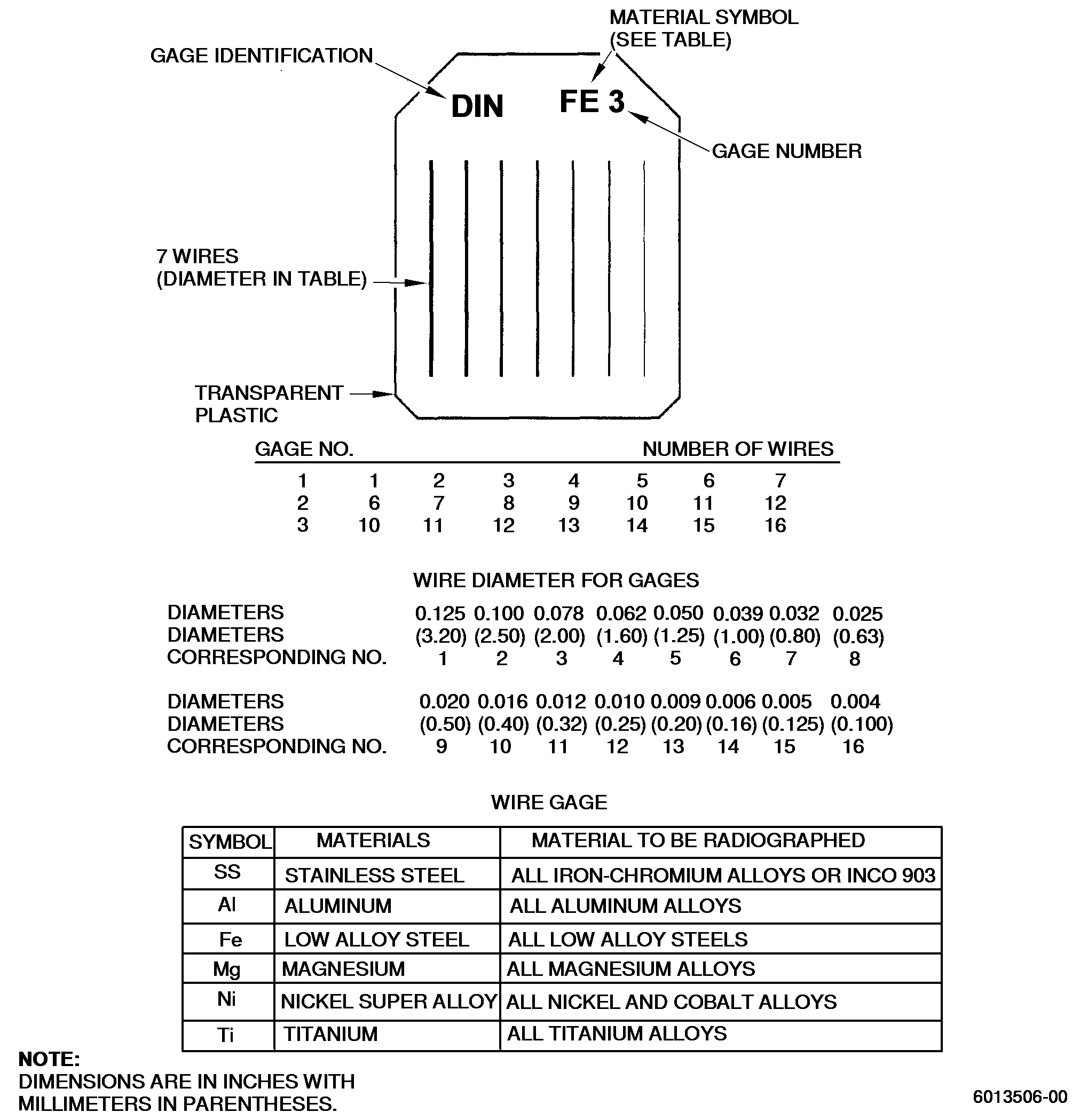
| (6) | Penetrameters, image quality indicators (IQI), and wire gages are used to measure image quality of radiographs. The material designated for the penetrameters, IQI, and wire gages are radiographically similar to the material being inspected and have approximately the same densities. Radiographically similar material refers to materials or alloys which have approximately the same radiation absorption. The identical alloy is not required. |
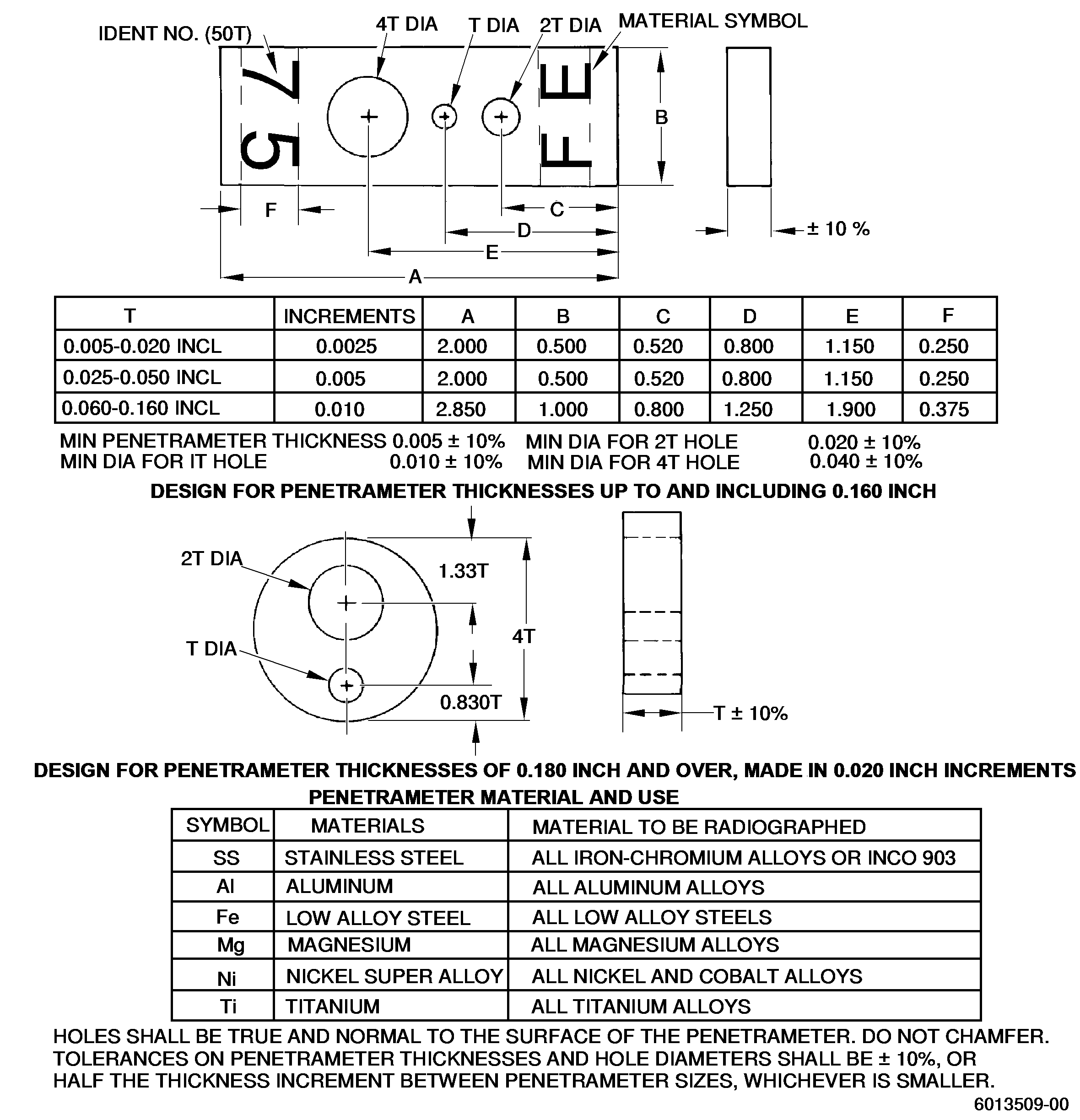
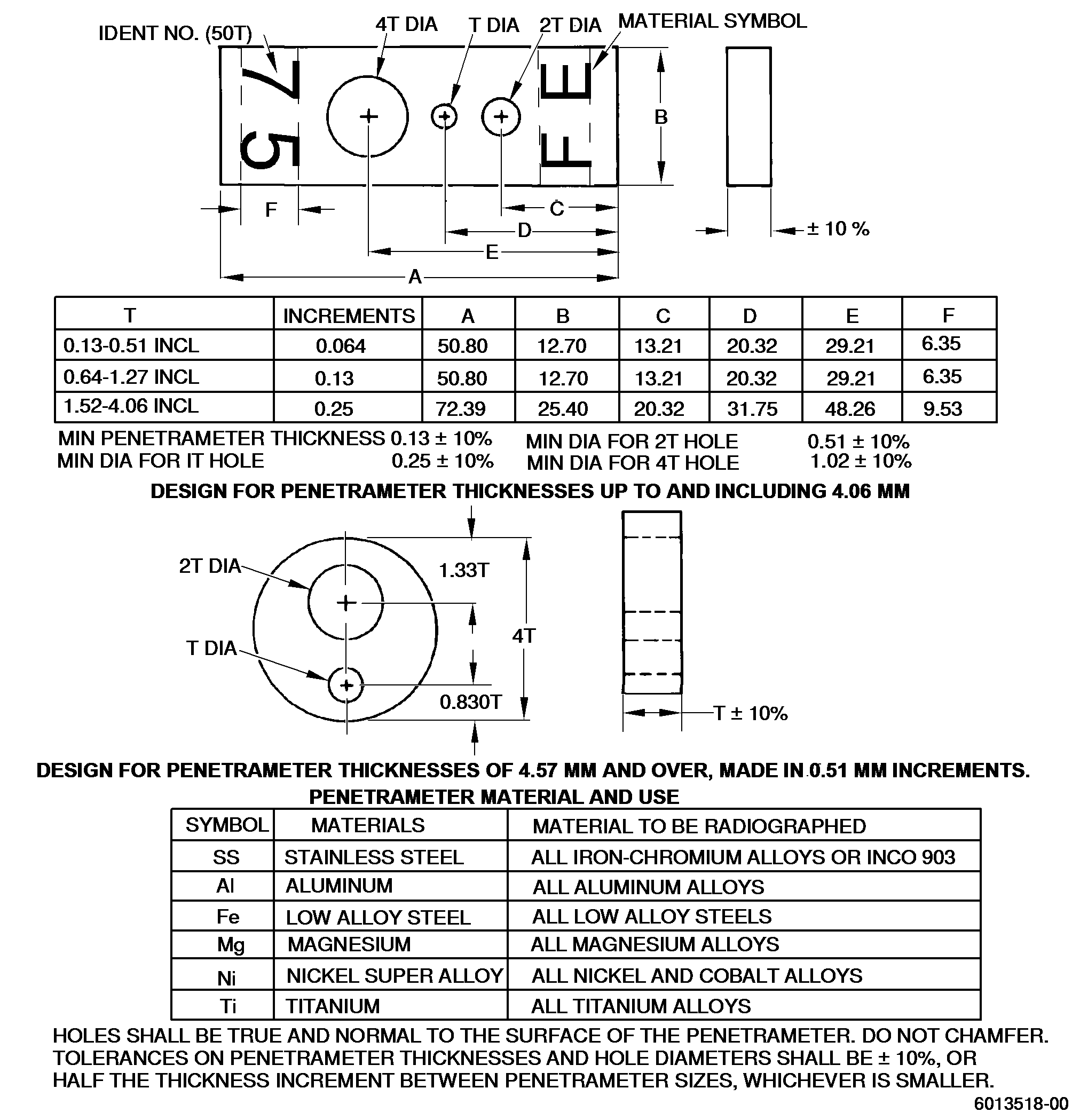
| (a) | Penetrameters and IQI are blocks of specified materials and thicknesses containing holes of specified sizes. |
| (b) | Penetrameters are manufactured to the requirements shown in Figure 3. The IQI are manufactured to the requirements of Figure 2. |
| (c) | The wire gage contains 7 wires of specified material and sizes and is manufactured to the requirements of Figure 1. |
| 3 . | Procedure. |
| Subtask 70-32-05-260-012 |
| A. | Film must be stored in a cool, dry area which is free from penetrating radiation. |
| CAUTION: |
|
| B. | Film must be handled by its edges, with clean, dry hands to avoid finger marks. Unexposed and unprocessed film shall be handled only in a dust-free photographic darkroom. An approved safelight may be used if desired. |
| WARNING: |
|
| C. | Film Exposure. |
| (1) | Settings for parts are obtained by estimate, trial, and correction until a satisfactory radiograph is obtained. These particulars are recorded on technique charts and filed by part identification for future reference. |
| (2) | The technique chart should include the following information: |
| (a) | Part number |
| (b) | X-ray unit identification |
| (c) | Milliamperage |
| (d) | Film exposure time |
| (e) | Cone |
| (f) | Angle |
| (g) | Kilovoltage |
| (h) | Filter |
| (i) | Screen remarks, sketches, etc. |
| (j) | Film size |
| (k) | Film type |
| (l) | Film focal distance: at least 36 inches (914 mm) |
| (m) | Focal spot size |
| (n) | Setup (cutting of film for separate exposures) |
| (o) | Cassette |
| (p) | Number of film frame |
| (q) | Identification of the film for part number and location of film on part |
| (r) | Penetrameter, IQI, or wire gage used (identity, size, and material) |
| (s) | Film processing time - temperature |
| (t) | Distance of film from inspection surface: must not exceed 1.5 inch (38 mm) |
| (u) | Specific remarks, sketches, etc. |
| (3) | Select the proper penetrameter, IQI, or wire gage based upon the material and thickness of area of part to be inspected. The penetrameter, IQI, or wire gage is then placed on the X-ray source side of the part to be inspected at the outer edge of the cone of radiation. |
| WARNING: |
|
| D. | Film Processing. |
| Following exposure, the film is developed, fixed, and washed in accordance with the manufacturer's instruction sheet. Accurate control of time and temperature is essential and all solution temperatures, including that of the wash-water, should be as near equal as practical. After removal of excess water, the film is dried rapidly in a well ventilated dust-free area. |
| E. | Density. |
| The H and D densities of the radiograph should be within a range of 1.5 - 4.0 in the area being interpreted, as read on the densitometer for radiographic density comparator. |
| F. | Interpretation. |
| Processed radiographic films are examined in a viewing room in which the light is subdued and shielded so that glare or reflections are not cast on the radiograph being examined. The screen of the viewer is shaded or masked so that direct light cannot shine around the radiograph and into the inspector's eyes. Films with a density of 2.2 or greater should be interpreted under high-intensity viewing illumination. Radiographs that show handling marks in the area of the part image should be discarded and remade. |
| 4 . | Quality Assurance. |
| Subtask 70-32-05-260-013 |
| A. | The penetrameter thickness and hole size defines the sensitivity or quality of the radiograph. The penetrameter used must have a thickness no greater than 2 percent of the thickness of the part being radiographed to a minimum penetrameter thickness of 0.005 inch (0.13 mm). The quality level of inspection must be2-2T which means that the image of the hole of 2T (twice the thickness of the penetrameter) and the outer edge of the penetrameter panel with a thickness of 2 percent of the part must be visible on the radiograph. The 2 percent refers to the first number in the quality level designation. |
| B. | The IQI is used in a similar method to define radiographic quality. The determination of the visibility index is obtained by counting the number of holes (a) visible on the radiograph, and by using the formula N = a-b. In this formula, b represents the number of holes which would be visible in all the steps with a thickness equal to or greater than 5 percent of the thickness being examined. The value of N can be negative, zero or positive. The sensitivity improves as the positive value of N increases. It should be noted that each group of small holes counts as only one unit in determining (a) and (b). N = value of 1.25 is approximately equivalent to a quality level of 2-2T when penetrameters are used. |
| C. | For the inspection of welds, it is sometimes preferable to use wire gages. The image quality is given by the thinnest wire still distinguishable on the radiograph, assuming that the indicator was placed during the exposure, between the source of radiation and the object being inspected and in close contact with the latter. The number of this wire is the measure of the image quality, which is preceded by the letters BZ. |
| D. | For inspection of electronic beam welds, the X-ray techniques shall recognize the weld preparation angles and have the capability to accurately control that angle during inspection. To establish the best possible angle for exposure during X-ray inspection, a part tacked, clamped, or similarly assembled and ready to weld shall be X-rayed to determine what angle shows the non-fused joint the sharpest, commonly referred to as "Black Line" X-ray. This angle ± 2 degrees shall then be used after welding for inspection. |
| E. | If filmless imaging equipment is used in place of conventional film, the results of the two methods must correlate. Record retention of the correlation must be maintained. Image processing capabilities such as frame averaging, subtraction, summing, filtering, etc. may be used. When permanent records are required, a back-up copy saved on a different system or media shall be maintained. |
| F. | Unless otherwise instructed by the process document, penetrameters are not required for the inspection of braze joints where the purpose of the inspection is to find whether material is present or absent. |