| COMMERCIAL ENGINE STANDARD PRACTICES MANUAL | Dated: 01/28/2020 | |
| SPM 70-32-06 ULTRASONIC INSPECTION | ||
| COMMERCIAL ENGINE STANDARD PRACTICES MANUAL | Dated: 01/28/2020 | |
| SPM 70-32-06 ULTRASONIC INSPECTION | ||
| TASK 70-32-06-270-001 |
| 1 . | General. |
| A. | The ultrasonic methods of nondestructive testing are used to inspect engine components to determine if the parts contain discontinuities or defects which could affect the life or use of the part or to validate repairs such as various bonding procedures. |
| B. | There are 2 basic types of ultrasonic testing; the pulse-echo A scan test and the through-transmission or pitch-catch test. |
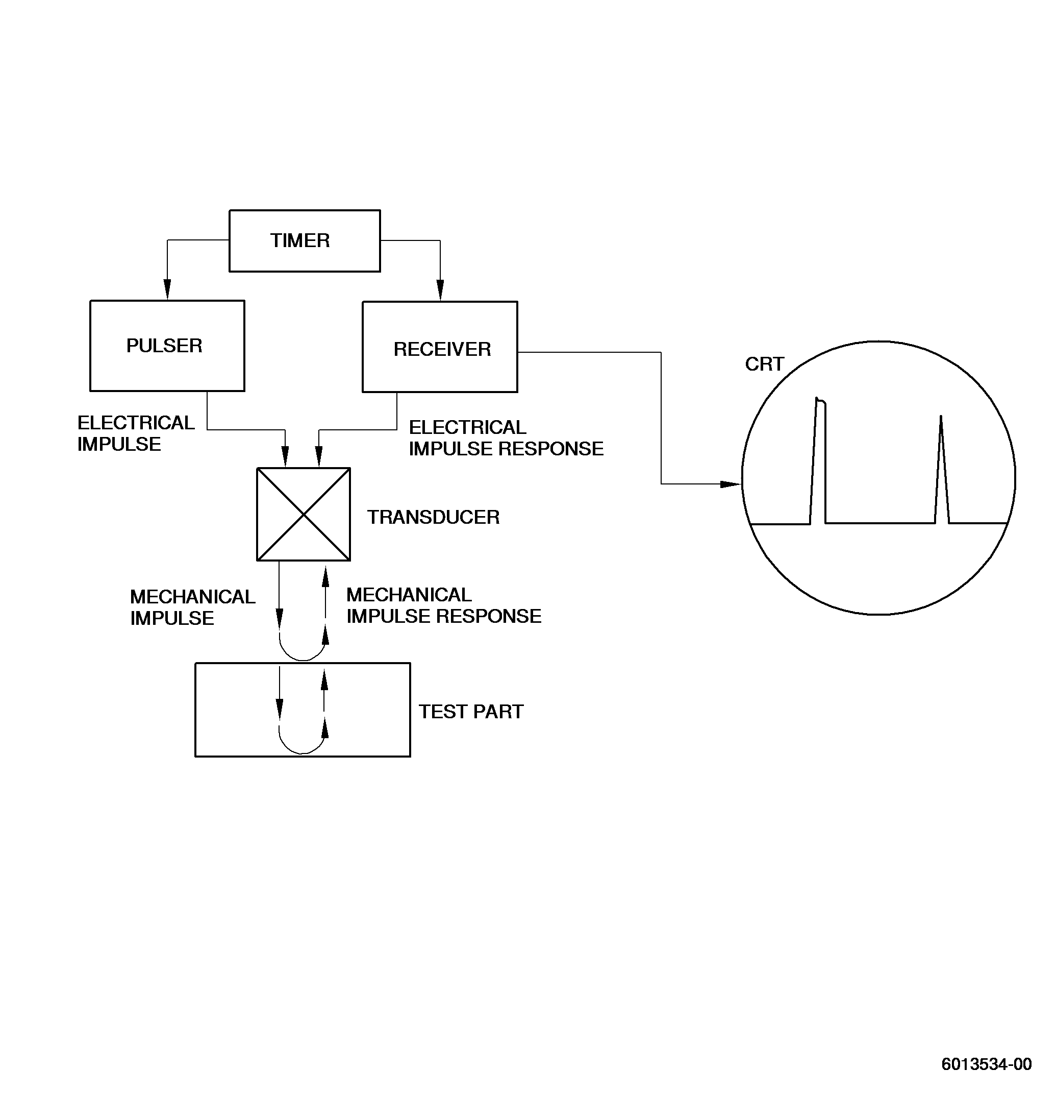
| (1) | In pulse-echo A scan testing, specific test apparatus converts electrical energy into short pulses of high frequency sound waves. These sound waves are then transmitted to the hardware to be inspected by means of coupling medium or couplant. After passing through this couplant the sound waves continue into or through the hardware and are altered or reflected by sonic reflectors (flaws or back surfaces) back through the couplant and into the ultrasonic receiving element. This sound wave pattern is then processed by the ultrasonic instrument and is observed by the inspector through the use of a cathode ray tube (CRT). Recording equipment or other monitoring facilities may be used to modify this basic system and to provide permanent documentation of inspection results. See Figure 1. |
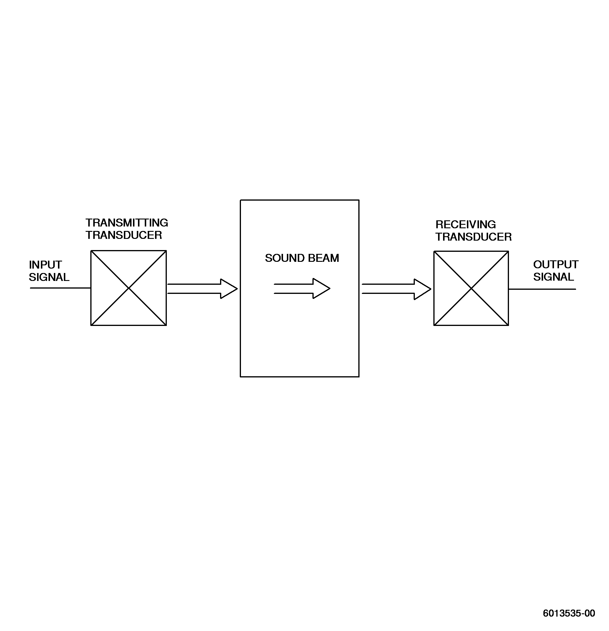
| (2) | In through-transmission or pitch-catch type of testing2 transducers are used. Accurate positioning of the receiving transducer is required to assure the proper capture of transmitted energy. See Figure 2. |
| C. | Contact testing and immersion testing are the 2 basic ultrasonic testing techniques. |
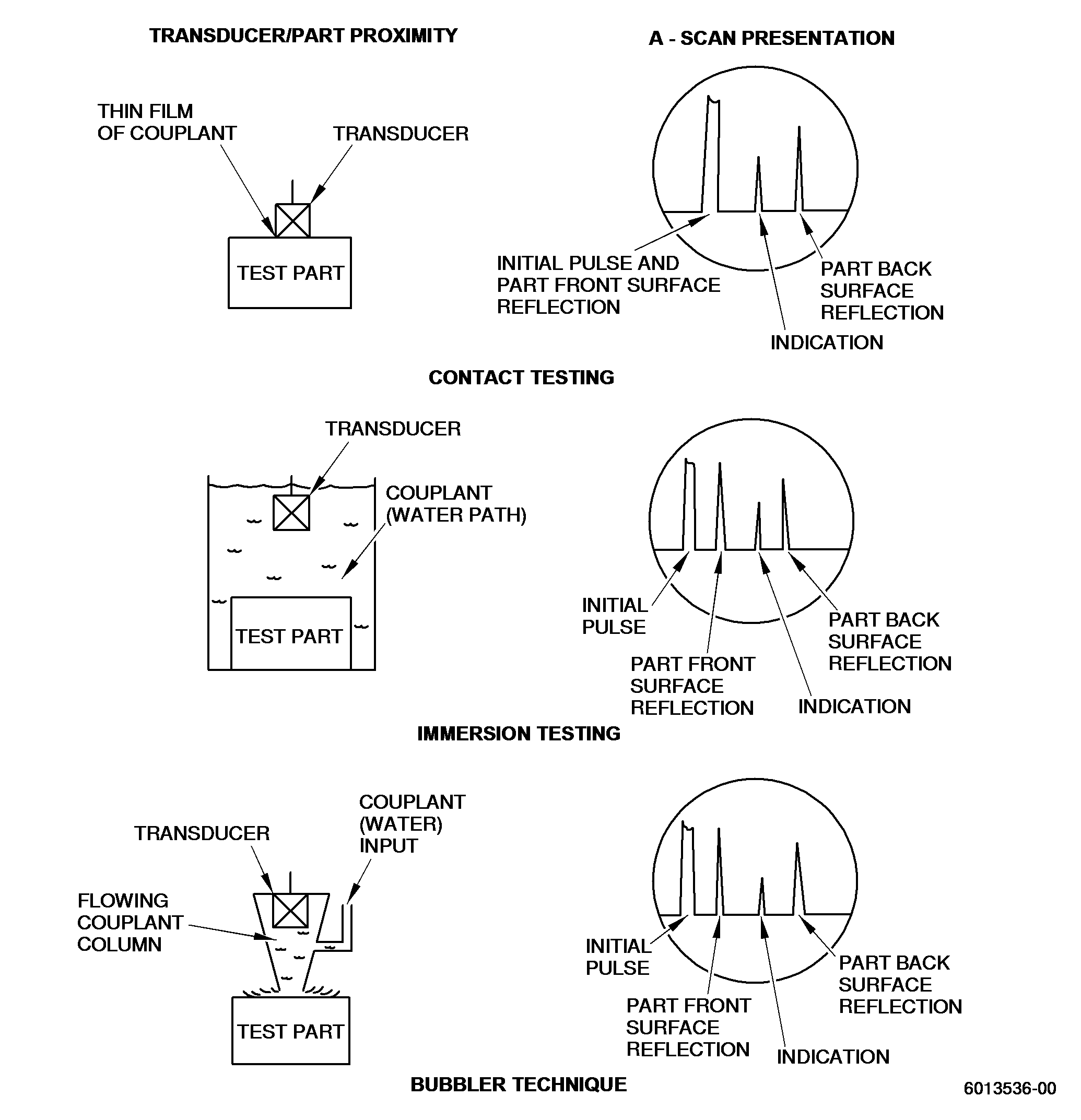
| (1) | Immersion testing is the generally applied inspection process. During immersion testing a waterproof transducer is used at a distance from the test part. The ultrasonic waves are then transmitted into the material through the liquid medium (couplant). The distance between the transducer and the part surface now appears on the CRT display as a wide space between the initial sonic pulse and the front surface reflection. In standard immersion testing both the transducer and the hardware are immersed in the couplant, usually water. This permits easy changes in sonic incident angles and allows mode changes by angulating either the hardware or the transducer holder (manipulator). However, a disadvantage to this system is the need for a tank sufficiently large enough to submerge both the transducer and hardware. See Figure 3. |
| (2) | In contact testing the transducer is used with a very thin film of couplant between the transducer assembly and the test part. The CRT display from a contact system usually shows the initial sound pulse from the transducer and the front surface reflection as superimposed or very close together. Contact testing can be complicated by the inability to maintain a constant and uniform coupling between the transducer assembly and the test part. Different test part contours and/or sonic propagation directions or modes usually require different transducer assemblies to ensure contact with test part surface. Contact testing is limited to those components and tasks where the specific test method, equipment, transducers, etc., have been judged to be suited for this inspection task. |
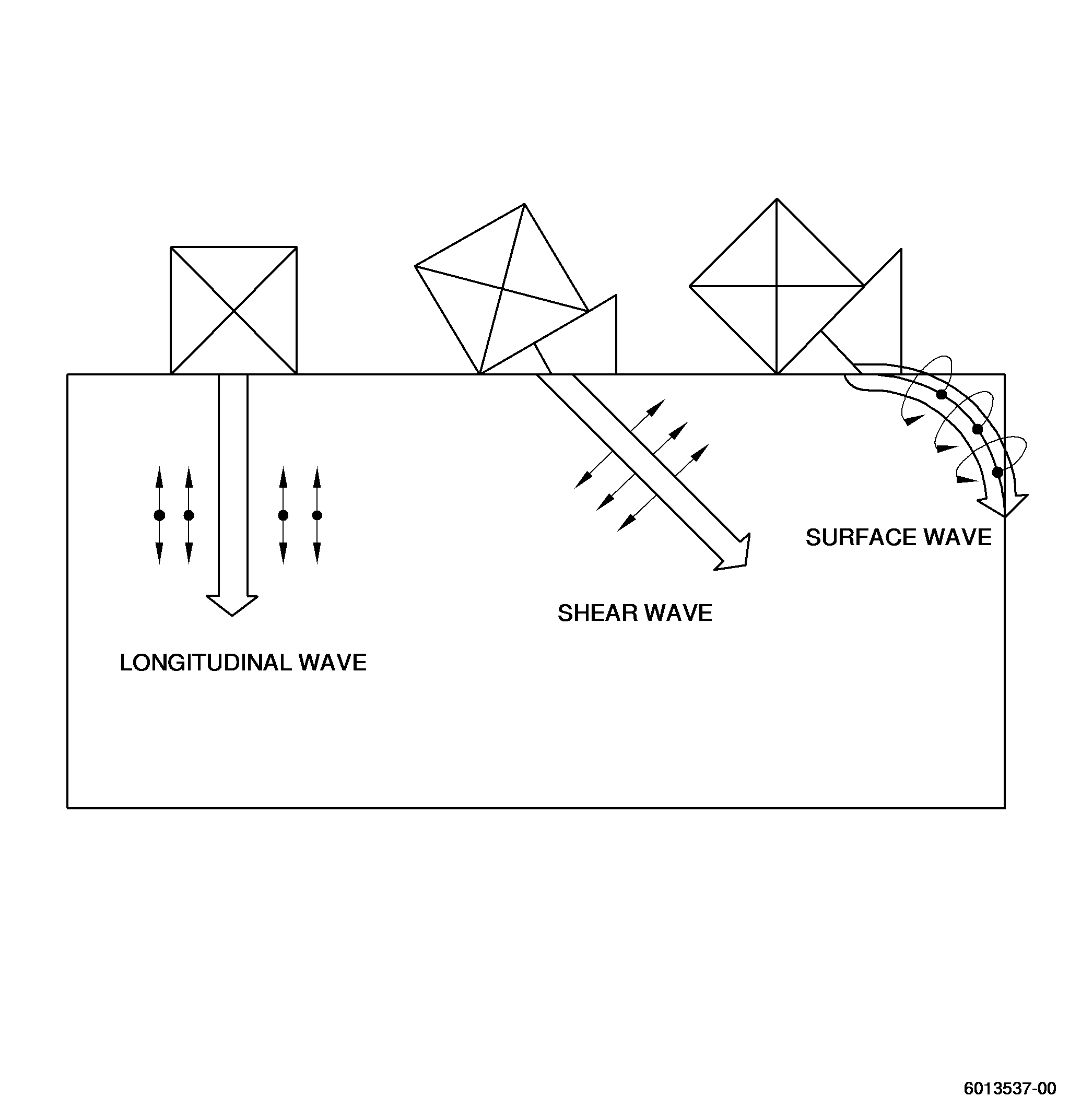
| D. | The 3 primary modes of sonic wave propagation used during ultrasonic inspection are: longitudinal, shear, and surface wave. Longitudinal or compression waves have particle vibrations in the same direction as the sound motion. Shear or transverse wave particle vibrations are at right angles to the sound motion. Surface or Rayleigh waves produce an elliptical shear wave form that moves along the free boundary or surface of a solid and is normally confined to a penetration depth of approximately 25 percent of a wave length. See Figure 4. |
| E. | The following equation, an adaptation of Snell's Law, is used to calculate incident angles, refracted angles, and modes: |
| Sin Angle1 = V1 divided by V2 |
| Where: |
| Angle1 = the incident angle of the beam from normal |
| Angle2 = the refracted beam angle in the test material |
| V1 = the velocity of sound in the first medium |
| V2 = the velocity of sound in the second medium |
| Maximum reflection from a sonic reflector is achieved when the reflector surface is 90 percent or perpendicular to the sound propagation direction. |
| F. | When an ultrasonic wave that is traveling through one medium reaches a boundary between it and a second medium, part of the energy continues through the second medium while the remainder is reflected back into the first. The characteristics of each material that determines the amount of reflection is known as the acoustic impedance (z) of the material and is a product of the density of the material (p) and velocity of sound in the material (v), (z = pv). In a pulse-echo system the ultrasonic waves pass through an interface twice, once in each direction. If the second medium is air almost100 percent of the sound energy will be reflected back into the first medium. |
| If the second medium is not air a different percentage of sound energy will be reflected back toward the first medium. Acoustic impedance may be matched and reflection reduced by keeping the impedances the same, however, it is normally necessary in ultrasonic testing to transmit sound energy between mediums of greatly different acoustic impedances and some method must be available to accomplish this. The best method of reducing impedance mismatch is the liquid couplants. |
| G. | The couplant couples the sound energy transmitted from the transducer to the test part. There is a wide range of couplants including liquids, pastes, and semi-liquids that fulfill the following requirements: |
| (1) | The couplant should have an acoustic impedance between that of the transducer face and the test specimen. |
| (2) | The couplant should be harmless to the part, easily applied, viscous, easily removed, free of air bubbles and homogeneous and should theoretically wet both the transducer face and specimen surfaces. Water, tap or with a wetting agent added, is commonly used for immersion testing and the more viscous oils, glycerine or other commercially available products, are used during contact testing. |
| H. | Only experienced, qualified operators designated and approved to perform this specific ultrasonic inspection shall perform the test. Operator must be capable of performing equipment calibrations, carry out the intended inspection and be capable of correctly interpreting test data before accepting or rejecting inspected parts. |
| I. | Personnel Requirements. |
| (1) | Personnel performing this inspection must be certified in accordance with National Aerospace Standard (NAS-410), American Society of Non Destructive Testing (ASNT-TC-1A), Air Transport Association Specification No. 105 (ATA 105), or locally approved certification program. |
| (2) | Personnel performing this inspection should receive practical training in the use of this procedure and must demonstrate proficiency in calibration of the inspection equipment, inspection of hardware, and evaluation of indications before the authority to accept and reject hardware is delegated. |
| (3) | Any training which may be provided regarding the performance of this inspection does not imply that the personnel who receive that training have met the requirements for inspector certification in accordance with NAS-410, ASNT-TC-1A, or ATA 105. |
| 2 . | Equipment. |
| Subtask 70-32-06-270-011 |
| A. | Ultrasonic test equipment generally consists of the following items. Manufacturer's instructions should be consulted for specific equipment being used. |
| (1) | The ultrasonic instrument generates electrical pulses, receives return information in the form of small amplitude voltages, amplifies the signals, and displays the signal as vertical deflections on the CRT. It contains the power supply to furnish the proper current requirements and the timing mechanism which controls and synchronizes the pulse rate, sweep, and time delay circuits. |
| (2) | The transducer is the pulsing and sensing portion of the system. It is the unit that makes generation and detection of sound energy possible. It consists of a piezoelectric crystal mounted in a housing assembly, with an electrode connecting the crystal to the housing cable connector. The majority of piezoelectric crystals in use are made of lithium sulfate. |
| Quartz and barium titanate are 2 other crystal materials commonly used. The frequency range of ultrasonic transducers used for flaw detection is 500,000 cycles per second to 25,000,000 cycles per second. |
| (3) | Manipulators for parts or transducers are incorporated in most ultrasonic test systems to change the angular orientation of the ultrasonic beam with respect to the test specimen. This orientation is required to achieve proper introduction of the sound into the part being tested, and is dependent upon the part geometry, the nature of the defect, and the expected defect orientation in order to obtain the maximum sound energy reflected to the transducer for greatest defect detectability. |
| (4) | Recording equipment may be used to provide permanent records of inspection results. |
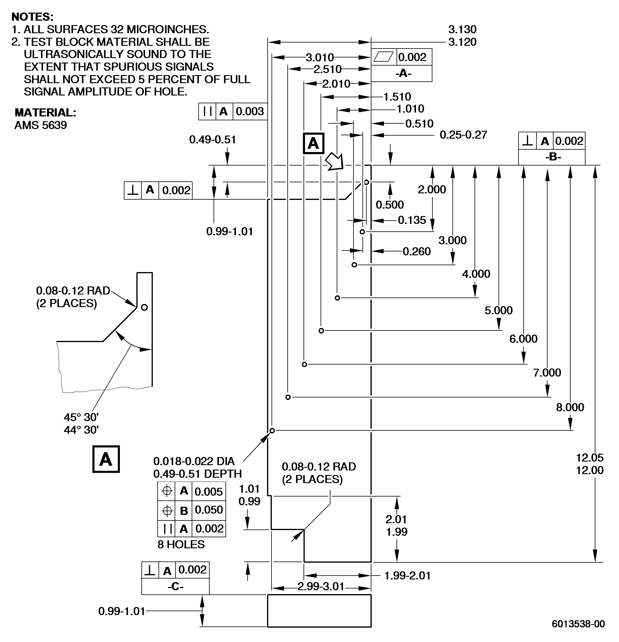
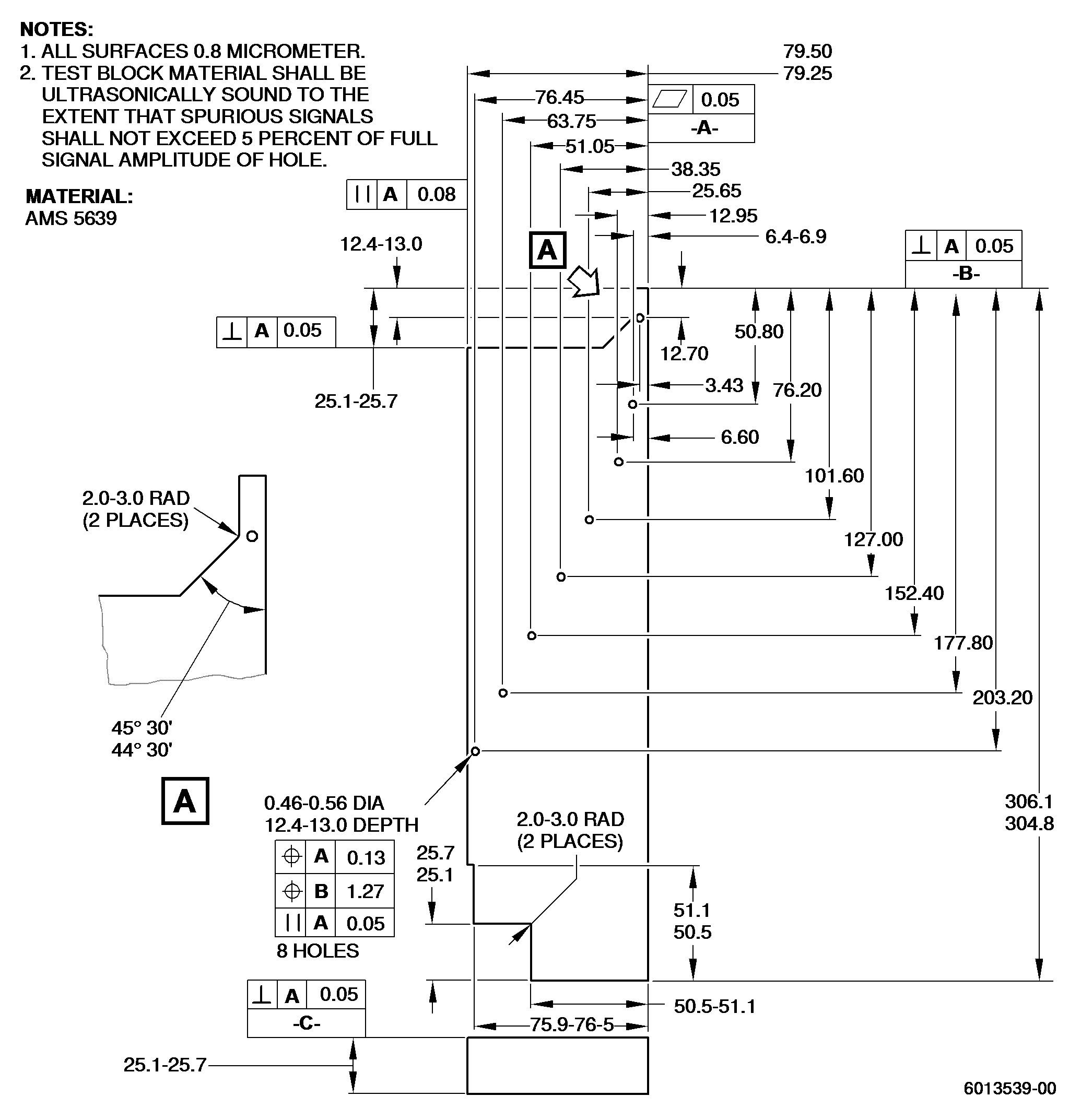
| (5) | Calibration standards are used in ultrasonic testing for calibrating equipment by providing reproducible references for establishing system sensitivity and by verifying that the test system is functioning properly. Calibration standards are normally fabricated from material that is acoustically similar to the part to be inspected. Typical sonic reflectors used for calibration standards are: back surfaces, side of a hole, end of a flat-bottom hole, or notches. See Figure 5. |
| 3 . | Procedure. |
| Subtask 70-32-06-270-012 |
| A. | Inspection plans or operation sheets should be prepared that define inspection parameters and procedures, including rejection criteria, part disposition, calibration requirements, etc., prior to the inspection of the part. Records should be kept and maintained that reflect compliance with the test requirements and this practice. |
| B. | Normally inspection calibrations are performed before and after the inspection of each part. If a series of inspections are performed, calibration may be performed at the beginning or end of the series, but should not be greater than 8 hours between calibrations. |
| (1) | Generally if calibration signals vary by greater than 10 percent full scale, all material inspected during the interim period should be reinspected. However, if the calibration response has increased by more than 10 percent full scale, the hardware need not be reinspected as the system would have been more sensitive than required. |
| (2) | During the immersion inspection of forging and certain other applications, calibration is achieved by setting the response signal from one or more 0.020 inch (0.51 mm) side drilled holes to 80 percent full scale amplitude. The distance of the hole(s) below the surface being inspected should correspond to the depth of material to be inspected and allow the necessary resolution. |
| (3) | In other tests the calibration standard normally represents the condition in which the test is being conducted. When specific flaw standards are used as a base for calibration, they should represent the approximate limiting condition to be used for part acceptance. |
| C. | Part surfaces must be clean and free of any oxides, scales, loose foreign material, or machining grooves which could interfere with the intended inspection. Reference points or other techniques for identifying and marking ultrasonic conditions of interest with respect to part position must be identified and used. |
| D. | Maximum scanning index and speeds shall be no greater than that established for specific technique and shall assure acceptable inspection coverage and detectability. In most inspections the maximum scanning index intervals shall be 75 percent of the effective beam width. With positioning accuracy of 0.01 inch/feet (0.25/304.8 mm) and a spiral index, the scanning index may be increased to 100 percent of the effective beam width. Without a spiral index, it shall be no more than 90 percent. |
| E. | Lineal surface speed during visual inspection shall be no more than 6 inches (15.24 cm) per second. Lineal surface speed during recording shall be determined by the operating characteristics of the equipment. During surface wave contact testing the transducer is normally indexed and simultaneously rotated about its axis to conduct a thorough search of the inspection area. |
| 4 . | Quality Assurance. |
| Subtask 70-32-06-270-013 |
| A. | Calibrations and calibration checks shall be performed at intervals that assure any part inspected to an improper calibration can be reinspected before any additional processing of the part that would limit or compromise its reinspection. |