| COMMERCIAL ENGINE STANDARD PRACTICES MANUAL | Dated: 04/01/2006 | |
| SPM 70-34-04 PORTABLE ROCKWELL HARDNESS TESTING | ||
| COMMERCIAL ENGINE STANDARD PRACTICES MANUAL | Dated: 04/01/2006 | |
| SPM 70-34-04 PORTABLE ROCKWELL HARDNESS TESTING | ||
| TASK 70-34-04-220-010 |
| 1 . | General. |
| A. | Portable hardness testing equipment is used when the weight, shape, or condition of a test part prevents testing by other methods. |
| B. | The portable hardness tester is not considered to be a precise measuring device and should not be used as the only instrument for acceptance without meeting all requirements in the calibration section. |
| C. | The Rockwell hardness test uses a calibrated machine to force a penetrator into the surface of the material being tested while measuring the permanent depth of the impression under minor and major loads. |
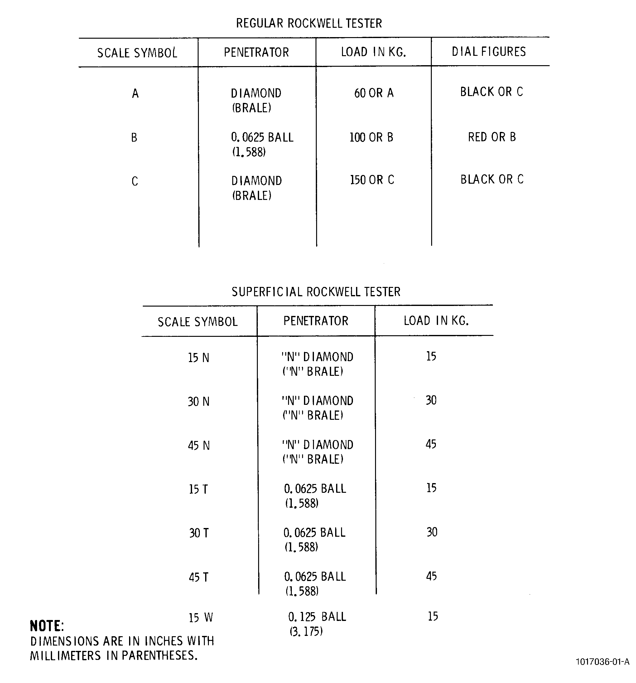
| D. | Both regular and superficial Rockwell hardness tests can be performed on the portable machine. The regular hardness test applies a minor load of 10 kilograms force (kgf) and major loads of 60, 100, or 150 kgf. The superficial hardness test applies a minor load of 3 kgf and a major load of 15, 30, or 45 kgf. |
| E. | The portable hardness tester is equipped with a means of attaching it to the surface to be tested. The indenting force may be applied using a hydraulic cylinder equipped with a pressure gage or using a screw through a calibrated spring with a dial gage. |
| F. | The portable tester utilizes a diamond penetrator or a 1.588 mm steel ball. See Figure 1. |
| G. | The machine backs up the part to be tested with an anvil. The 3 anvils available are shown in Figure 1. The proper anvil should be selected to completely support the test part while the surface to be tested is parallel to the anvil surface and perpendicular to the penetrator. |
| 2 . | Equipment. |
| Subtask 70-34-04-220-101 |
| A. | Portable Hardness Tester. |
| B. | Penetrator. |
| (1) | Diamond sphero-cone. |
| (2) | 1.588 mm steel ball. |
| C. | Anvil. |
| (1) | Plane anvil. |
| (2) | Convex anvil. |
| (3) | Shallow "V" anvil. |
| D. | Hardness Test Blocks. |
| E. | Calibrate Tester as Follows: |
| CAUTION: |
|
| (1) | Take 5 readings on test block. |
| (2) | Test blocks should be in the same hardness range ( 10) as the part to be tested. |
| (3) | Adjust machine so that the median of the 5 readings will not differ from test block nominal value by more than 2.0 hardness points. |
| 3 . | Materials. |
| Subtask 70-34-04-220-102 |
| A. | None required. |
| 4 . | Procedure. |
| Subtask 70-34-04-220-103 |
| A. | Establish type of test (regular or superficial) and scale to be used from the process document. Load and penetrator are determined by the designated scale. See Figure 2. |
| B. | Select an anvil to completely and rigidly back up the shape of the part being tested. |
| C. | Establish test conditions, if not otherwise specified in the Engine/Shop Manual, as follows: |
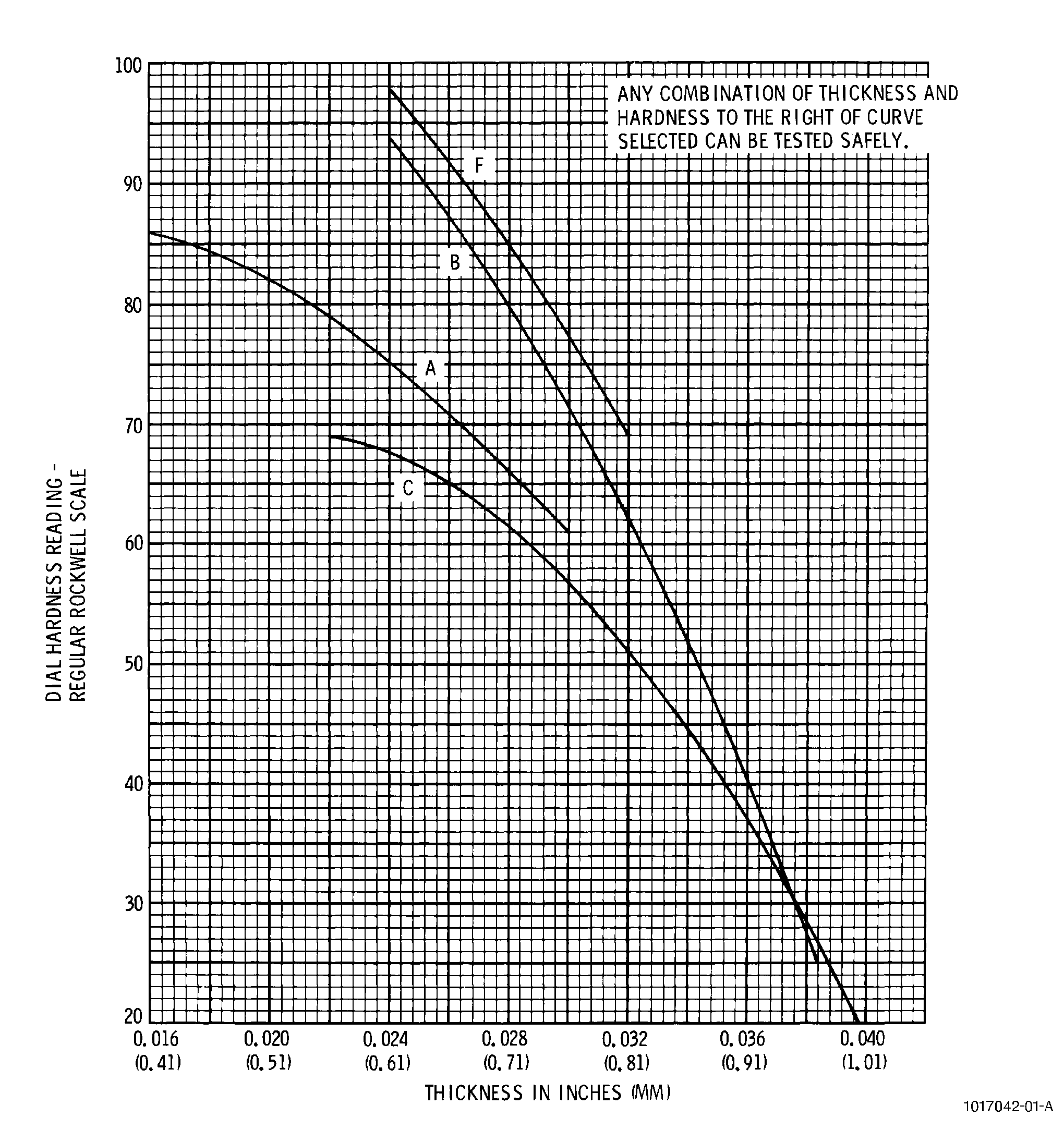
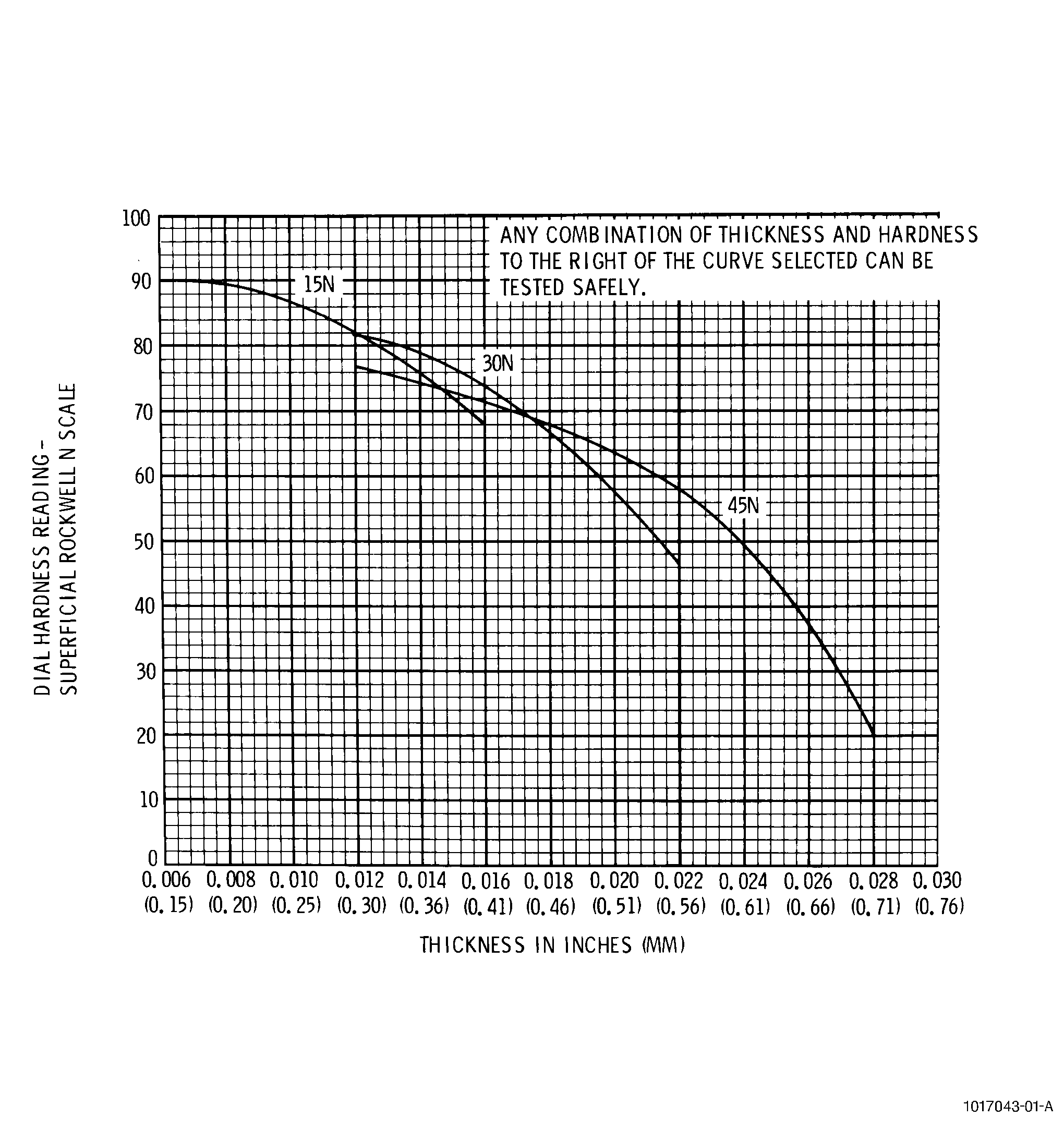
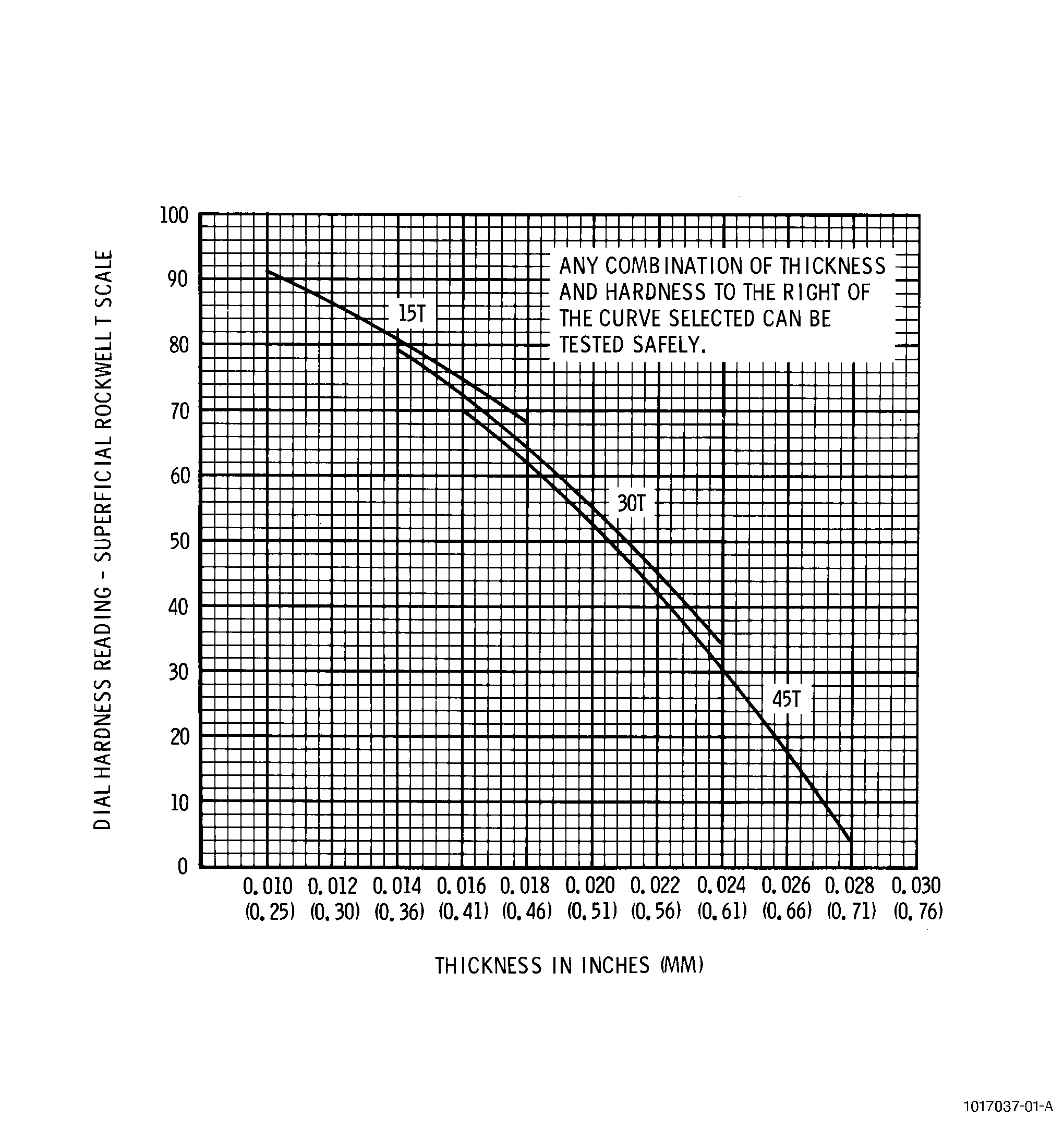
| (1) | Ensure that the part to be tested is thick enough to avoid having the penetrator impression show on the anvil side of the part. See Figure 3, Figure 4, and Figure 5. |
| (2) | Select sufficiently even, flat surface of part to enable the dimensions of the imprint to be accurately determined. |
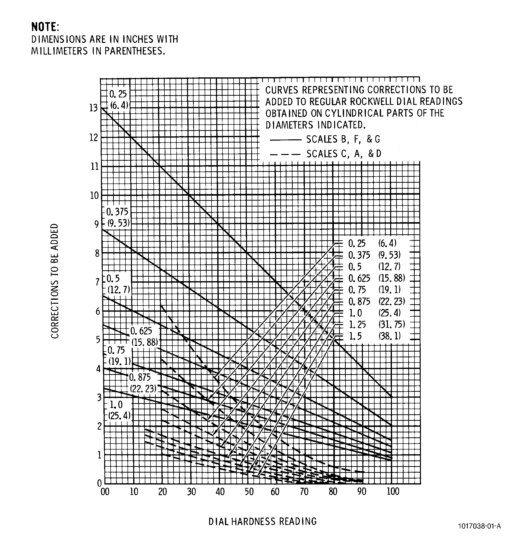
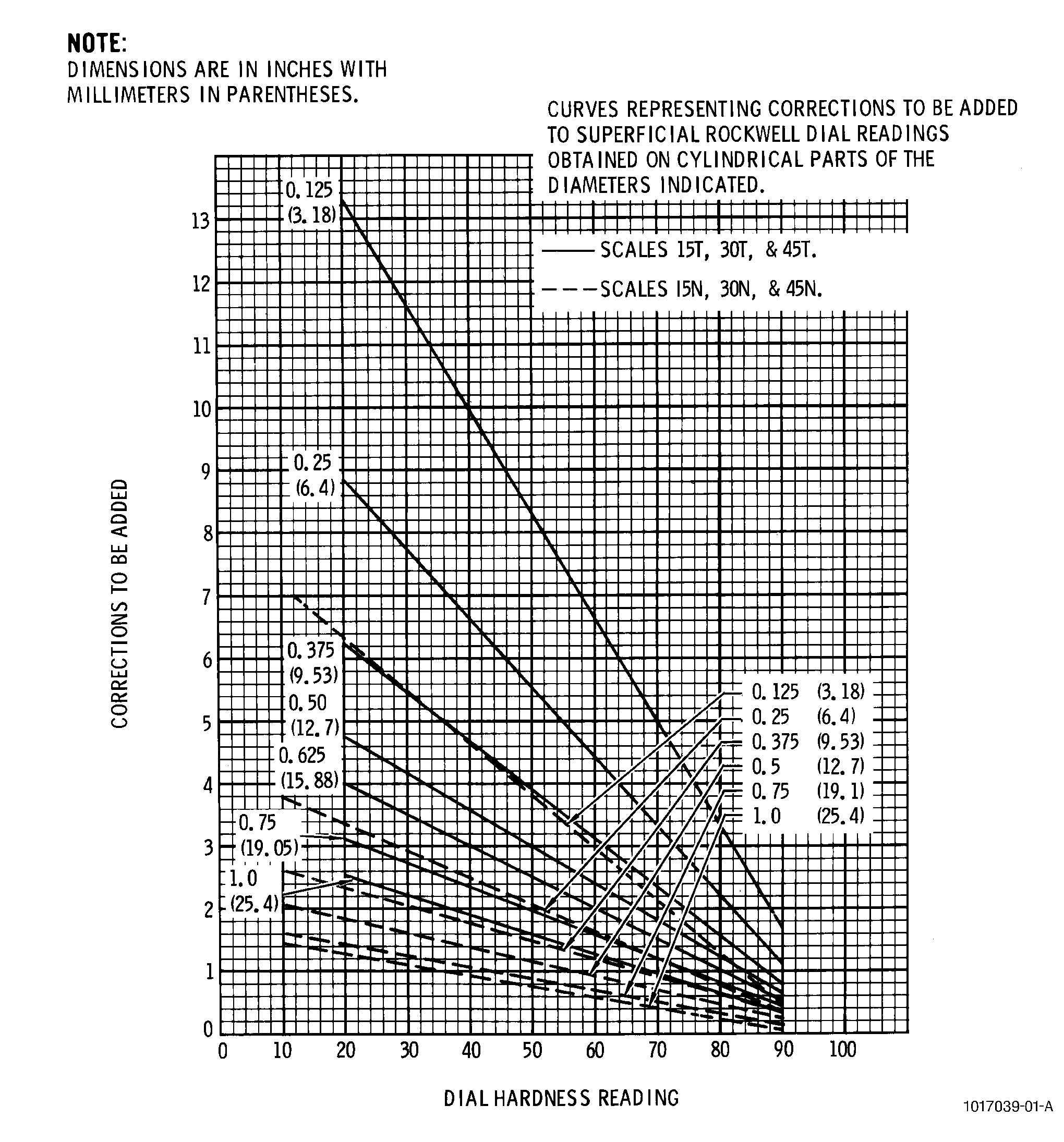
| (3) | If the surface of the part to be tested is curved, ensure that the concave side of the curved surface faces the penetrator. Use Figure 6 and Figure 7 for correction factors with the readings. |
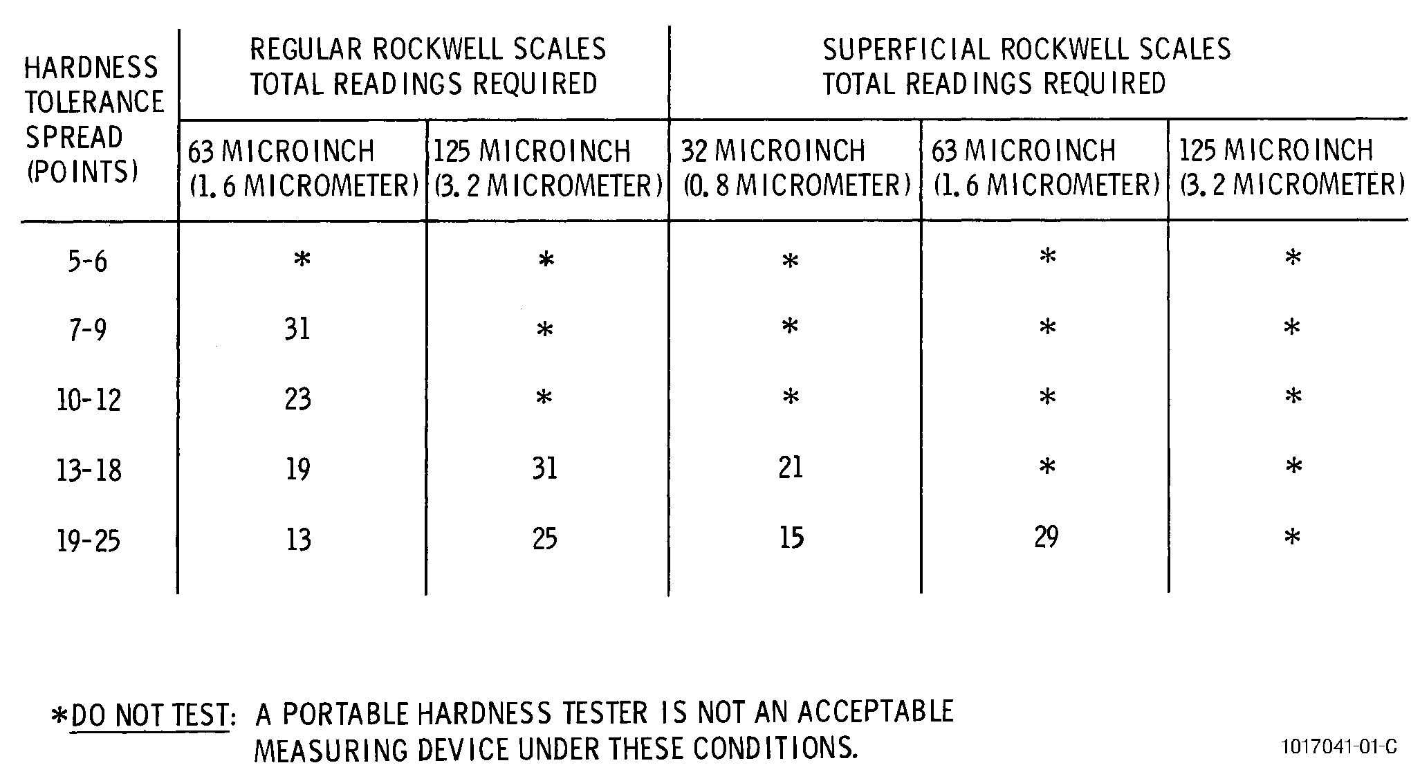
| (4) | Determine the number of readings to be taken according to Figure 8, for the surface finish of the part. |
| (5) | Inspect penetrator for defects and replace as necessary. |
| (6) | Ensure that the surface of the part to be tested is perpendicular to the axis of the penetrator. |
| (7) | Ensure that the test surface and machine contact surfaces are clean and free from oxidation and from foreign matter. |
| (8) | Position part to be tested and tester so that indentations are no closer to each other or to the edge of the part than 2.5 indentation diameters. |
| D. | Securely attach tester to surface to be tested. |
| WARNING: |
|
| E. | Perform test using scale indicated in process document. |
| (1) | Do not use the first reading after changing machine setting, anvil, penetrator, or testing at a different hardness range. |
| (2) | Apply major load for 2 seconds unless otherwise specified. |
| F. | Record the hardness value by indicating the scale used and the following example: |
| Example: HR C 50 |
| In this example, the HR is the Rockwell harness symbol, the C is the scale used, and the 50 is the hardness value. |
| NOTE: |
|
| G. | Remove tester from part. |
| H. | Take 5 readings on standard test block of same hardness range as part tested. Compare results with test readings to ensure uniformity of readings. |
| 5 . | Quality Assurance. |
| Subtask 70-34-04-220-104 |
| A. | None required. |