| COMMERCIAL ENGINE STANDARD PRACTICES MANUAL | Dated: 04/01/2007 | |
| SPM 70-41-04 RESISTANCE WELDING - SPOT, SEAM, AND PROJECTION | ||
| COMMERCIAL ENGINE STANDARD PRACTICES MANUAL | Dated: 04/01/2007 | |
| SPM 70-41-04 RESISTANCE WELDING - SPOT, SEAM, AND PROJECTION | ||
| TASK 70-41-04-310-005 |
| 1 . | General. |
| Resistance welding is a group of welding processes in which welds are made by heat resulting from the resistance of the work to the flow of electric current through it and by the simultaneous application of force. This Standard Practice establishes the requirements for spot, seam and projection welded joints in products of iron, nickel, cobalt, titanium, aluminum and magnesium base alloys. This procedure does not include welds in foil thickness [0.008 inch (0.20 mm) or less], nor does it include techniques for welding or how to set-up and operate a machine. |
| 2 . | Process. |
| Subtask 70-41-04-310-051 |
| WARNING: |
|
| A. | Resistance Welding. |
| (1) | In resistance welding a very high amperage, low voltage current is applied to a concentrated area through copper alloy electrodes at a predetermined pressure. The faying surface (interface) reaches molten temperature due to the heat generated by the interface resistance of the material to the current flow, and fusion is concentrated by the applied pressure. A high forging pressure may be applied before, during and/or after the welding has occurred, thus deriving the proper metallurgical characteristics. Temperature peaks occur at the work surfaces and at the faying surface. Approximately the same amount of instantaneous heat is generated at these points, but electrode cooling and the high thermal conductivity of the electrodes maintains a lower temperature at the outside work surfaces. |
| (2) | Maximum heat accumulation must be maintained at the faying surface, but generating heat only at the faying surface is impossible. The various techniques which can be employed to contain the generated heat at the interface area are as follows: |
| (a) | Electrode configuration concentrates the current and force. |
| (b) | Weld force concentrates the current path, maintains good contact between the workpieces, confines the molten area and provides an efficient path to conduct the heat away. |
| (3) | Electrode cooling conducts the heat away from the weld surfaces, thus improving the life of the electrodes and confines the heat-affected zone of the weld to the smallest possible area. |
| B. | Spot Welding. |
| Spot welding is a resistance welding process in which individually spaced welds (generally circular) are made by applying current and force using either stationary electrodes or wheels. A single point electrode spot welder must be raised off the workpiece for positioning each spot weld. Spot welding with a seam welder (roll spot welding) is faster and has the added advantages of accurate weld pitch and alignment, but cannot always be used due to access or faying surface heat balance difficulties. Where applicable, improved quality can be expected when spot welding with a seam welder (roll spot) due to reduced electrode wear and the advantage of maintaining constant joint force which minimizes distortion, indentation and sheet separation. |
| C. | Seam Welding. |
| Seam welding is a resistance welding process in which continuous welds are made either by making a series of overlapping spot welds using stationary electrodes or wheels or making continuous overlapping spot welds using rolling wheels. |
| D. | Projection Welding. |
| Projection welding is a resistance welding process localized by the part design. This is usually accomplished by projections, embossments or intersections. The electrode face is usually the largest diameter flat surface that the joint accessibility will permit. |
| 3 . | Equipment. |
| Subtask 70-41-04-310-052 |
| A. | There are 3 basic types of resistance welding equipment. One is single phase and two are three phase as follows. |
| (1) | Single-phase welding equipment operates from a single-phase AC input power of relatively high voltage and low amperage current and supplies a relatively low voltage, high alternating current for welding. A single pair of ignitron tubes are connected back-to-back acting as electronic "on-off" switches. The resulting secondary current wave form is a replica of the input wave form except the secondary voltage has been lowered and the available secondary amperage has been raised by the same amount. This change is dependent upon the turns ratio between the primary and secondary of the welding transformer. |
| (2) | Three-phase resistance welding equipment is of 2 basic types: the frequency converter and rectifier type, both of which operate on a 3-phase AC input power of relatively low direct voltage and high direct current amperage for welding. The basic difference between the frequency converter 3-phase type machines is each weld pulse will be direct current, but of opposite polarity, while the rectifier3-phase type, each weld pulse is a direct current of the same polarity. |
| (3) | The welding of aircraft engine high-nickel alloys requires reduced-current amplitude but for longer times, thus permitting the short-duty cycle high-KVA (available current rating) welding transformer to be derated and modified to weld high-nickel alloys without replacement. The frequency converter type equipment must preferably be capable of delivering multiple pulses of DC current for sufficient duration to complete a weld. |
| 4 . | Preparation for Welding. |
| Subtask 70-41-04-310-053 |
| A. | Cleaning. |
| (1) | The mating surfaces and the surfaces to be contacted by the welding electrodes must be clean and free of all foreign materials such as lubricants, marking materials, paint, etc. Cleaning may be either chemical or mechanical means. Refer to the specific Engine/Shop Manual section for individual part instructions. |
| (2) | Chemical cleaning processes used should not result in intergranular attack or oxidation, or alloy depletion in the parent metal exceeding 0.001 inch (0.03 mm) in depth. Mechanical cleaning processes used must not leave any residue on the surface which interferes with welding. Blasting with aluminum oxide or with steel grit or shot should be specifically prohibited. |
| NOTE: |
|
| (3) | Metal coupon or test pieces used for machine setup and weld checks should be cleaned with the same process used on parts to be resistance welded and in the same heat-treated condition or hardness. |
| B. | Fitup. |
| (1) | Proper spot and seam welding fitup is most important and any Engine/Shop Manual repair instruction should be closely followed. The fitup affects the selection of weld force when considering how much of the weld force is required, mainly to bring the mating parts together. The remaining force is actual weld force. |
| NOTE: |
|
| (2) | Detail parts may be located for resistance welding using resistance spot welds. See Figure 1 and the instructions that follow in Subtask 70-41-04-310-054, Resistance Spot and Seam Weld Geometry and Requirements. Arc tack welds ( TASK 70-41-00-310-001, Welding and Brazing Practices) should not be used unless specifically called for in the Engine/Shop Manual repair. |
| 5 . | Resistance Spot and Seam Weld Geometry and Requirements. |
| Subtask 70-41-04-310-054 |
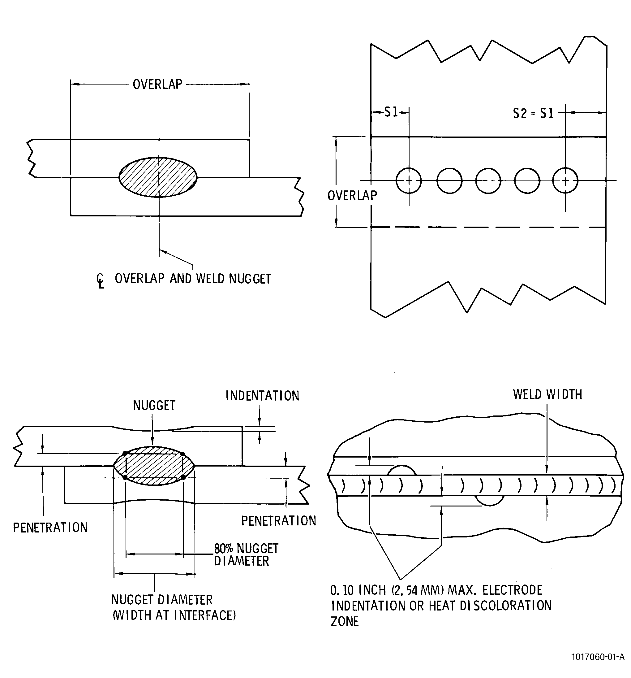
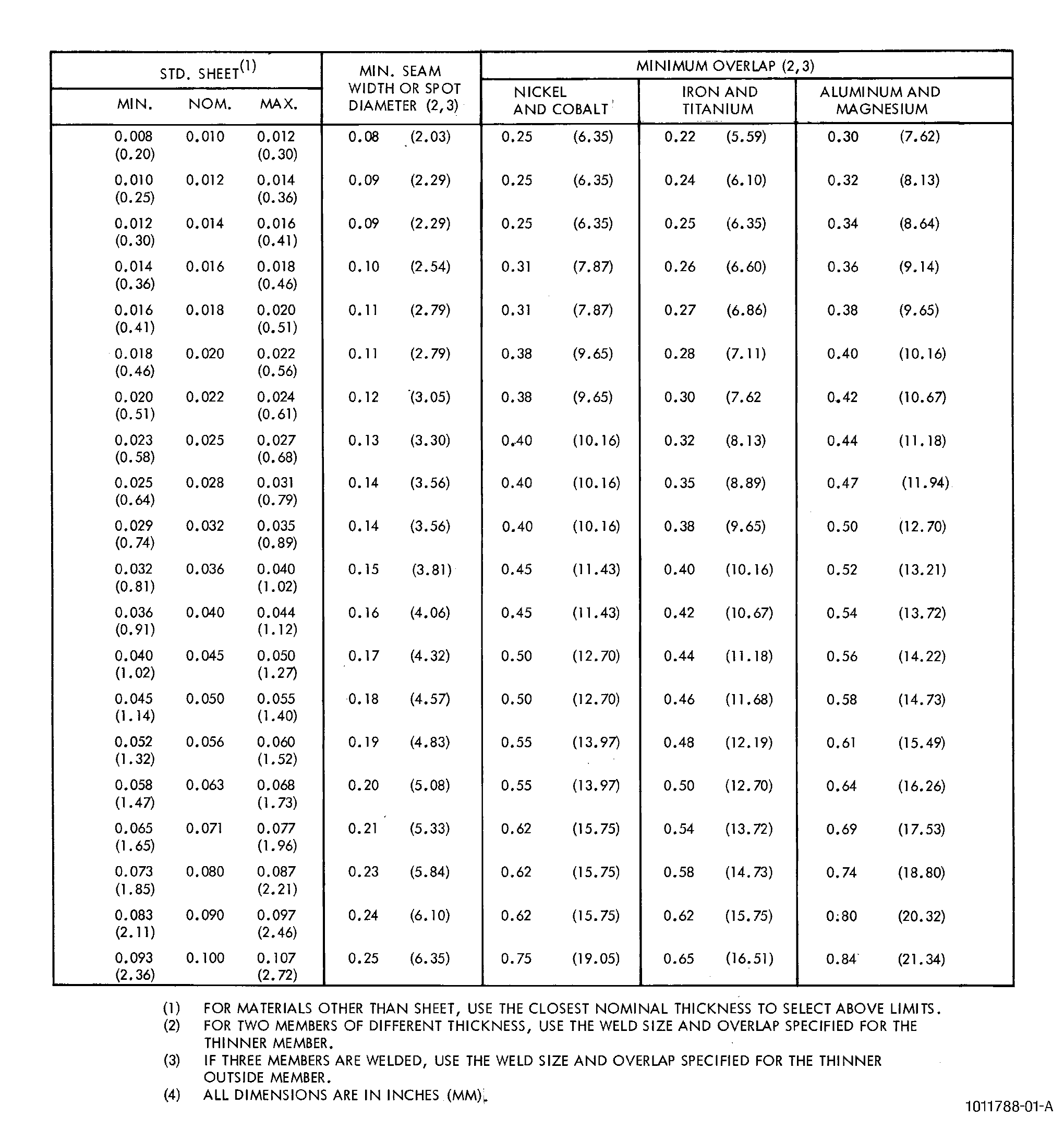
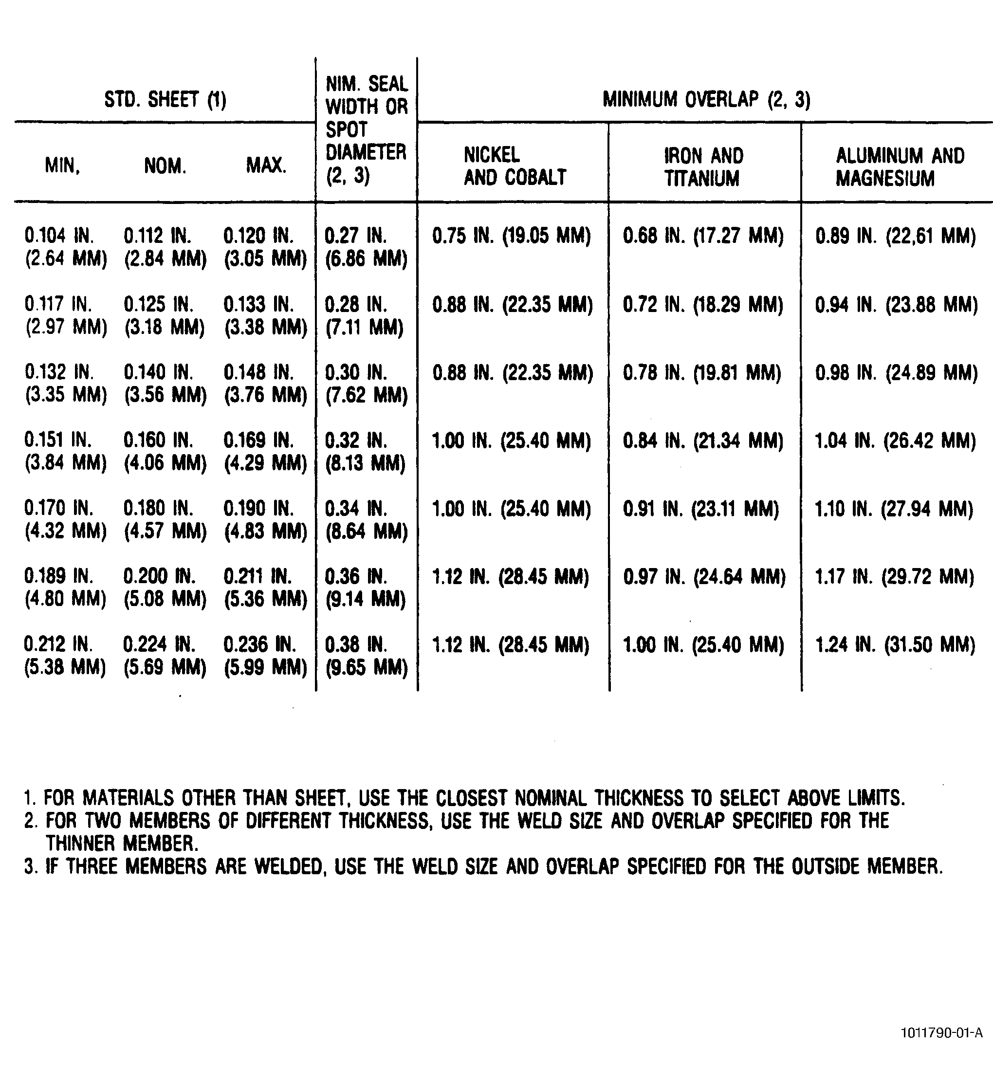
| A. | In lieu of the specific Engine/Shop Manual repair instructions, the centerline for spot or seam welds should be the centerline of the contacting overlap (see Figure 1). Any displacement with respect to the centerline should not exceed one-half the spot diameter (or seam width) or 0.10 inch (2.5 mm), whichever is greater. The recommended minimum overlap is given in Figure 2 for common sheet sizes. |
| B. | When spot tack welds are used for temporary assembly or fitup prior to a permanent joining process such as brazing or resistance welding, the tack welds must be in alignment with the permanent joint spot welds within one-half the spot diameter or 0.10 inch (2.5 mm), whichever is greater. Assembly spot tack welds for seam welding must be in alignment with the permanent seam weld so that no indented or discolored surface extends more than 0.10 inch (2.5 mm) beyond its outer edge. Refer to Figure 1. Actual spot tack welds should be located so as to be contained within the permanent overlap spot or overlapping linear seam welds. Tack welds require no test specimens and shall be of sufficient strength to fulfill their temporary function, and are not subject to other requirements except that external indications shall not exceed any limits specified in the process document. |
| C. | Minimum penetration (see Figure 1) into all sheets must not be less than 20 percent of the measured original thickness of the thinner outer sheet, over an area whose major axis is 80 percent of the weld diameter or width at the interface. Maximum penetration into either outer sheet must not be greater than 80 percent of its reduced thickness for aluminum and magnesium alloys, and 90 percent of its reduced thickness for all other alloys. Indentations should not exceed 10 percent of the measured original sheet thickness or 0.005 inch (0.13 mm), whichever is greater. |
| 6 . | Quality Assurance. |
| Subtask 70-41-04-310-055 |
| A. | Unless otherwise specified by the Engine/Shop Manual repair, resistance welds should meet the following quality standards. |
| (1) | Cracks and Indications. |
| (a) | Outer surfaces of welds shall be free from cracks. |
| (b) | Internal indications within spot and seam weld nuggets which do not extend more than one-third of the depth of penetration of the nugget from the faying plane toward the outer sheet, in a direction perpendicular to the interface, shall be acceptable. |
| (c) | Internal indications within spot weld nuggets, measured in a direction parallel to the interface, which do not exceed one-quarter of the nugget diameter in length, shall be acceptable. |
| (d) | Internal indications within seam weld nuggets, measured in a direction parallel to the interface, which do not exceed one-third of the nugget width as shown by a cross section, or one-third of the nugget spacing as shown by a longitudinal section, shall be acceptable. |
| (2) | Inspection Methods. |
| Inspection of resistance welded parts coupons shall be by welding, cutting, polishing, etching, peel or tensile testing, and evaluating specimens to determine conformance to applicable requirements. |
| (a) | All coupons for welding test specimens shall be prepared from the same material, including heat treatment condition, thickness, surface finish and surface preparation, and by the same procedure used for preparation of parts to be welded. Specimens with a radius are required if the radius of curvature is less than10 inches (254 mm). Sheet stock may be used for making coupons when the part is cast or machined, provided the surface finishes, resistances, and weld results are comparable. Coupons for aluminum and aluminum alloys should accompany parts through cleaning operations, and simulate cleaning methods and time limits placed on parts being welded. Specimens shall be welded with the overlap the same as the part weld. |
| (b) | A minimum of 3 specimen welds should be prepared and evaluated, after a machine is setup for a specific weld operation, prior to making part weld, and upon completion of weld. |
| (c) | Test specimens as follows: |
| 1 | Etch test. |
| Two specimens are to be prepared by polishing and etching a cross section of the weld through the center of a spot weld, or perpendicular to the direction of welding of a seam weld, and perpendicular to the weld interface. |
| 2 | Peel test. |
| One specimen is to be mechanically peeled apart with the resulting destruction of the parent material around the weld, or the weld itself. In seam weld specimens, peel from finishing end, not beginning of specimen weld. The size of the weld is measured at the faying surface and is the diameter or width of the "button" or of the fractured metal, if failure occurs along the faying surface. |
| (d) | Spot diameter or seam weld width or indication size are measured to the nearest 0.01 inch (0.3 mm). Indentation and base metal thickness shall be measured to the nearest 0.002 inch(0.05 mm). Penetration shall be measured to the nearest 0.002 inch(0.05 mm), or accuracy of measurement shall be such as to preclude acceptance of welds having penetration under minimum. |
| (e) | Projection welds are inspected by peel testing. Etch testing is not required. The strength value for each projection weld should exhibit a tensile shear strength of 50 pounds (222 N) minimum, unless otherwise directed by a specific Engine/Shop Manual repair. |
| (f) | Weldments are acceptable if all specimen welds evaluated meet the requirements in paragraph 5.C. and Figure 2, or the specific requirements of the Engine/Shop Manual repair. See the requirements in paragraph 5.C. of Subtask 70-41-04-310-054, Resistance Spot and Seam Weld Geometry and Requirements. |
| 7 . | Weld Rework. |
| Subtask 70-41-04-310-056 |
| A. | Rework of defects will be by TIG welding to the specific requirements of the Engine/Shop Manual repair. |