| COMMERCIAL ENGINE STANDARD PRACTICES MANUAL | Dated: 07/25/2022 | |
| SPM 70-48-22 REPLACEMENT OF RING-LOCK INSERT | ||
| COMMERCIAL ENGINE STANDARD PRACTICES MANUAL | Dated: 07/25/2022 | |
| SPM 70-48-22 REPLACEMENT OF RING-LOCK INSERT | ||
| TASK 70-48-22-350-801 |
| 1 . | General. |
| A. | This repair provides the instructions for the removal and replacement of ring-locked inserts. |
| 2 . | Tools and Equipment. |
| Subtask 70-48-22-350-001 |
| • |
|
| • |
|
| • |
|
| • |
|
| • |
|
| • |
|
| • |
|
| • |
|
| • |
|
| • |
|
| • |
|
| • |
|
| • |
|
| • |
|
| • |
|
| • |
|
| • |
|
| • |
|
| • |
|
| 3 . | Consumable Materials. |
| Subtask 70-48-22-350-002 |
| NOTE: |
|
|
| 4 . | Procedure. |
| Subtask 70-48-22-350-003 |
| A. | Procedure for removal of the ring-locked insert. |
| NOTE: |
|
| (1) | If necessary, clean the work area prior to attempt any repairs to prevent contamination of the assembly. |
| (2) | Remove the non-serviceable threaded insert and ring-lock from the assembly. Refer to Figure 1, Figure 4, Figure 6, and as follows: |
| (a) | Use a plug or tape C10-189 or C10-021 to seal the openings around the repair area in the assembly to prevent contamination or other means to protect the assembly from contamination. Use tape C10-021 or C10-189 to cover the inner side of the bolt holes repaired on the engine case to prevent debris that fall through the bolt holes. |
| WARNING: |
|
| CAUTION: |
|
| CAUTION: |
|
| (b) | With the correct use of the size drill bit with stop collar, set the collar to a drill depth of 0.090 inch (2.28 mm), align the drill bit with the center-line of the damaged insert, and drill into the insert. |
| (c) | Use a vacuum during the drilling procedures to reduce the possibility that metal particles contaminates the assembly. |
| (d) | Use a punch to assist the removal of the ring-lock as follows: |
| 1 | Put the punch on one end of the ring-lock and use a hammer to tap the punch lightly. |
| 2 | Carefully, lift the ring-lock from the oval shaped counterbore hole. |
| (e) | Use the correctly sized allen key or locally manufactured installation drive tool to remove the damaged insert. |
| 1 | The damaged insert cannot be used again and should be discarded. |
| (f) | Remove all the unwanted material from the assembly repair area. |
| (3) | Do a visual inspection of the threads in the assembly repair area. Refer to Figure 6 and as follows: |
| (a) | If necessary, remove the high metal from the threaded hole with a tap to chase the threads. |
| (b) | Use clean compressed air to remove the loose metal chips from the tapped hole. |
| (c) | If more than the first thread remains damaged after to chase the threads, this part cannot be repaired by this procedure. |
| (4) | Blend the counterbore and countersink by hand to remove the high metal. Refer to TASK 70-42-00-350-002 (70-42-00, Blending and Removal of High Metal Procedures). |
| NOTE: |
|
| WARNING: |
|
| (5) | Use clean compressed air to remove the loose metal chips from the tapped hole. |
| (6) | If required, clean the counterbore. |
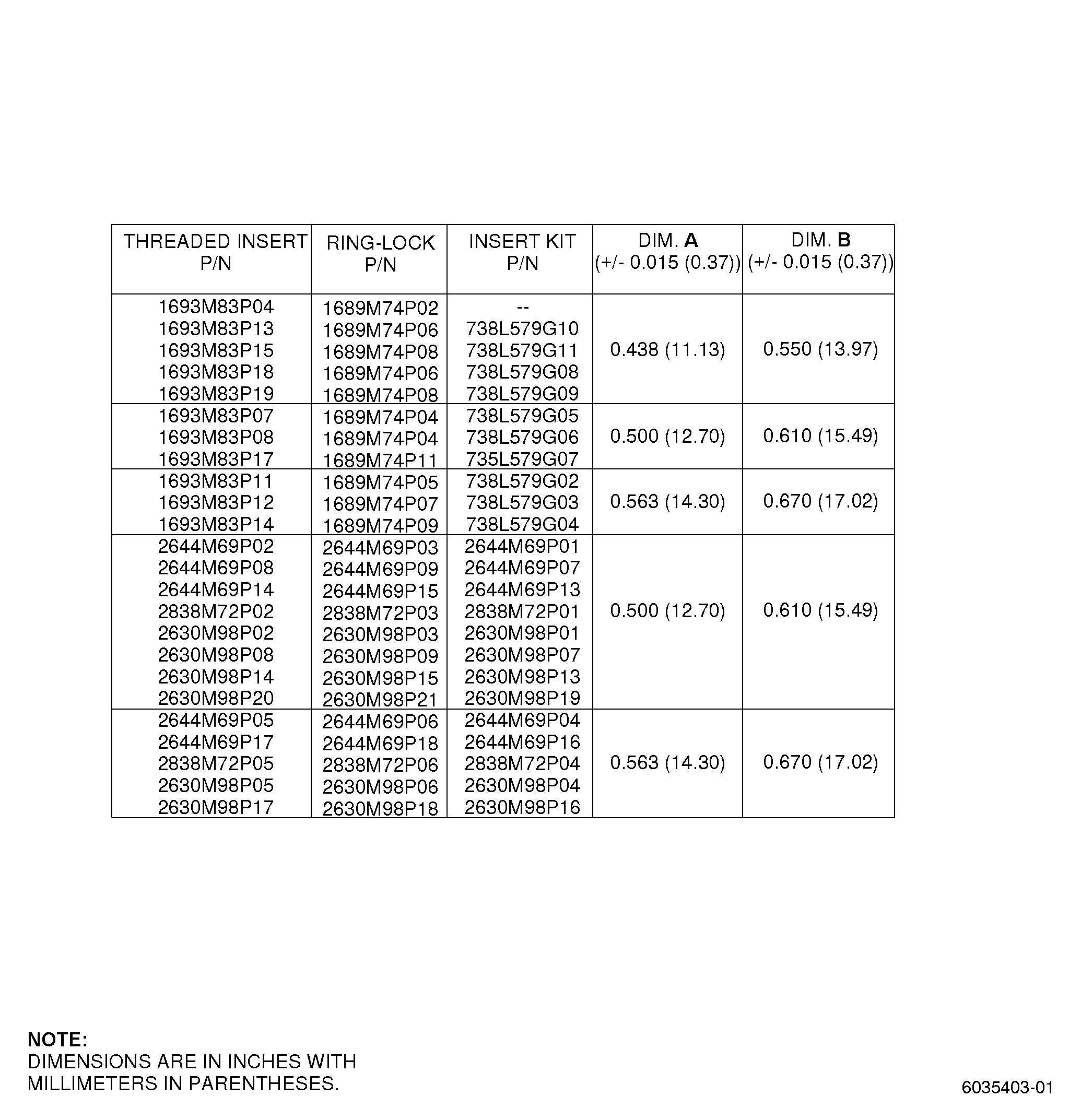
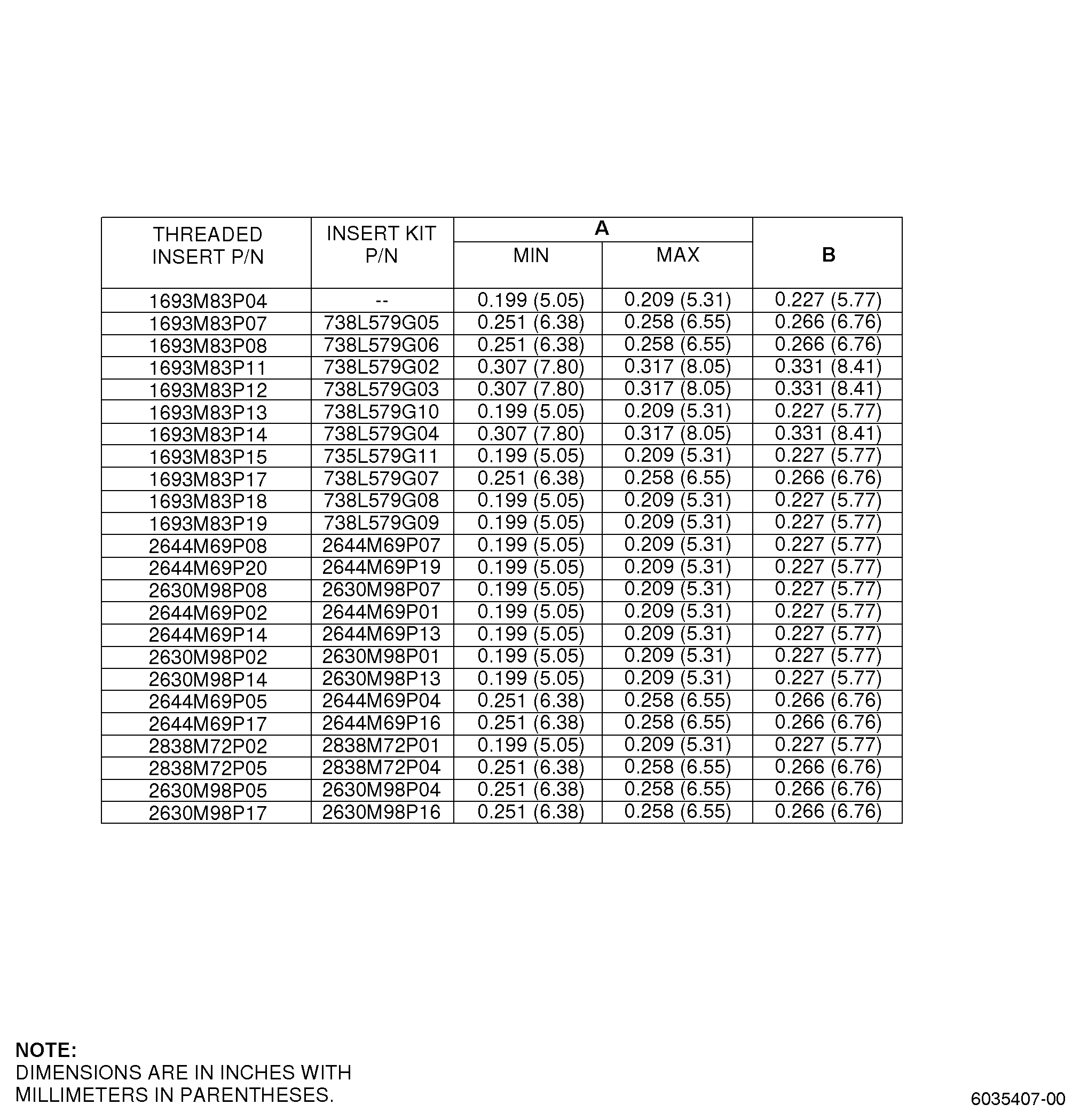
| (7) | Do a dimensional inspection of the counterbore. Refer to Figure 2 and as follows: |
| (a) | If the dimensions do not agree with the limits, you cannot repair the assembly with this procedure. |
| (8) | Do an inspection of the threads in the hole that is repaired as follows: |
| (a) | If the threads are not serviceable, you cannot repair the assembly with this procedure. |
| B. | Procedure for the Installation of the Ring-Lock Insert |
| NOTE: |
|
| (1) | Install the new insert and the new ring-lock in the assembly. Refer to Figure 2, Figure 3, Figure 4, and as follows: |
| (a) | Make sure that you remove all the unwanted material from the threaded hole and the counterbore before you install the new threaded insert and the ring-lock. |
| (b) | Use the same size insert as the damaged threaded insert that you removed. |
| (c) | Install the new threaded insert into the threaded hole of the assembly as follows: |
| 1 | If the assembly is not aluminum, apply engine lubricating oil C02-019 or C02-023 to the insert OD as necessary to assist with insert installation. |
| 2 | If the assembly is aluminum, wet install the insert and ring-lock as follows: |
| a | Apply paint C03-100 on the shanks, threads, and bearing surface of the insert and ring-lock. |
| 3 | Put the insert into the threaded hole with the correctly sized allen key wrench or locally manufactured installation drive tool and as follows: |
| a | Install the insert in the case until the top face of the insert is 0.010-0.030 inch (0.25-0.76 mm) below the assembly surface. |
| (2) | Install the new ring-lock on the threaded insert and into the oval shaped hole of the assembly. Refer to Figure 3 and as follows: |
| (a) | The word TOP on the ring-lock must face out from the assembly. |
| (b) | Align the serrations on the threaded insert with the serrations of the ring-lock. |
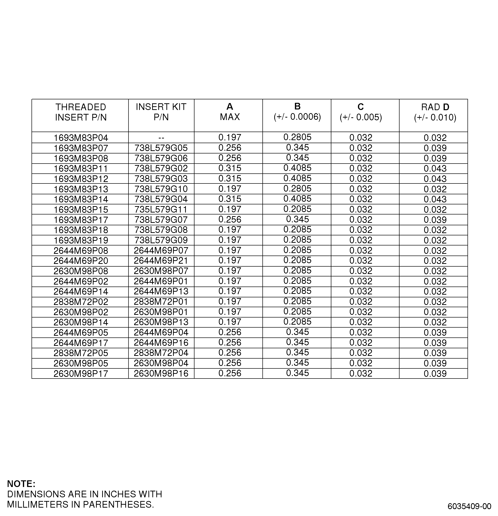
| (3) | Swage the new threaded insert into the ring-lock. Refer to Figure 3, Figure 5, and as follows: |
| (a) | Make a swage tool to meet the dimension requirements. |
| (b) | Put the swage tool into the screw insert and the ring-lock. |
| (c) | Push the ring-lock to make contact with the bottom of the counterbore. |
| (d) | Use a hammer to tap the swage tool until the nylon stop washer of the swage tool touches the pad on the assembly. |
| (4) | Remove the swage tool. |
| (5) | Do an inspection of the insert and ring-lock. Refer to Figure 3 and as follows: |
| (a) | Use 10X magnification. |
| (b) | Make sure that the insert serrations are swaged into the serrations of the ring-lock. |
| (c) | Make sure that the ring-lock is a minimum of 0.002 inch (0.05 mm) below the assembly surface. |
| (d) | Use a pointed pick to try to lift the ring-lock with light hand pressure on the pick and make sure that the ring-lock does not lift out of the counterbore. |
| CAUTION: |
|
| (6) | In case you use the self-locking ring lock insert, do a check of the self-locking torque of the threaded insert. Refer to Figure 7 and as follows: |
| (a) | Install the correct size bolt and washer into the replaced ring-locked self-locking insert. |
| NOTE: |
|
| (b) | Use a torque wrench to torque the installed bolt in the torque range and as follows: |
| 1 | The lock-ring can rotate in the counter bore if the torque range is met. |
| NOTE: |
|
| (c) | Remove the bolt and flat washer from the threaded insert. |
| CAUTION: |
|
| (7) | Remove any masking tape, plugs, or other means that were used to keep contaminates from the entering assembly. |