| COMMERCIAL ENGINE STANDARD PRACTICES MANUAL | Dated: 10/03/2023 | |
| SPM 70-51-00 TIGHTENING PRACTICES AND TORQUE VALUES | ||
| COMMERCIAL ENGINE STANDARD PRACTICES MANUAL | Dated: 10/03/2023 | |
| SPM 70-51-00 TIGHTENING PRACTICES AND TORQUE VALUES | ||
| TASK 70-51-00-400-004 |
| 1 . | General. |
| A. | This standard practice details the methods, terms, and procedures used in tightening and applying torque to threaded fasteners such as, bolts, nuts, and fittings. |
| B. | Torque in pound-inches (lb in.) or newton-meters (N·m), is the specific twisting force applied to threaded fasteners to obtain optimum security of the part, within the tensile limits of the material, or the shear limits of the threads of the fastener. One lb in. (N·m) is the twisting force of one pound (0.45 kg) applied to a lever one inch (25.4 mm) long. Higher torque values are equal to the product of the pounds (kilograms) times the length of the lever in inches (millimeters). |
| NOTE: |
|
| 2 . | Definition of Terms. |
| Subtask 70-51-00-400-041 |
| A. | Bolt. |
| For purposes of these definitions, any male-threaded part. |
| B. | Breakaway Torque. |
| The torque required to just start an installed nut moving off the bolt, with no axial load on the bolt. (Nut is not seated, but is stationary at initiation of torque.) |
| C. | Gross Torque. |
| The actual indicated torque applied by the torque wrench, including run-on torque and seating torque. |
| D. | Installed Nut. |
| A nut is defined as installed on a bolt when not less than chamfer plus one and a half threads of the bolt extend beyond the nut. Nuts that have midlength nylon inserts or other centralized locking devices do not require the bolt to protrude from the nut, as long as the bolt passes through the locking device by the chamfer plus one and a half threads. |
| E. | Maximum Installation Torque. |
| The highest value obtained as the nut is initially installed, and is being sized (opened up or worn in) by the bolt. |
| F. | Minimum Prevailing Torque. |
| The minimum value obtained while the nut or bolt is in motion from the end of the first revolution to the end of the second revolution during the removal of the nut from the bolt, or the bolt from a threaded hole. |
| G. | Removed Nut. |
| A self-locking nut is defined as removed when the locking section is disengaged from the bolt. (The nut need not be physically removed from the bolt.) |
| H. | Run-On Torque. |
| The torque required to turn a nut or bolt before it is completely seated to perform an axial tightening action on the bolt or spacing elements. |
| I. | Seated Nut/Bolt. |
| The torque that applies a specified compressive force to the spacing elements, or an axial loading or elongating force to a bolt, after the bearing surfaces of the bolt and/or nut are in contact with the spacing elements. |
| J. | Spacer, Spacing Elements. |
| For purposes of these definitions, any parts, regardless of function, size, shape, or material that are held together by one or more threaded fasteners. |
| K. | Unseated Nut/Bolt. |
| A nut or bolt is defined as unseated when it is removed a minimum of one turn from the seated position, removing any axial load from the bolt. |
| L. | Unseated Torque. |
| The torque required to unseat the bearing surface of a nut or bolt from a spacer, removing all axial load from the bolt. |
| 3 . | Tightening Procedure. |
| Subtask 70-51-00-400-042 |
| CAUTION: |
|
| A. | Tighten at a uniform rate until the specified torque is obtained. In some cases, where gaskets or other parts cause a slow permanent set, be sure to check the torque at the desired value after the material is seated. |
| B. | Do not tighten to the final torque value during the first drawdown; uneven tension can cause distortion or overstressing of parts. Seat mating parts by drawing down the bolts in gradual increments, following a staggered or diametrically opposite sequence, until the parts are firmly seated. Complete the tightening procedure by loosening each fastener separately, then tighten to the specified torque value. Do not exceed the maximum torque values specified by the engine manual. |
| 4 . | Torque Wrench Sizes. |
| Subtask 70-51-00-400-043 |
| A. | This standard practice does not cover the use of torque multipliers to obtain higher torque values. Information regarding the operation of such equipment can be found in the manufacturer's literature. |
| B. | The torque wrenches listed below are recommended for use within the indicated ranges. Torque wrenches should be capable of maintaining accuracies to within ± 5 percent of the specified torque value. The smaller of the tolerance values referenced in the table below is the required torque wrench accuracy limit for the specified torque. Larger wrenches have a wider tolerance, and their use can result in serious inaccuracies. |
| 5 . | Use of Offset Extension Wrench. |
| Subtask 70-51-00-400-044 |
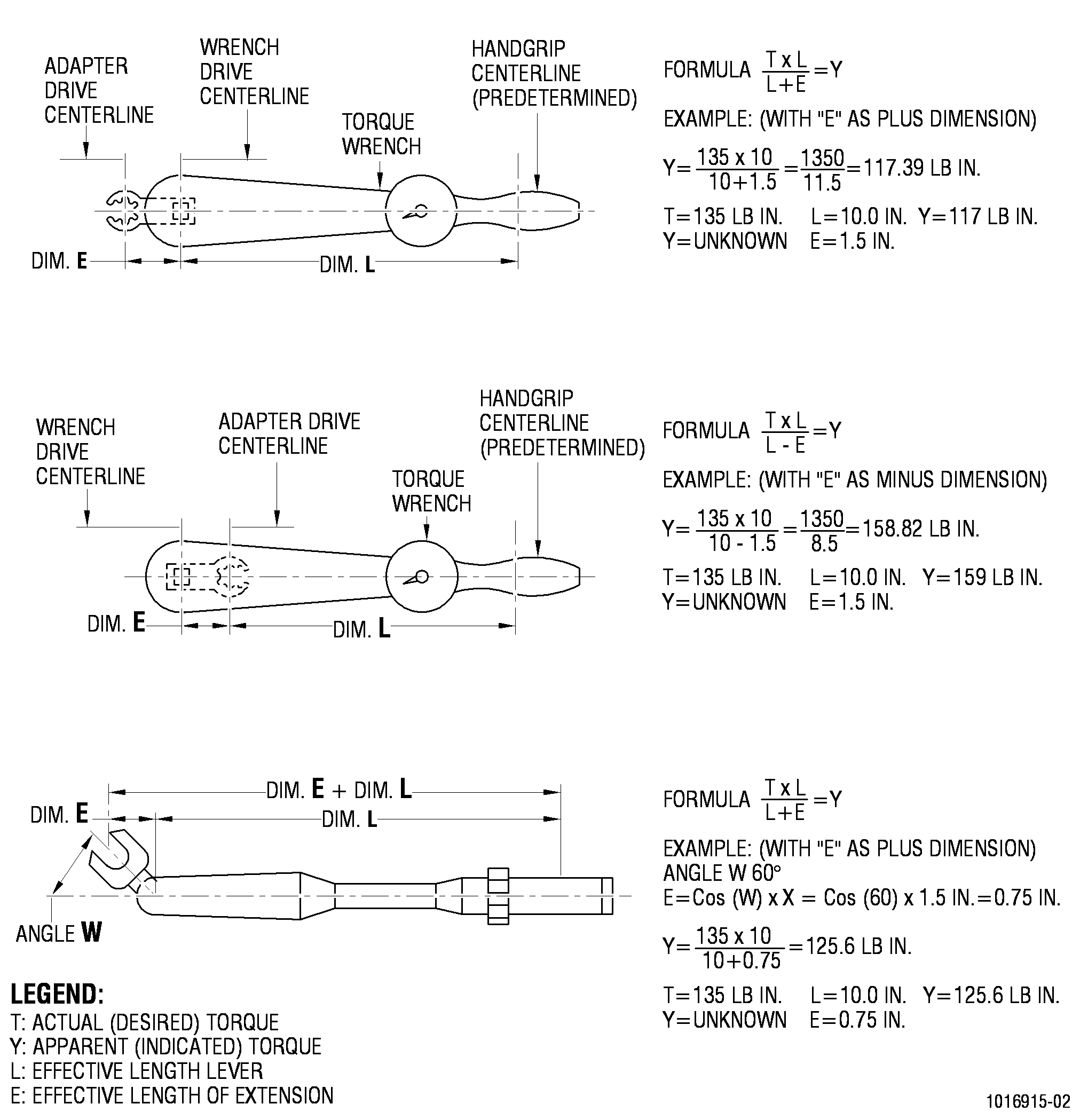
| A. | When an offset extension wrench, such as a crowfoot extension, is used with a torque wrench, the effective length of the torque wrench is changed. The torque wrench is so calibrated that when an extension wrench is used, the indicated torque, the value that appears on the scale or dial of the torque wrench, may be different from the actual torque that is applied to the nut or bolt. See Figure 1. |
| B. | The Method of Computing the Adjustment is as follows: |
| (1) | The addition or subtraction of the effective length of the crowfoot extension (E) is determined by its position on the torque wrench (L). When the extension wrench is pointed in the same direction as the torque wrench, add the effective length of the extension to the effective length of the torque wrench (L + E). When the extension is pointed back toward the handle of the torque wrench, subtract the effective length of the torque wrench (L - E). The effective length of the extension is calculated by multiplying the Cos (W) by the actual length of extension. Angle W is defined as the angle extension wrench and torque wrench. When the extension is pointed in the same angle as the torque wrench, then the effective length of the extension is equal to the actual length of the extension. When the extension is pointed at right angles to the torque wrench, the effective length does not change. The effective length (L) of the torque wrench is predetermined by the torque wrench manufacturer. Refer to manufacturer's specification for the particular torque wrench being used. The effective length (E) of the crowfoot extension is determined by measuring from the center of the drive opening to the center of the wrench opening. |
| (2) | Multiply the required torque (T) by the effective length of the torque wrench (L). Divide this product by (L + E) or (L - E) as determined from Figure 1. The quotient is the gage or scale reading required to obtain the desired torque. |
| For example: Required torque = 265 lb in. (29.94 N·m) Effective length of torque wrench = 8.4 inches (213.36 mm) Effective length of crowfoot = 1.5 inches (38.1 mm) |
| Then: (Required torque) X (L) = 265 X 8.4 = 2226.0 (29.94 N·m X 213.36 mm = 6388.00) |
| (L + E) = 9.9 inches (251.46 mm) |
| 2226.0 divided by 9.9 = 224.85 lb in. |
| 6388.00 divided by 251.46 = 25.404 N·m |
| Thus: A gage reading of 225 lb in. indicates a required torque of 265 lb in. (A gage reading of 25.42 N·m indicates a required torque of 29.94 N·m) |
| 6 . | Standard Torque Values. |
| Subtask 70-51-00-400-045 |
| A. |
|
|||||||||||||||||||||||||||||||||||||||||||||||||||||||||||||||||||||||||||||||||||||||||||||||||||||||||||||||||||||||||||||||||||||||||||||||||||||||||||||||||||||||||||||||||||||||||||||||||||||||||||||||||||||||||||||||||||||||||||||||||||||||||||||||||||||||||||||||||||||||||||||||||||||||||||||||||||||||||||||||||||||||||||||||||||||||||||||||||||||||||||||||||||||||||||||||||||||||||||||||||||||||||||||||||||||||||||||||||||||||||||||||||||||||||||||||||||||||||||||||||||||||||||||||||||||||||||||||||||||||||||||||||||||||||||||||||
|
|||||||||||||||||||||||||||||||||||||||||||||||||||||||||||||||||||||||||||||||||||||
|
|||||||||||||||||||||||||||||||||||||||||||||||||||||||||||||||||||||||||||||||||||||||||||||||||||||||||||||||||||||||||||||||||||||||||||||||||||||||||||||||||||||||||||||||||||||||||||||||||||||||||||||||||||||||||||||||||||||||||||||||||||||||||||||||||||||||||||||||||||||||||||||||||||||||||||||||||||
|
||||||||||||||||||||||||||||||||||||||||||||||||||||||||||||||||||||||||||||||||||||||||||||||||||||||||||||||||||||||||||||||||||||||||||||||||||||||||||||||||||||||||||||||||||||||||||||||||||||||||||||||||||||||||||||||||||||||||||||||||||||||
| 7 . | Tightening of Plugs and Tube Fittings. |
| Subtask 70-51-00-400-046 |
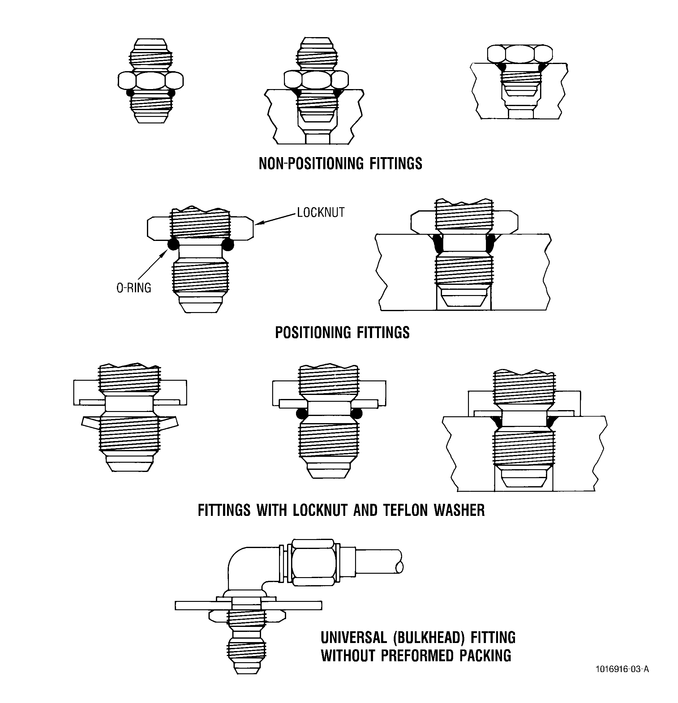
| A. | Assembly techniques vary, depending upon the specific type of plug or tube fitting being used. The types normally encountered include nonpositioning plugs and unions, using packings preformed (O-rings) or other compressible packing for seals; positioning fittings, with or without backup washers; and universal bulkhead fittings, held in position by locknuts. See Figure 2. |
| B. | All tube fittings should be tightened to their proper torque using two wrenches. The secondary wrench is used to apply counter-torque to prevent distortion of the tubing assembly. |
| C. | Correct Assembly Techniques. |
| CAUTION: |
|
| CAUTION: |
|
| CAUTION: |
|
| (1) | Installation of Packings Preformed (O-Rings) on Fittings. |
| (a) | When ratio of packing preformed (O-ring) diameter to cross-section is greater than 20, use a conic sleeve screwed onto fitting so that packing preformed (O-ring) may be rolled into groove of fitting without danger of being damaged. |
| (b) | For diameter ratios less than 20, a conic sleeve is not needed, except when the packing preformed (O-ring) must be rolled over threads or splines. |
| (c) | Lubricate packing preformed (O-ring) with C02-033 soft petrolatum, C02-008 petroleum jelly, C02-021 grade 1010 oil, C02-091 grade 1005 oil, or C02-019 engine lubrication oil or C02-023 engine lubrication oil, and roll it into groove of fitting. |
| (d) | If the preformed packing (O-ring) requires a tacky type assembly fluid to perform the function of retaining the preformed packing in the seal groove, use C02-007 assembly fluid or C02-090 O-ring lubricant to minimize the risk of damage during assembly. |
| (2) | Lubrication. |
| Use no lubricant on threads or friction surfaces unless specified by the engine manual. |
| (3) | Nonpositioning Fittings. |
| Lubricate the packing lightly to prevent cutting by sharp threads, then install packing on fitting so that packing lies evenly in groove of fitting. Screw fitting into boss. Tighten to the specified torque value. |
| (4) | Positioning Fittings (No Backup Washers). |
| Screw the locknut completely over the first section of threads on the fitting, past the packing groove, and onto the second section of threads. Lubricate packing to prevent cutting by sharp threads, and install it carefully over first section of threads and into the packing groove so that it lies evenly against the second section of threads. Turn locknut until it just bears against the packing. Install fitting in boss so that packing touches the countersunk surface. Turn fitting to desired position by backing out (counter clockwise rotation) not more than one turn. Hold fitting in position and tighten locknut to the specified torque value. |
| (5) | Positioning Fittings (With Backup Washers). |
| Screw the locknut completely over the first section of threads on the fitting, and onto the second section of threads with the washer recess facing the packing groove. Grip the backup washer firmly by its outside edge, and screw the fitting into the cupped washer. Do not use any lubricant. Continue screwing the washer onto the fitting until the washer is free on the packing groove. Pick out any slivers of plastic material cut from the washer, then press the edges of the washer into the recess in the locknut until evenly seated. Ensure that threads of fitting do not interfere with seating of washer. Lubricate and install packing as directed in step (3). Hold the locknut in position with a wrench, and turn the fitting into the boss 1.5 turns. Position the fitting as desired by turning into the boss up one additional turn (total 1.5-2.5 turns). Hold fitting in position, and tighten locknut to the specified torque value. |
| (6) | Universal Bulkhead Fittings. |
| Attach bulkhead fitting to bulkhead with locknut as shown in Figure 2. After the connecting tube or hose nut has been properly tightened, hold fitting with wrench and tighten locknut to the specified torque value. |
| (7) | Tube, Manifold, and Hose coupling nuts triple tightening procedure. |
| (a) | Tighten the coupling nut to applicable torque identified in Subtask 70-51-00-400-045, Standard Torque Values. |
| (b) | Break the torque on the coupling nut and then tighten to the torque value identified above. |
| (c) | Check joint by tightening the coupling nut again to the torque value identified above. |
| 8 . | Net Torque. |
| Subtask 70-51-00-400-047 |
| A. | In certain applications, engine manuals may specify a net torque value when the tightening force applied by the fastener is critical, and must be controlled within precise limits to obtain a specific amount of stretch to a bolt or to provide an exact amount of hold-down pressure. |
| B. | Net torque equals gross torque minus run-on torque. The method of determining net torque is shown in the following example. |
| (1) | Requirement to tighten a nut on a bolt to a net torque of 20-40 lb in. (2.46-4.52 N·m). |
| (2) | Screw the nut on the bolt, and determine the torque required to turn the nut before any tightening action takes place. Record this value as run-on torque. Assume the value to be 15 lb in. (1.69 N·m). |
| (3) | Add the run-on torque value determined in step (2) to the minimum and maximum specified torque values. |
| Then: 20 lb in. (2.26 N·m) plus 15 lb in. (+1.69 N·m) equals 35 lb in. (3.95 N·m), and40 lb in. (4.52 N·m) plus 15 lb in. (+1.69 N·m)equals 55 lb in. (6.21 N·m). |
| Therefore: to obtain a net torque of 20-40 lb in. (2.26-4.52 N·m), a gross torque of 35-55 lb in. (3.95-6.21 N·m) must be applied to the nut. |
| 9 . | Torque Check for Re-Use of Self-Locking Nuts. |
| NOTE: |
|
| Subtask 70-51-00-400-048 |
| A. | Self-locking nuts must meet the minimum breakaway torque requirements to be considered reusable. |
| B. | The requirements for this torque check are as follows. |
| (1) | Refer to the following list for minimum breakaway torque on self-locking nuts. This list applies to both silver-plated and dry-film coated self-locking nuts, with or without lubrication. Values given are for nuts with no axial load. |
| NOTE: |
|
| (2) | To check minimum breakaway torque, install the nut onto a bolt until 2 to 5 threads are exposed beyond the nut. Measure the amount of torque required to turn the nut on or off the bolt. |
| CAUTION: |
|
| (3) | All nuts that do not meet these minimum frictional requirements should be replaced. |
| Minimum Breakaway Torque for Self-Locking Nuts |
|
| 10 . | Torque Procedure for V-Band Type Clamps. |
| Subtask 70-51-00-400-049 |
| A. | Refer to TASK 70-10-02-800-801,V-Coupling Assembly Techniques. |
| NOTE: |
|
| 11 . | Torque Procedure for Misalignment Joint Couplings. |
| Subtask 70-51-00-400-050 |
| A. | Lubricate threads with antiseize compound C02-058 . |
| B. | Tighten the misalignment joint coupling nut to 50 percent of the required torque. Make certain that the female fitting is seated and centered over the male fitting equally around the periphery, and make certain the metal gasket seal is properly seated. |
| C. | With plastic or non-metallic mallet, tap the coupling nut lightly around its circumference to distribute the misalignment joint loading. |
| D. | While increasing the torque toward 100 percent of the specified value, lightly tap the outer periphery, as necessary, to prevent unequal loading. |
| E. | After 100 percent of the specified torque is reached, tap around the coupling nut outer periphery again. |
| F. | Break torque and loosen coupling nut of the misalignment fitting one-half turn. |
| G. | Tighten once more to the specified torque value. |
| H. | Assemble shields to joints, as applicable. |
| 12 . | Acceptability Limits, Acceptance Torques. |
| Subtask 70-51-00-400-051 |
| A. | This procedure describes the verification that torque values specified on a drawing or in a specification have been met. |
| B. | For the purposes of this specification, the following definitions apply: |
| (1) | Acceptance Torque - The torque applicable after final assembly. It shall include the net effect of the torque required to overcome friction between mating bearing faces and between mating threads, to overcome the self-locking feature (if any) and, to apply the desired axial load to the fastener assembly. It also includes the effect of joint/fastener relaxation. The acceptance torque shall be measured only in the tightening direction with the mating fastener component restrained. |
| (2) | Seating Torque - The torque required by drawing or specification to bring the bearing faces into the seated position and measured only in the tightening direction. |
| C. | Requirements. |
| (1) | Application - The conditions described herein shall be applied only to parts which have been assembled into a sub-assembly or an engine prior to engine test. |
| (2) | Acceptance Torque Requirements - The acceptance torque requirements for self locking nuts shall be in accordance with the following table. You must know the bolt size (column 1) and the seating torque value (column 2) in order to derive the acceptance torque (column 3). The acceptance torques shall be measured in the tightening direction. These values shall be used in the process of inspecting or auditing to insure that the proper seating torque has been applied. |
|