| GENX-1B CLEANING,INSPECTION,AND REPAIR MANUAL | Dated: 12/06/2024 | |
| CIR 72-00-00 , INSPECTION 003 | ||
| ENGINE ASSEMBLY - INSPECTION GUIDELINES FOR ACCESSORIES AND LINE REPLACEABLE UNITS | ||
| GENX-1B CLEANING,INSPECTION,AND REPAIR MANUAL | Dated: 12/06/2024 | |
| CIR 72-00-00 , INSPECTION 003 | ||
| ENGINE ASSEMBLY - INSPECTION GUIDELINES FOR ACCESSORIES AND LINE REPLACEABLE UNITS | ||
| * * * FOR ALL |
| TASK 72-00-00-200-807 |
| 1 . | General. |
| A. | This procedure gives detailed inspection guidelines for the engine accessories and line replaceable units (LRU). |
| 2 . | Tools, Equipment, and Materials. |
| NOTE: |
|
| A. | Tools and Equipment. |
| (1) | Special Tools. None. |
| (2) | Standard Tools and Equipment. None. |
| (3) | Locally Manufactured Tools. None. |
| B. | Consumable Materials. None. |
| C. | Referenced Procedures. |
| D. | Expendable Parts. None. |
| 3 . | Specific Inspection Guidelines for Engine Accessories and Line Replaceable Units (LRU). |
| Subtask 72-00-00-220-163 |
| A. | Do a general visual inspection (GVI) of the control and accessory components, either installed or removed for access. If defects are observed, refer to the inspection guidelines that follow or applicable Component Maintenance Manual (CMM) for serviceability limits. |
| NOTE: |
|
| Subtask 72-00-00-160-002 |
| (1) | If necessary, clean the part to do the GVI. Refer to TASK 70-20-00-100-001 (CLEANING ENGINE PARTS) and/or TASK 70-21-14-110-012 (CLEANING METHOD NO. 14 - MANUALLY-ASSISTED DETERGENT CLEANING). |
| Subtask 72-00-00-220-165 |
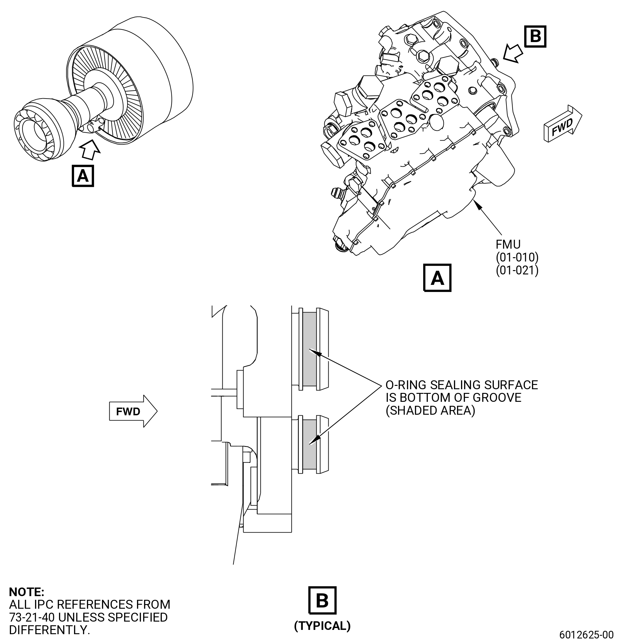
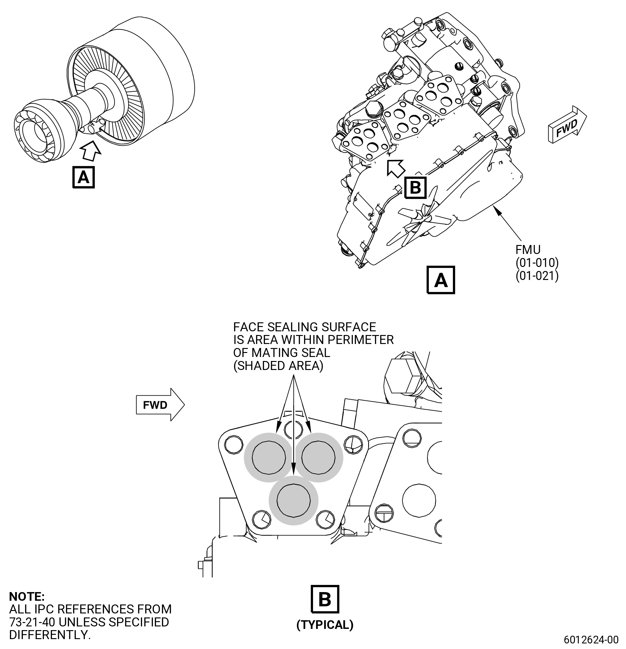
| (2) | Do an inspection for the fuel metering unit (FMU) as follows: |
| (a) | Do a visual inspection of the FMU (01-010 , 73-21-40) (SIN 30000) and (01-021 , 73-21-40) (SIN 30000) for: |
| 1 | Damage to machined or cast surfaces that are not sealing surfaces: |
| a | Do an inspection for cracks, dents, gouges, nicks, grooves or scratches. |
| b | Parts with defects that have raised material can be repaired by removing raised material. Refer to TASK 70-42-00-350-002 (BLENDING AND REMOVAL OF HIGH METAL PROCEDURES). If no repair is available, defects greater that 0.010 inch (0.25 mm) in depth or in height can be a cause for rejection. |
| c | Repair surface finish. Refer to TASK 70-43-07-380-007 (CHEMICAL TOUCH-UP SURFACE REFINISHING PROCESS FOR ALUMINUM). |
| 2 | Sealing surfaces are defined as those surfaces that are in contact with a mating seal (o-ring, packing, metal-to-metal). Examples are o-ring grooves, face seals, and AM fittings: |
| a | Do an inspection of the o-ring grooves for damage of the sealing surface. Refer to Figure 801. |
| b | Do an inspection of the face sealing surfaces within seal contact area for scratches or raised material. No defects are permitted. Refer to Figure 802. |
| NOTE: |
|
| c | Do an inspection of the AN type fittings. Examine the condition of the conical sealing surface. No defects are permitted in the center 60 percent conical seal surface. |
| NOTE: |
|
| 3 | Connector pins bent. |
| 4 | Connector threads damaged. |
| NOTE: |
|
| (b) | If the visual inspection check fails, replace the FMU. |
| Subtask 72-00-00-220-166 |
| (3) | Do a visual inspection of the flow split valve (FSVA) as follows: |
| (a) | Do a visual inspection of the FSVA (01-010A , 73-21-30) (SIN 31700) for: |
| 1 | Damage to machined or cast surfaces that are non-sealing surfaces: |
| a | Do an inspection for cracks, dents, gouges, nicks, grooves, or scratches. |
| b | Parts with defects that have raised material can be repaired by removing the raised material. Refer to TASK 70-42-00-350-002 (BLENDING AND REMOVAL OF HIGH METAL PROCEDURES). On machined or cast surfaces that are non-sealing surfaces, parts with defects more than 0.010 inch (0,25 mm) in depth or high can be a cause for rejection. |
| 2 | Damage to sealing surfaces. Sealing surfaces are defined as those surfaces that are in contact with a mating seal (o-ring, packing, metal-to-metal). |
| a | Do an inspection of the O-ring grooves for damage of the sealing surfaces. Refer to Figure 804. |
| b | Do an inspection of the sealing surfaces within seal contact area for scratches or raised material. |
| NOTE: |
|
| c | Examine the condition of the conical sealing surfaces on the AN type fittings. No defects are permitted in the center 60 percent conical seal surface. |
| NOTE: |
|
| Subtask 72-00-00-220-167 |
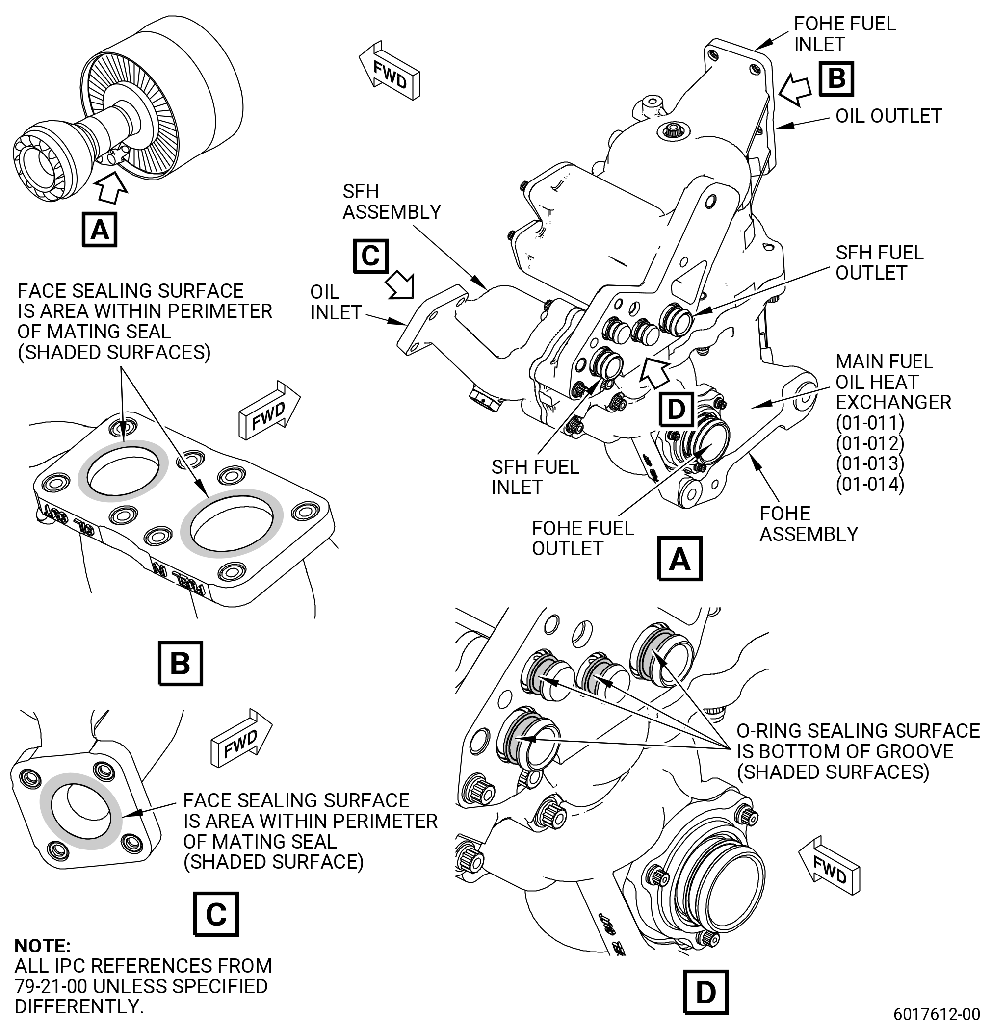
| (4) | Do a visual inspection of the main fuel oil heat exchanger (MFOHEx) as follows: |
| (a) | Do a visual inspection of the MFOHEx (01-011 , 79-21-00) (SIN 40700), (01-012 , 79-21-00) (SIN 40700), (01-013 , 79-21-00) (SIN 40700), and (01-014 , 79-21-00) (SIN 40700) for: |
| 1 | Damage to cases of MFOHEx. |
| a | Do an inspection for corrosion, cracks, and holes on flanges and mounts. Reject parts if any of these conditions are found. |
| b | Dents, marks, scores, and scratches on any non sealing surface. |
| c | Parts with defects that have raised material can be repaired by removing the raised material. Refer to TASK 70-42-00-350-002 (BLENDING AND REMOVAL OF HIGH METAL PROCEDURES). On machined or cast surfaces that are non-sealing surfaces, parts with defects more than 0.006 inch (0.152 mm) in depth or high can be a cause for rejection. |
| d | Defects located on the heat exchanger cases near by small radiuses, abrupt changes on geometry and greater than 0.006 inch (0.152 mm) are not acceptable. |
| 2 | Damage on transfer tubes. |
| a | Do an inspection on the transfer tubes. Reject the part if corrosion, scores, or scratches on the sealing surfaces (o-ring groves) are found. Refer to Figure 805. |
| b | Damage to the non-sealing surfaces up to 0.003 inch (0.076 mm) can be re-worked. Refer to TASK 70-42-00-350-002 (BLENDING AND REMOVAL OF HIGH METAL PROCEDURES). |
| Subtask 72-00-00-220-168 |
| (5) | Inspect the VSV actuator as follows: |
| (a) | Do a visual inspection of the VSV actuator (01-100 , 75-32-10) (SIN 30400) as follows: |
| 1 | Do a check for defects. Defects are specified as: |
| • |
|
| • |
|
| • |
|
| • |
|
| • |
|
| • |
|
| • |
|
| • |
|
| • |
|
| • |
|
| • |
|
| • |
|
| • |
|
| • |
|
| • |
|
| 2 | Return the actuator if one of the following conditions is found: |
| • |
|
| • |
|
| 3 | Return the part to the vendor if there is evidence of corrosion. |
| 4 | On machined or cast surfaces that are non-sealing surfaces, parts with defects more than 0.010 inch (0,25 mm) in depth or high can be a cause for rejection. |
| 5 | Parts with defects that have raised material can be repaired by removing the raised material. Refer to TASK 70-42-00-350-002 (BLENDING AND REMOVAL OF HIGH METAL PROCEDURES). |
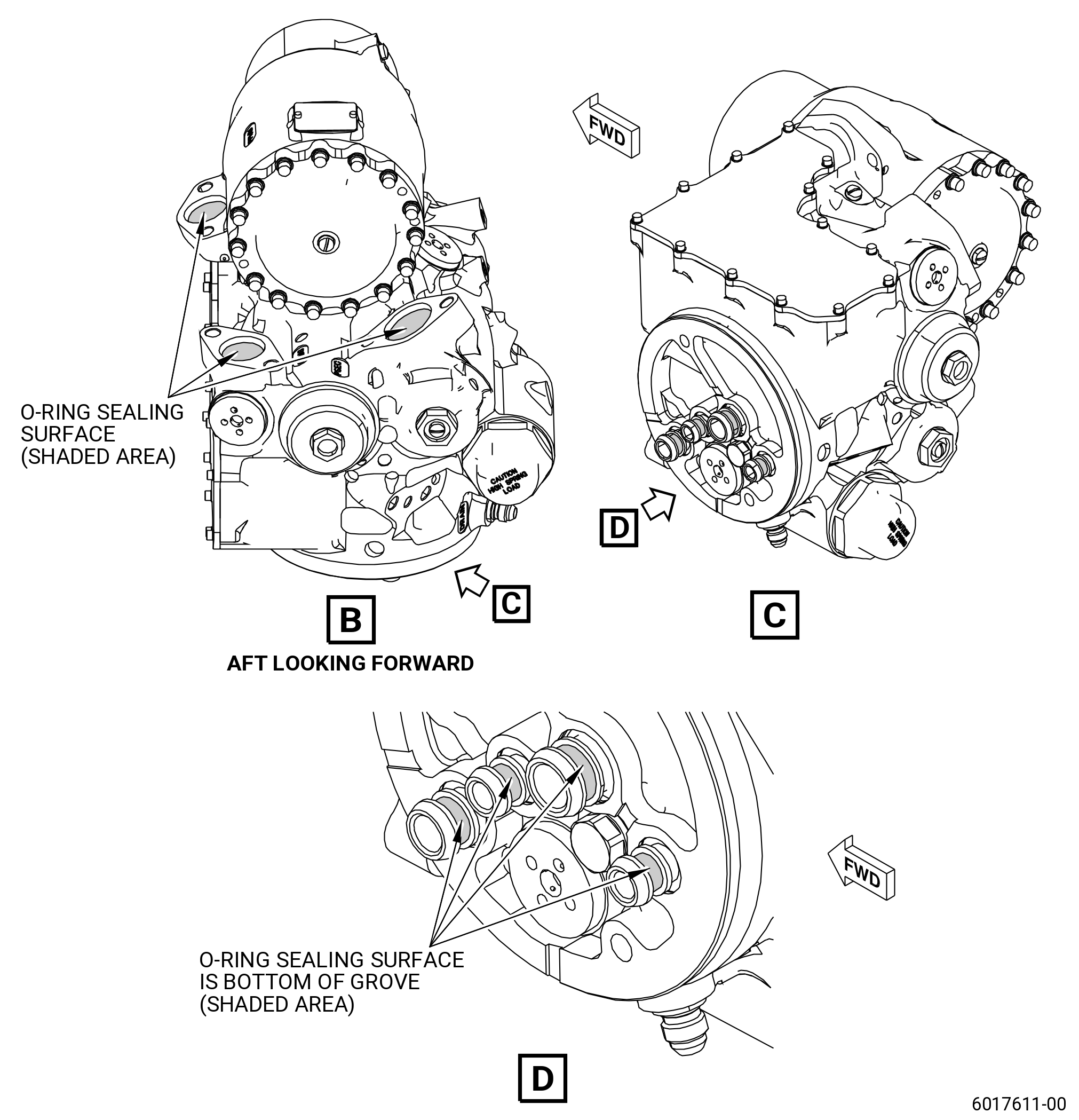
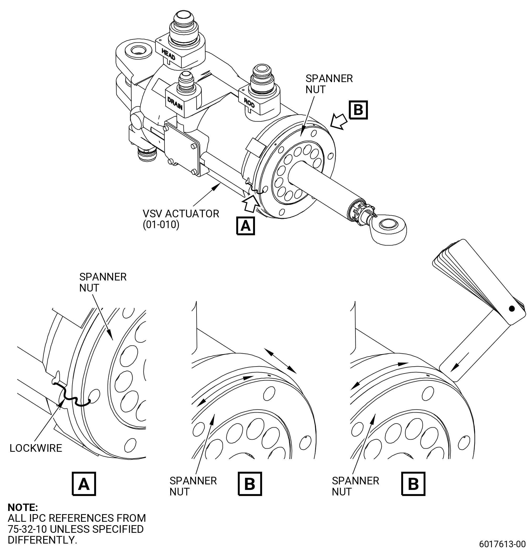
| (b) | Spanner nut inspection. Refer to Figure 806. |
| 1 | Inspect the lockwire holding the spanner nut to the housing of the VSV actuator. |
| 2 | Move the spanner nut (axially and radially) manually in order to find looseness between the spanner nut and the actuator housing. |
| 3 | Use a filler gage 0.002 inch (0.05 mm) to examine any possible gaps between the actuator housing and the spanner nut. |
| NOTE: |
|
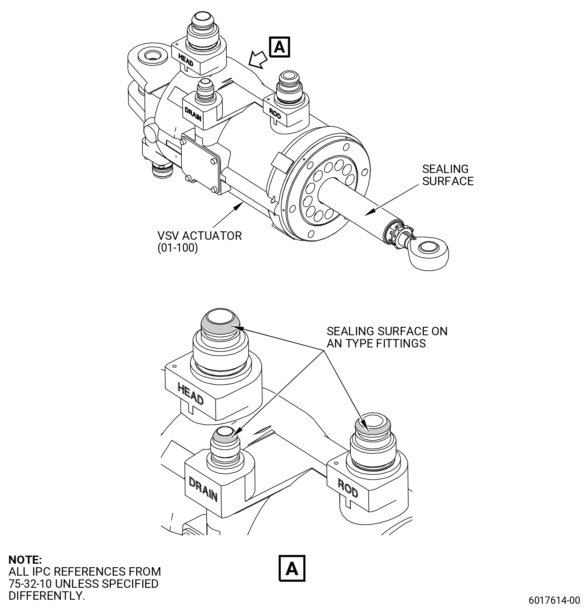
| 4 | Sealing surfaces inspection. Sealing surfaces are defined as those surfaces that are in contact with a mating seal (o-ring, packing, metal-to-metal). Refer to Figure 807. |
| 5 | Do an inspection of the sealing surfaces within the seal contact area for scratches or raised material. |
| NOTE: |
|
| 6 | Examine the condition of conical sealing surfaces on the AN type fittings. No defects are permitted in the center 60 percent conical seal surface. |
| Subtask 72-00-00-220-164 |
| (6) | Do a visual inspection of the alternator stator (01-010 , 73-21-60) (SIN 65301) as follows: |
| (a) | Do a visual inspection to the exterior of the alternator stator (01-010 , 73-21-60) (SIN 65301) for: |
| 1 | Scuffs in the ablative coating with no metal exposed or metal exposed so that there is no more than 1.00 inch (25.4 mm) in diameter can be repaired. If more than 10 percent of the stator surface is exposed, the ablative coating can not be repaired. |
| 2 | Sliced ablative coating where no metal is exposed can be repaired. |
| 3 | Connector pins bent. |
| 4 | Connector threads damaged. |
| NOTE: |
|
| (b) | If the visual inspection check fails for ablative coating damage, repair the alternator stator ablative coating. Refer to CMM 73-22-10. |
| Subtask 72-00-00-220-173 |
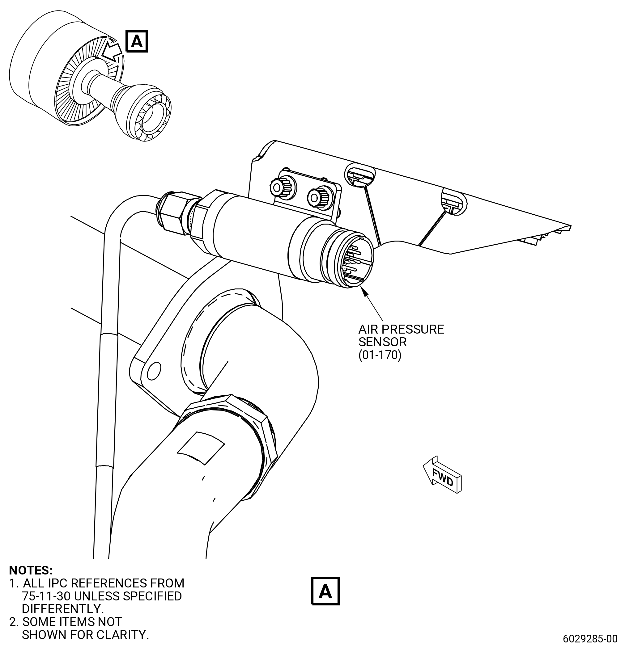
| (7) | Do a visual inspection of the air pressure sensor (01-170 , 75-11-30) (SIN 63701). Refer to Figure 803 and as follows: |
| (a) | Do a visual inspection to the main body of the air pressure sensor (01-170 , 75-11-30) (SIN 63701) for: |
| 1 | Dents or scratches less than or equal to 0.016 in. (0.41 mm) in depth are permitted. |
| 2 | Connector pins bents. |
| 3 | Connector threads damaged. |
| NOTE: |
|
| (b) | If the sensor fails the visual inspection, replace the sensor. |
| Subtask 72-00-00-220-172 |
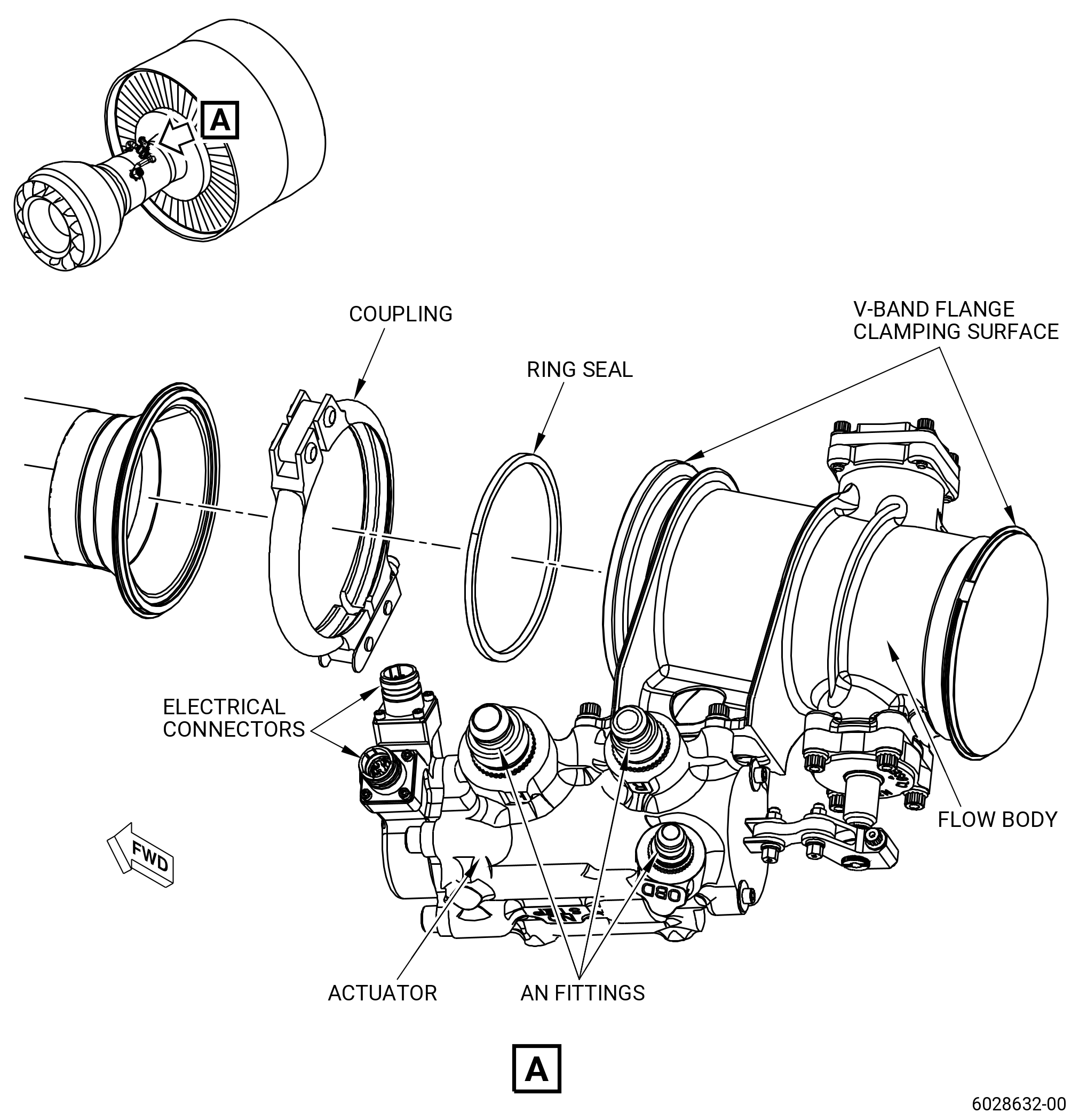
| (8) | Do a visual inspection for the transient bleed valve (TBV) (01-010 , 75-31-11) (SIN 60700) and (01-011 , 75-31-11) (SIN 60700). Refer to Figure 808 and as follows: |
| (a) | Do a visual inspection of the external surfaces of the flow body and actuator. |
| 1 | Machined or cast surfaces for cracks, dents, gouges, nicks, grooves or scratches: |
| a | Parts with defects that have raised material can be repaired by removing the raised material. Refer to TASK 70-42-00-350-002 (BLENDING AND REMOVAL OF HIGH METAL PROCEDURES). |
| b | If no repair is available, defects more than 0.010 inch (0.25 mm) in depth or in height can be a cause of rejection. |
| c | Repair surface finish if blending performed on aluminum valve body. Refer to TASK 70-43-07-380-007 (CHEMICAL TOUCH-UP SURFACE REFINISHING PROCESS FOR ALUMINUM). |
| 2 | Flow body clamp mating surfaces (non-seal side) of the V-style flange for high metal, nicks, scratches, and gouges: |
| a | Parts with defects that have raised material can be repaired by removing the raised material. Refer to TASK 70-42-00-350-002 (BLENDING AND REMOVAL OF HIGH METAL PROCEDURES). |
| b | If no repair is available, defects more than 0.040 inch (1.00 mm) in depth or 0.005 inch (0.12 mm) in height can be a cause of rejection. |
| 3 | Sealing surfaces are defined as those surfaces that are in contact with a mating seal (o-ring, packing, metal-to-metal). Examples are AN fittings and AS1895 ring seal interface: |
| a | Do an inspection of the AN type fittings o-ring grooves for damage of the sealing surface. |
| b | Do an inspection of the AN type fittings conical sealing surface. No defects are permitted in the center 60 percent conical seal surface. |
| c | Do an inspection of the flow body sealing surfaces for AN ring seals. No defects are permitted. |
| NOTE: |
|
| 4 | Connector pins bent. |
| 5 | Connector threads damaged. |
| NOTE: |
|
| (b) | If the visual inspection check fails, replace the TBV. |
| Subtask 72-00-00-220-170 |
| (9) | Do a visual inspection to the exterior of the electronic engine control (EEC) as follows: |
| (a) | Missing/peeling paint on the chassis is serviceable and permitted. |
| (b) | If missing/peeling paint on the chassis is found, do an inspection for corrosion. |
| (c) | If there is any indication of corrosion, return the part to the vendor. |
| (d) | Refer to the applicable CMM for further serviceability assessment. |
| Subtask 72-00-00-220-171 |
| (10) | Do a visual inspection to the exterior of the engine maintenance unit (EMU) as follows: |
| (a) | Missing/peeling paint on the chassis is serviceable and permitted. |
| (b) | If missing/peeling paint on the chassis is found, do an inspection for corrosion. |
| (c) | If there is any indication of corrosion, return the part to the vendor. |
| (d) | Refer to the applicable CMM for further serviceability assessment. |
| Subtask 72-00-00-220-174 |
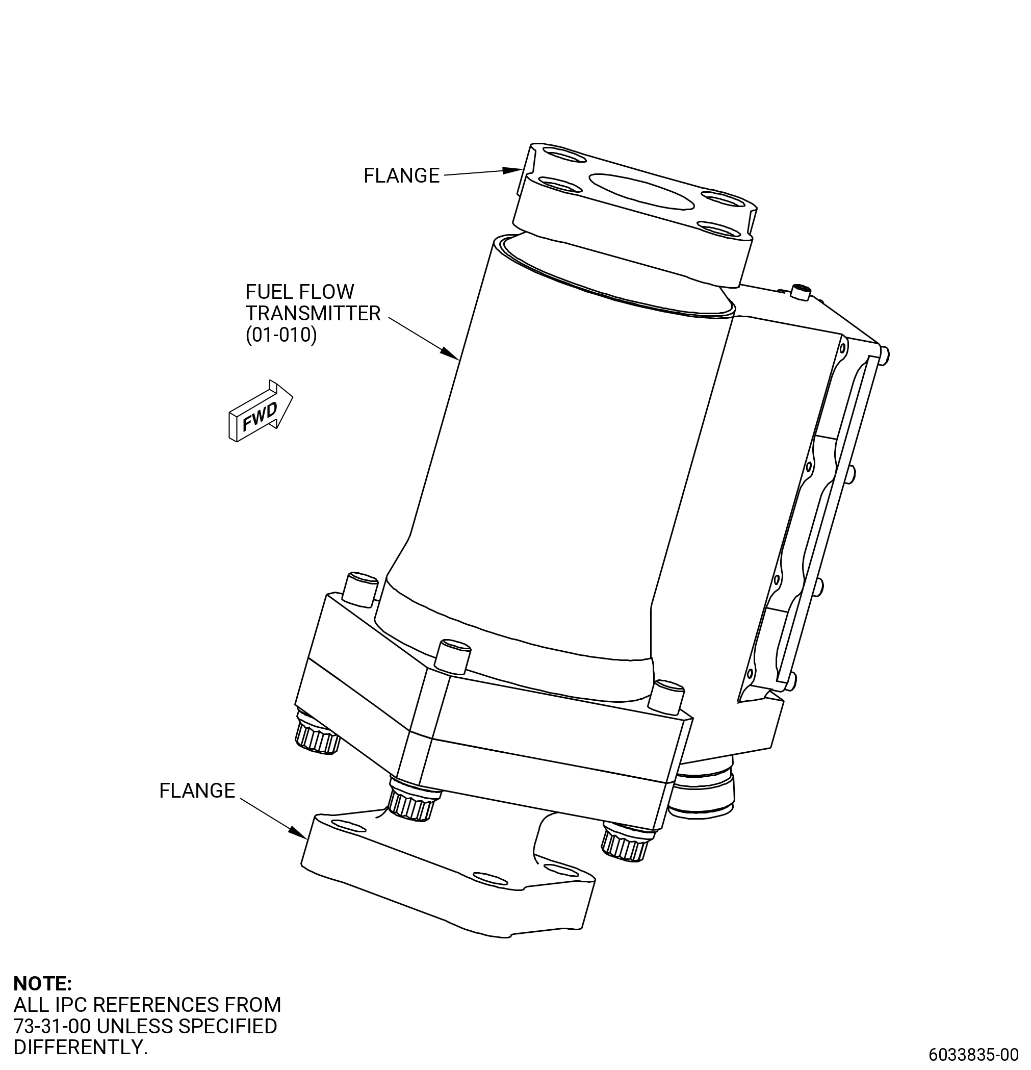
| (11) | Do a visual inspection of the fuel flow transmitter (01-010 , 73-31-00) (SIN 30800). Refer to Figure 809 and as follows: |
| (a) | Do a visual inspection to the flange of the fuel flow transmitter (01-010 , 73-31-00) (SIN 30800) for: |
| 1 | Damage to fuel flow transmitter flange area that are not sealing surfaces: |
| a | Do an inspection for cracks, dents, gouges, nicks, grooves, or scratches. |
| b | Parts with defects that have raised material can be repaired when the raised material is removed. Refer to TASK 70-42-00-350-002 (BLENDING AND REMOVAL OF HIGH METAL PROCEDURES). If no repair is available, defects greater than 0.040 inch (1.0 mm) in depth or in height can be a cause for rejection. |
| c | Repair surface finish. Refer to TASK 70-43-07-380-007 (CHEMICAL TOUCH-UP SURFACE REFINISHING PROCESS FOR ALUMINUM). |
| (b) | If the visual inspection fails check and cannot be repaired, replace the fuel flow transmitter. |