| GENX-1B CLEANING,INSPECTION,AND REPAIR MANUAL | Dated: 02/27/2020 | |
| CIR 72-00-01 , REPAIR 010 | ||
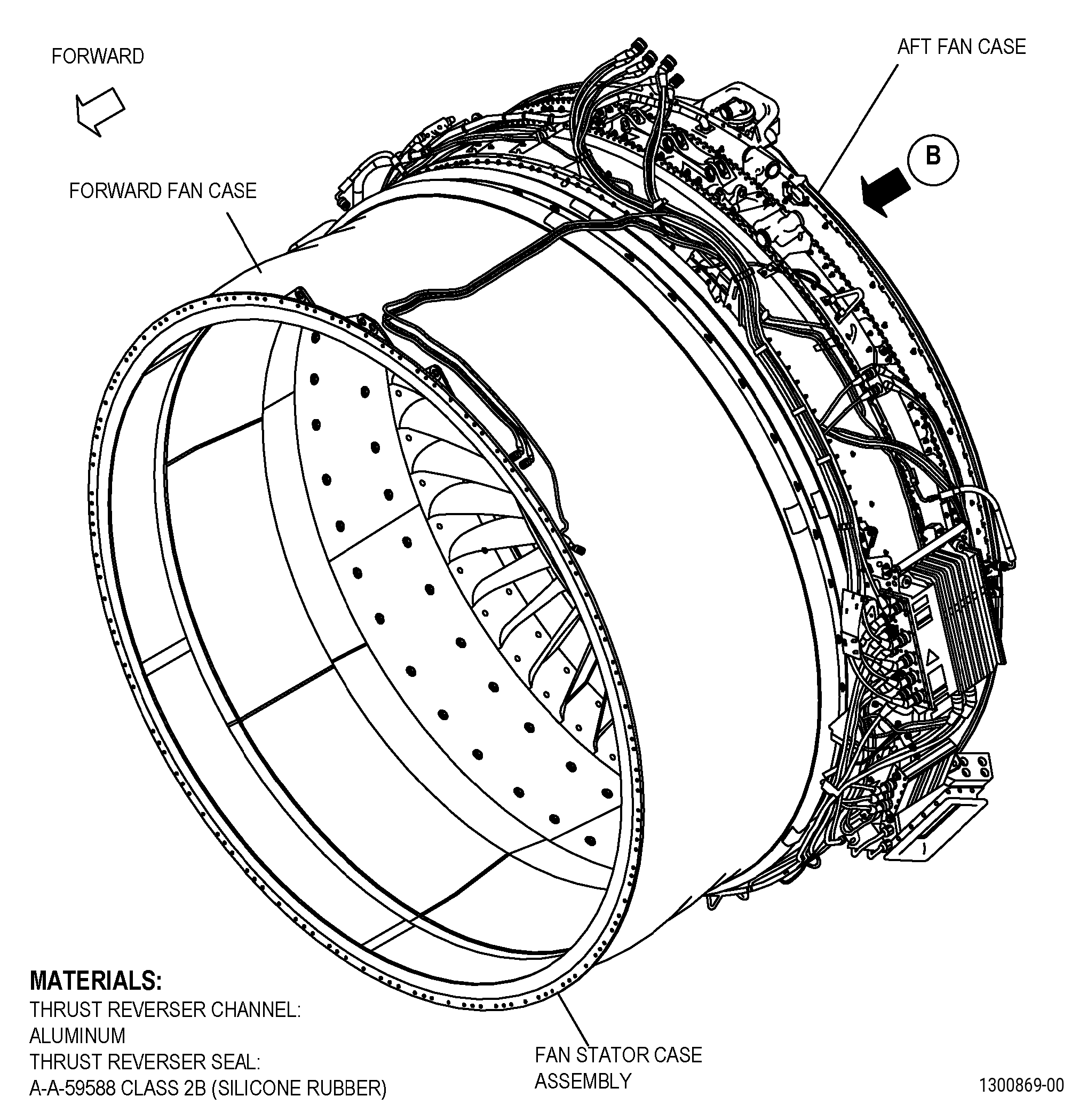
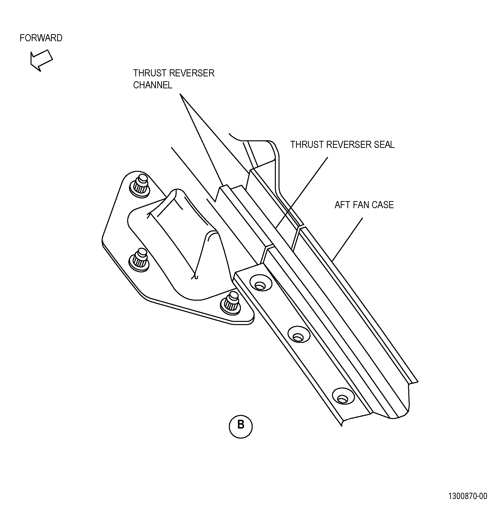
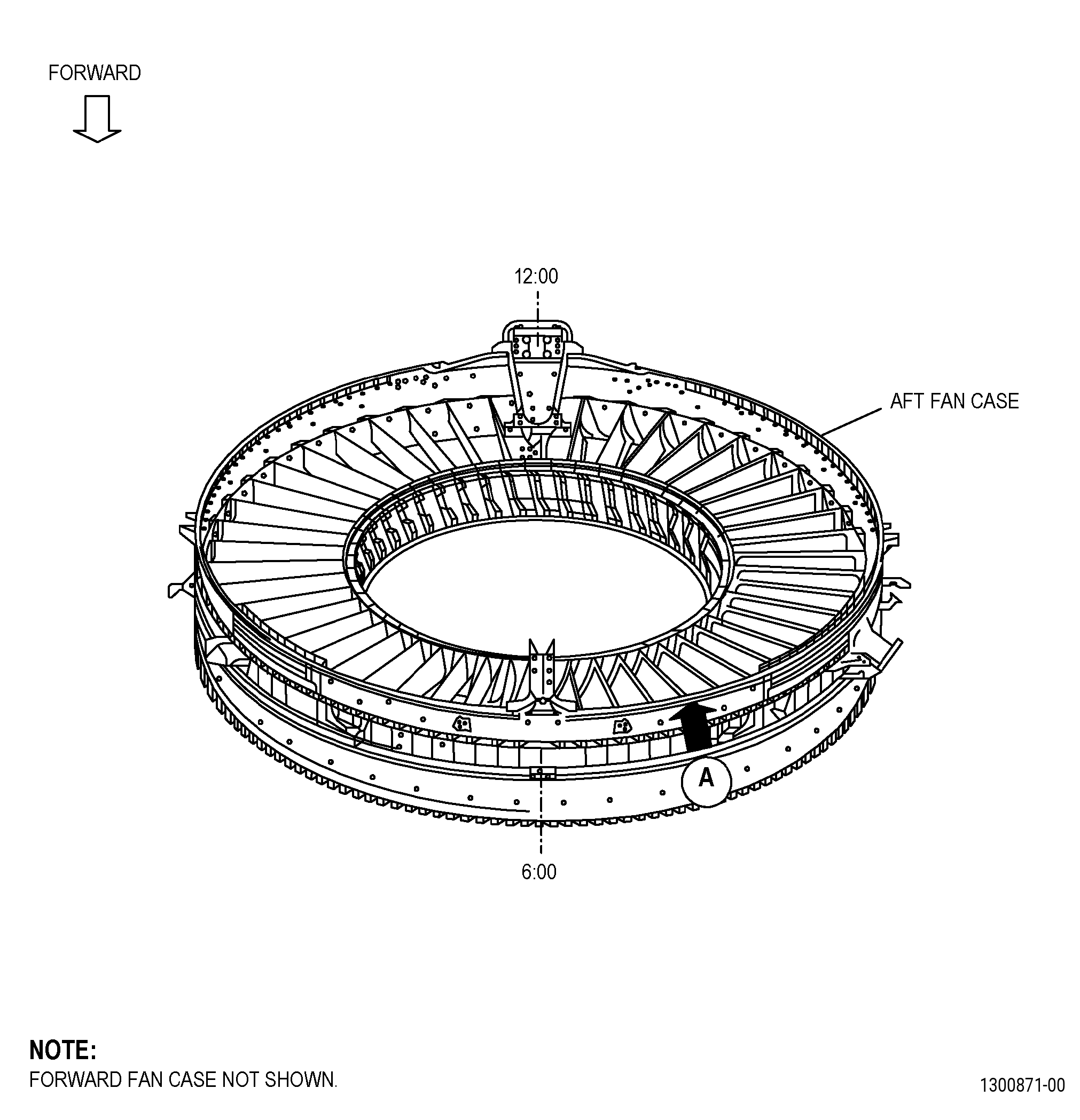
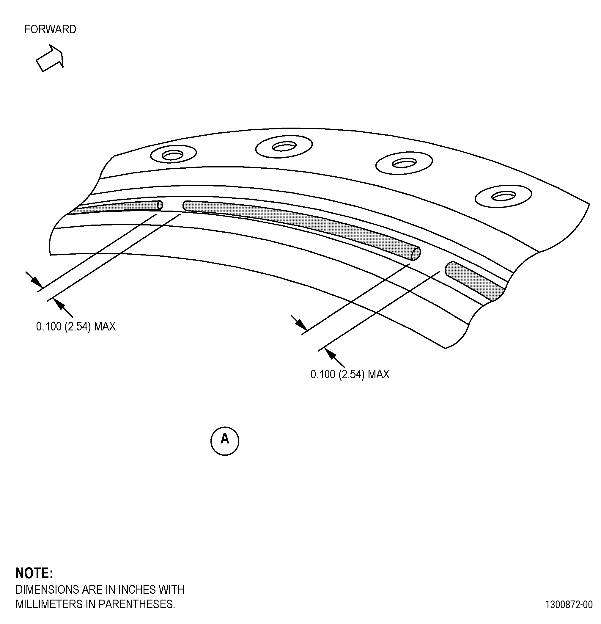
| FAN STATOR MODULE ASSEMBLY - REPAIR - THRUST REVERSER SEAL REPAIR | ||
| GENX-1B CLEANING,INSPECTION,AND REPAIR MANUAL | Dated: 02/27/2020 | |
| CIR 72-00-01 , REPAIR 010 | ||
| FAN STATOR MODULE ASSEMBLY - REPAIR - THRUST REVERSER SEAL REPAIR | ||
| * * * FOR ALL |
| TASK 72-00-01-300-804 |
| 1 . | Repair for the Fan Stator Module Assembly. |
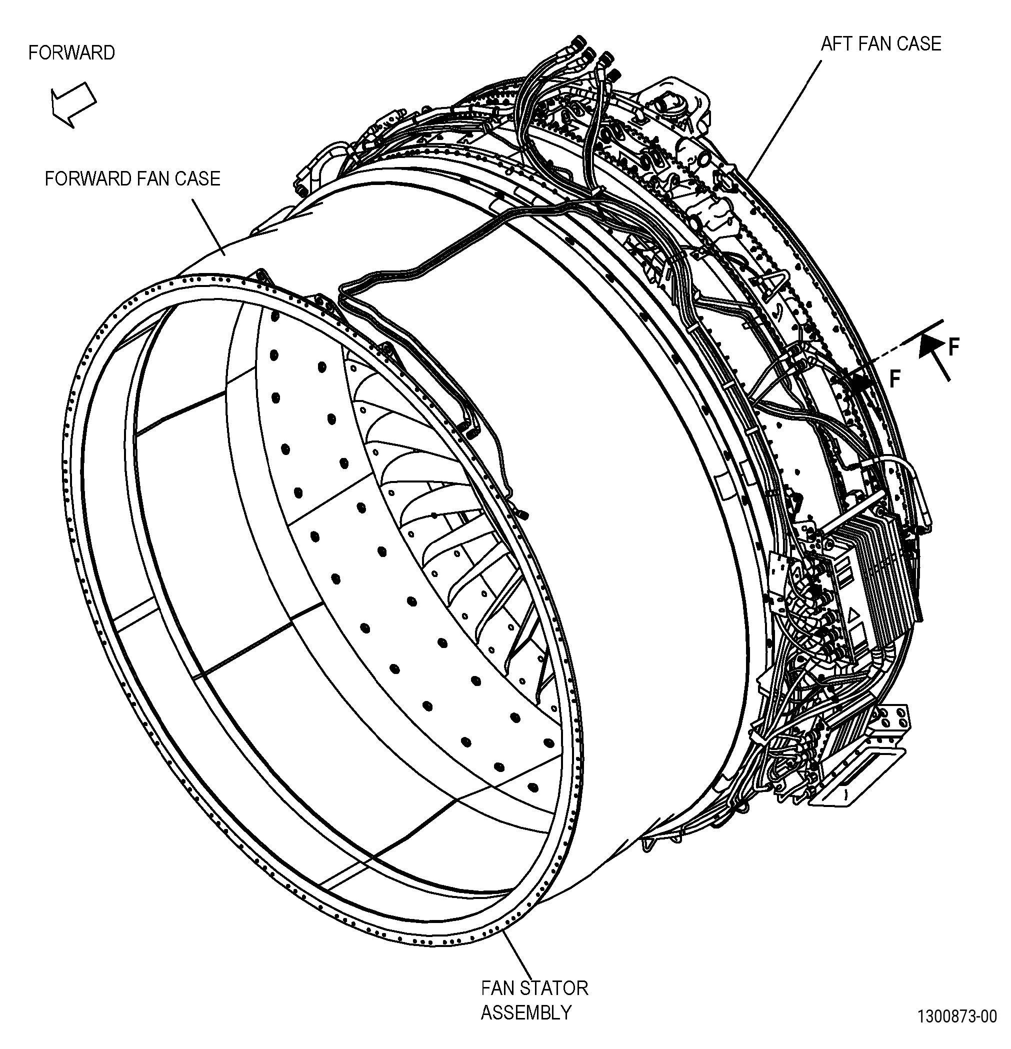
| A. | This procedure gives instructions to repair the fan stator module assembly by removing and replacing the damaged sections of the thrust reverser seal or the full thrust reverser seal with a SPD part. Refer to Figure 901. |
| B. | The following maximum repairable limits apply to this repair: |
| NOTE: |
|
| (4) | Visual Inspection. |
| (u) | Do an inspection of the thrust reverser seal for: |
| 1 | Wear and abrasions: |
| Maximum repairable limit: |
|
| 2 | Punctures, cracks, and tears through the fabric: |
| Maximum repairable limit: |
|
| 3 | Cuts and tears in the pressurization tube: |
| Maximum repairable limit: |
|
| C. | The subsequent table gives a list of the part numbers that are applicable to this repair. All part numbers are applicable to all paragraphs unless specified differently. |
|
|||||||||||||||||||||||||||||||||||||||||||||||||
| D. | Proprietary/Complex Process Statement. |
| (1) | None. |
| 2 . | Tools, Equipment, and Materials. |
| NOTE: |
|
| A. | Tools and Equipment. |
| (1) | Special Tools. None. |
| (2) | Standard Tools and Equipment. None. |
| (3) | Locally Manufactured Tools. None. |
| B. | Consumable Materials. |
| C. | Referenced Procedures. |
|
| D. | Expendable Parts. None. |
| E. | SPD Information. |
|
| F. | Special Solutions. None. |
| G. | Test Specimens. None. |
| 3 . | Dimensional Information. |
| Subtask 72-00-01-220-135 |
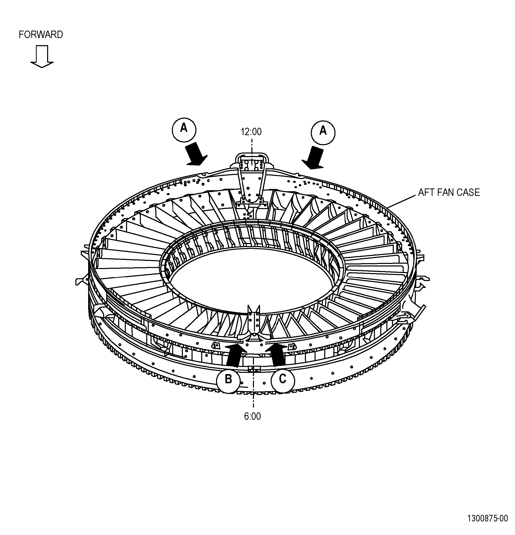
| A. | Refer to Figure 901, Figure 902, and Figure 904 for specified dimensions and locations. |
| NOTE: |
|
| 4 . | Setup Information. |
| None. |
| 5 . | Procedure. |
| Subtask 72-00-01-350-075 |
| A. | Remove the damaged section of the thrust reverser seal or the full thrust reverser seal from the thrust reverser channel as follows: |
| WARNING: |
|
| (1) | Cut the thrust reverser seal to remove the damaged section or the full seal from the V-groove of the thrust reverser channel. |
| (2) | Remove the damaged section of the thrust reverser seal or the full seal from the thrust reverser channel. |
| Subtask 72-00-01-110-018 |
| B. | Clean the thrust reverser channel V-groove repair area. Refer to TASK 70-21-00-110-051 (CHEMICAL CLEANING), TASK 70-21-23-110-053 (CLEANING METHOD 23 - HAND-WIPE DEGREASING), and as follows: |
| Subtask 72-00-01-160-014 |
| WARNING: |
|
| (1) | Use compressed air to remove loose dirt from the V-groove repair area. |
| Subtask 72-00-01-110-019 |
| WARNING: |
|
| (2) | Use a C10-182 cleaning cloth wet with C04-035 isopropyl alcohol to clean the thrust reverser channel V-groove repair area. |
| WARNING: |
|
| (3) | Let the C04-035 isopropyl alcohol dry for a minimum of 5 minutes. |
| Subtask 72-00-01-210-001 |
| C. | If you replace a section of the thrust reverser seal, do a fit check of the thrust reverser SPD seal (01-080 , 72-21-00) that you will install in the V-groove of the thrust reverser channel repair area. Refer to Figure 902 and as follows: |
| Subtask 72-00-01-220-136 |
| (1) | Measure and record the length of the missing section of the thrust reverser seal. |
| Subtask 72-00-01-350-076 |
| WARNING: |
|
| (2) | Cut a section of thrust reverser SPD seal to the length that you recorded in Subtask 72-00-01-220-136 (paragraph 5.C.(1)). |
| (3) | Install the section of the thrust reverser SPD seal in the V-groove of the thrust reverser channel, and use C10-067 platers tape to hold it in position. |
| Subtask 72-00-01-220-137 |
| (4) | Do an inspection of the clearance between the sections of the thrust reverser SPD seal and the adjacent seals that are not damaged. |
| Subtask 72-00-01-350-078 |
| (5) | Remove the platers tape from the thrust reverser channel. |
| (6) | Remove the section of the thrust reverser SPD seal from the thrust reverser channel. |
| Subtask 72-00-01-350-080 |
| D. | Apply C10-067 platers tape to the V-groove of the thrust reverser channel repair areas. Refer to Figure 903. |
| NOTE: |
|
| Subtask 72-00-01-350-081 |
| WARNING: |
|
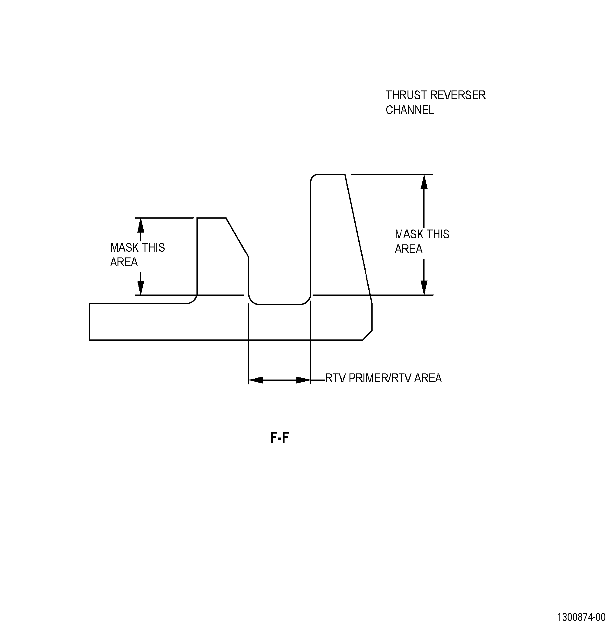
| E. | Apply the C01-159 RTV primer along the length of the V-groove of the thrust reverser channel repair areas. Refer to Figure 903. |
| Subtask 72-00-01-350-082 |
| F. | Alternative Procedure Available. Apply C01-178 RTV in the V-groove of the thrust reverser channel repair areas. Refer to Figure 903 and do as follows: |
| (1) | Use a Teflon spatula approximately 0.4 inch (10 mm) in width. |
| (2) | Apply a layer to a maximum of 0.05 inch (1.2 mm) in thickness. |
| NOTE: |
|
| Subtask 72-00-01-350-327 |
| F.A. | Alternative Procedure. Apply C01-122 RTV in the V-groove of the thrust reverser channel repair areas. Refer to Figure 903 and do as follows: |
| (1) | Use a Teflon spatula approximately 0.4 inch (10 mm) in width. |
| (2) | Apply a layer to a maximum of 0.05 inch (1.2 mm) in thickness. |
| NOTE: |
|
| Subtask 72-00-01-350-083 |
| G. | Remove the platers tape from the V-groove of the thrust reverser channel repair areas. |
| Subtask 72-00-01-350-084 |
| H. | Install the thrust reverser SPD seal (01-080 , 72-21-00) in the V-groove of the thrust reverser channel repair areas. |
| Subtask 72-00-01-350-085 |
| I. | Use C10-067 platers tape to hold the thrust reverser SPD seal (01-080 , 72-21-00) in the V-groove of the thrust reverser channel repair areas. |
| Subtask 72-00-01-350-086 |
| J. | Alternative Procedure Available. Let the C01-178 RTV cure for a minimum of 1 hour. |
| Subtask 72-00-01-350-328 |
| J.A. | Alternative Procedure. Let the C01-122 RTV cure for a minimum of 1 hour. |
| Subtask 72-00-01-350-087 |
| K. | Remove the platers tape from the V-groove of the thrust reverser channel repair areas. |
| Subtask 72-00-01-350-088 |
| WARNING: |
|
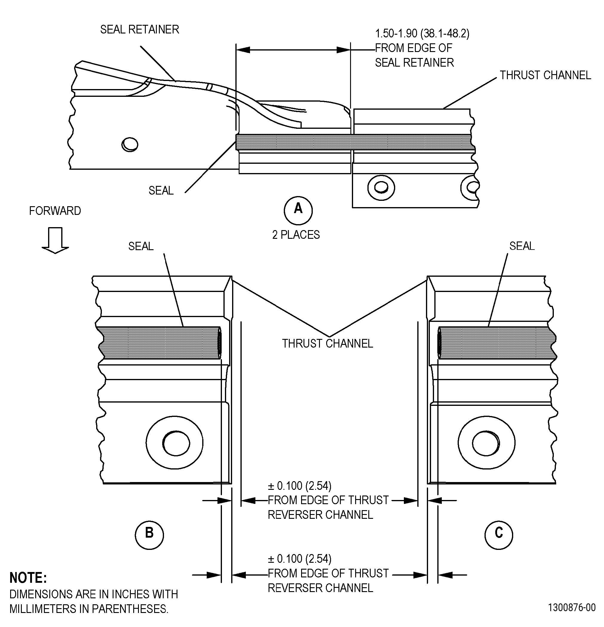
| L. | If you replace the full thrust reverser seal, cut the thrust reverser SPD seal (01-080 , 72-21-00) to the correct length. Refer to Figure 904 and as follows: |
| (1) | Cut the thrust reverser SPD seals to the correct dimension from the edge of the seal retainers. |
| (2) | Cut the thrust reverser SPD seals to the correct dimension from the edge of the thrust reverser channels. |