| GENX-1B CLEANING,INSPECTION,AND REPAIR MANUAL | Dated: 04/30/2017 | |
| CIR 72-00-01 , REPAIR 012 | ||
| FAN STATOR MODULE ASSEMBLY - REPAIR - FIRE SHIELDS AND INSULATION BLANKET REPLACEMENT ON FIREWALLS | ||
| GENX-1B CLEANING,INSPECTION,AND REPAIR MANUAL | Dated: 04/30/2017 | |
| CIR 72-00-01 , REPAIR 012 | ||
| FAN STATOR MODULE ASSEMBLY - REPAIR - FIRE SHIELDS AND INSULATION BLANKET REPLACEMENT ON FIREWALLS | ||
| * * * FOR ALL |
| TASK 72-00-01-300-818 |
| 1 . | Fire Shields And Insulation Blanket Replacement On Firewalls. |
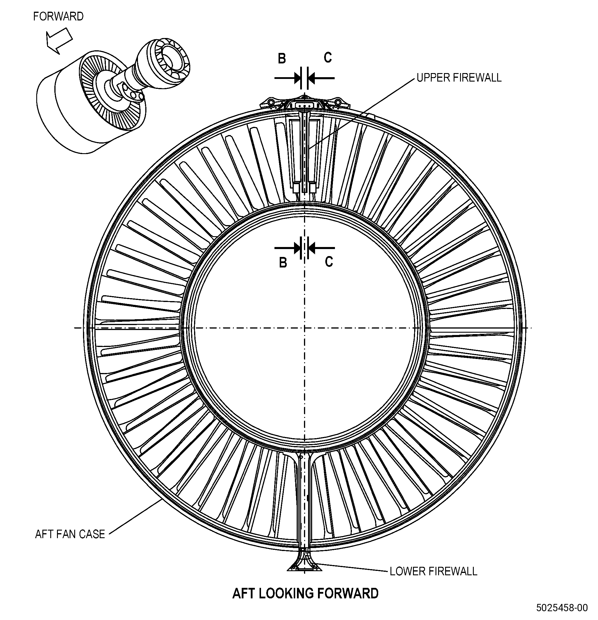
| A. | This procedure gives instructions to repair the fan stator module assembly (fan stator module) by replacing damaged or missing fire shield(s)/insulation blanket on firewall(s). Refer to Figure 901. |
| B. | The following maximum repairable limits apply to this repair: |
| NOTE: |
|
| (4) | Visual Inspection. |
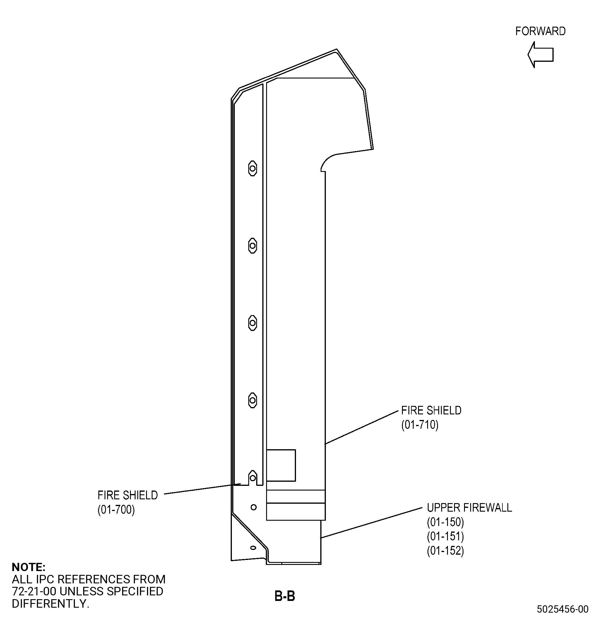
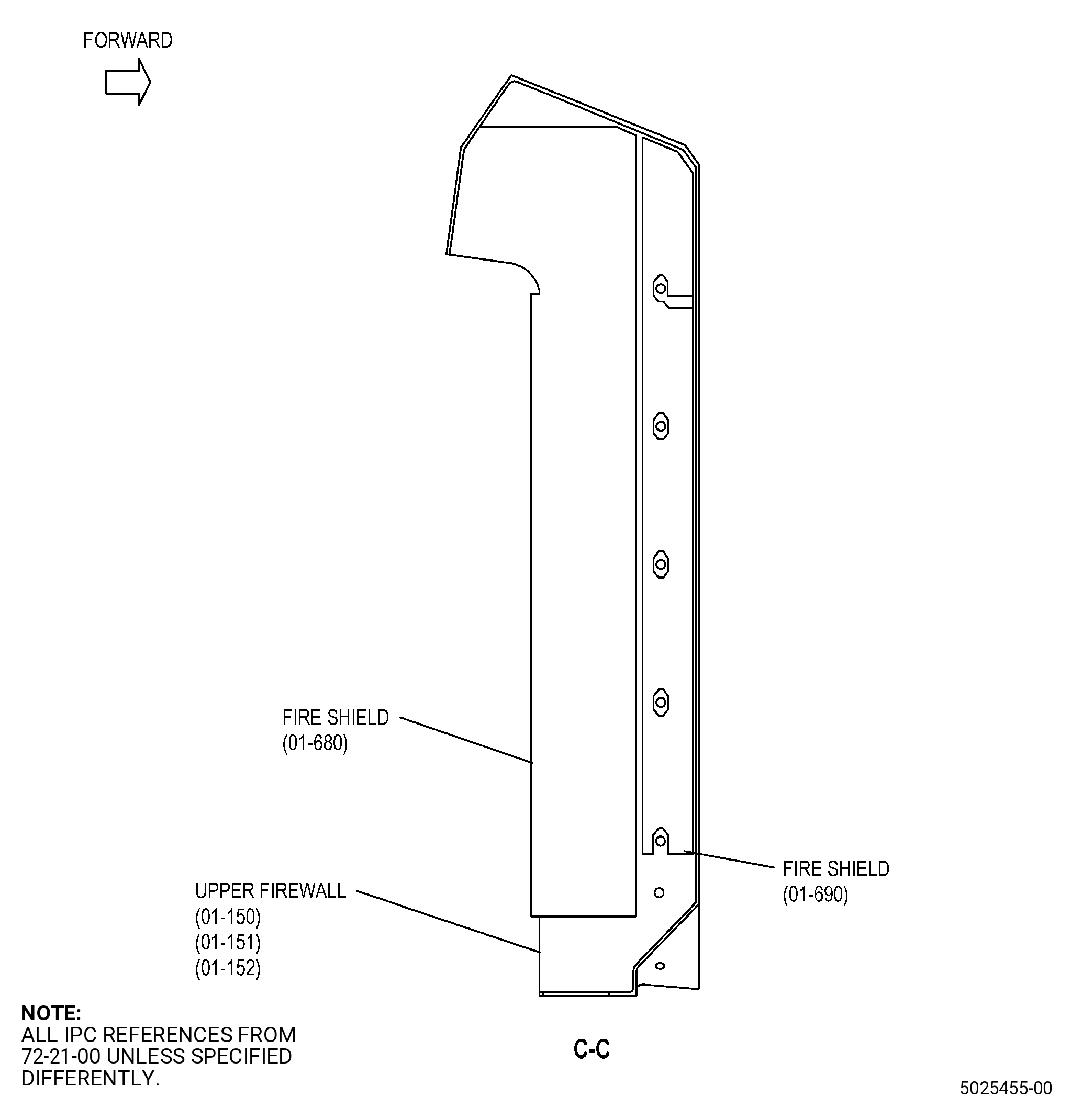
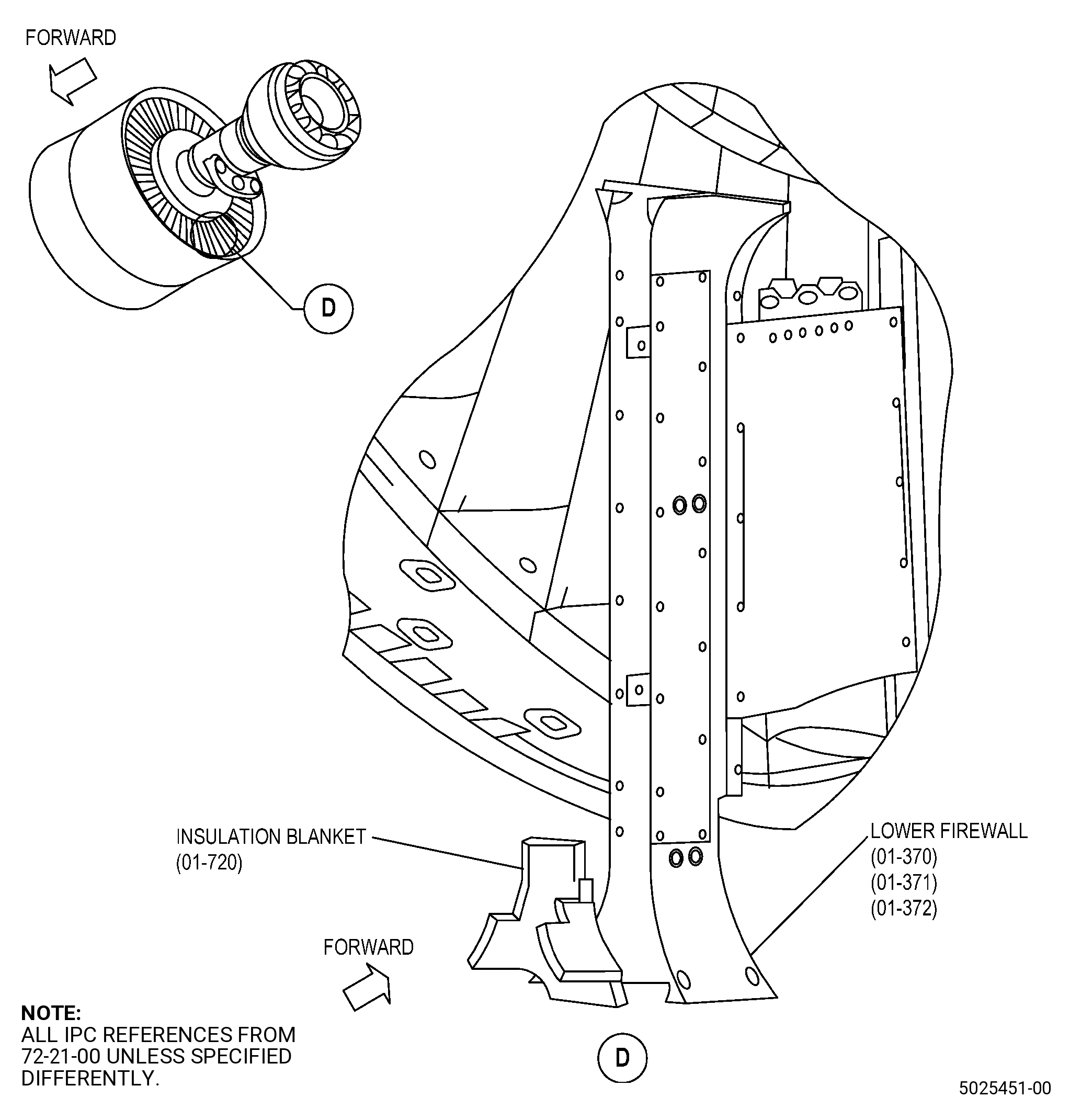
| (aa) | Do an inspection of each fire shield (01-680 , 72-21-00) (SIN 844A1), (01-690 , 72-21-00) (SIN 844A2), (01-700 , 72-21-00) (SIN 844A3), (01-710 , 72-21-00) (SIN 844A4) on the upper firewall (01-150 , 72-21-00) (SIN 84401), (01-151 , 72-21-00) (SIN 84401), (01-152 , 72-21-00) (SIN 84401) and the insulation blanket (01-720 , 72-21-00) (SIN 844A5) on the lower firewall (01-370 , 72-21-00) (SIN 84501), (01-371 , 72-21-00) (SIN 84501), (01-372 , 72-21-00) (SIN 84501) for: |
| 1 | Loose, missing, or torn fire shield and/or insulation blanket aluminum foil: |
| Maximum repairable limit: |
|
| 2 | Gouges in fire shield and/or insulation blanket with the same depth as the outer glass fiber layer or red RTV: |
| Maximum repairable limit: |
|
| 3 | Gouges in fire shield and/or insulation blanket with the same depth as the inner glass fiber layer or white insulation material: |
| Maximum repairable limit: |
|
| 4 | Missing or non-repairable fire shield(s) and/or insulation blanket: |
| Maximum repairable limit: |
|
| C. | The subsequent table gives a list of the part numbers that are applicable to this repair. All part numbers are applicable to all paragraphs unless specified differently. |
|
||||||||||||||||||||||||||||||||||||
| D. | Proprietary/Complex Process Statement. |
| (1) | None. |
| 2 . | Tools, Equipment, and Materials. |
| NOTE: |
|
| A. | Tools and Equipment. |
| (1) | Special Tools. None. |
| (2) | Standard Tools and Equipment. |
|
| (3) | Locally Manufactured Tools. None. |
| WARNING: |
|
| B. | Consumable Materials. |
| C. | Referenced Procedures. |
|
| D. | Expendable Parts. None. |
| E. | SPD Information. |
|
| F. | Special Solutions. None. |
| G. | Test Specimens. None. |
| 3 . | Dimensional Information. |
| Subtask 72-00-01-220-338 |
| A. | Refer to Figure 901, Figure 902, and Figure 903 for specified dimensions and locations. |
| NOTE: |
|
| NOTE: |
|
| 4 . | Setup Information. |
| None. |
| 5 . | Procedure. |
| Subtask 72-00-01-110-060 |
| A. | Alternative Procedure Available. Clean the fan stator module. Refer to TASK 70-21-00-110-051 (CHEMICAL CLEANING), TASK 70-21-03-160-001 (CLEANING METHOD NO. 3 - STEAM CLEANING), and as follows: |
| (1) | Make sure to remove all the oil, grease, and dirt from the fan stator module. |
| Subtask 72-00-01-110-061 |
| A.A. | Alternative Procedure. Clean the fan stator module. Refer to TASK 70-21-00-110-051 (CHEMICAL CLEANING), TASK 70-21-01-110-001 (CLEANING METHOD NO. 1 - SOLVENT DEGREASING), and as follows: |
| (1) | Make sure to remove all the oil, grease, and dirt from the fan stator module. |
| Subtask 72-00-01-350-300 |
| WARNING: |
|
| B. | Remove all damaged fire shields/insulation blanket from the firewall(s) with a razor knife or plastic scraper as follows: |
| (1) | Be careful not to cut into or make gouges in the parent material of the firewall(s) or other serviceable fire shields. |
| (2) | Discard the fire shields that you removed from the firewall(s). |
| Subtask 72-00-01-110-062 |
| C. | Clean all firewall repair areas. Refer to TASK 70-21-00-110-051 (CHEMICAL CLEANING), and TASK 70-21-23-110-053 (CLEANING METHOD NO. 23 - HAND-WIPE DEGREASING). |
| NOTE: |
|
| Subtask 72-00-01-350-312 |
| D. | Remove all remaining adhesive from the firewall repair areas with C10-062 abrasive cloth. |
| Subtask 72-00-01-350-302 |
| E. | Apply masking to all fire shields adjacent to the firewall repair areas. Refer to TASK 70-46-01-350-030 (MASKING AND CLEANING OF EPOXY AND POLYESTER MATRIX THERMOSETTING COMPOSITE MATERIALS), and as follows: |
| (1) | Use Composite Masking Method No. 4. |
| (2) | Use C10-012 tape. |
| Subtask 72-00-01-120-013 |
| F. | Clean the repair areas on the firewall(s). Refer to TASK 70-21-04-120-001 (CLEANING METHOD NO. 4 - DRY ABRASIVE BLAST CLEANING), and as follows: |
| (1) | Use Method No. 4A. |
| (2) | Use C04-113 abrasive grit at a maximum pressure of 45 psi (310 kPa). |
| Subtask 72-00-01-160-044 |
| WARNING: |
|
| G. | Blow the dust from the repair areas of the firewall(s) with clean, dry, compressed air that contains no oil. |
| Subtask 72-00-01-350-304 |
| H. | Clean the bonding surfaces of the firewall(s) and the SPD fire shield(s)/insulation blanket. Refer to TASK 70-46-01-350-030 (MASKING AND CLEANING OF EPOXY AND POLYESTER MATRIX THERMOSETTING COMPOSITE MATERIALS), paragraph 2.E., SPD Information, Figure 901, Figure 902, Figure 903, and do as follows: |
| (1) | Use Composite Cleaning Method No. 4 or Composite Cleaning Method No. 5. |
| Subtask 72-00-01-350-305 |
| I. | Apply C10-040 teflon tape to all the non-bonding surfaces of the SPD fire shield(s)/insulation blanket. Refer to paragraph 2.E., SPD Information, Figure 901, Figure 902, Figure 903, and do as follows: |
| (1) | Make sure that you apply masking to the faces of the SPD fire shield(s)/insulation blanket along their edges. |
| Subtask 72-00-01-350-313 |
| WARNING: |
|
| J. | Apply C01-159 primer to the bonding surfaces of the firewall(s) and the SPD fire shield(s)/insulation blanket. Refer to paragraph 2.E., SPD Information, Figure 901, Figure 902, Figure 903, and do as follows: |
| (1) | Apply C01-159 primer only to the bonding surfaces of one repair area (one 90- degree segment of the firewall and one SPD fire shield/insulation blanket) at a time. |
| (2) | Let the C01-159 primer dry for 1 hour as follows: |
| (a) | Make sure that the SPD fire shield(s)/insulation blanket is bonded to the firewall in 4 hours or less after the C01-159 primer is cured. |
| Subtask 72-00-01-350-306 |
| K. | After the C01-159 primer is cured, apply a thin coating of C01-007 RTV 106 to the bonding surfaces of the SPD fire shield/insulation blanket and the firewall(s). Refer to paragraph 2.E., SPD Information, Figure 901, Figure 902, Figure 903, and do as follows: |
| (1) | Make sure that you assemble the SPD fire shield(s)/insulation blanket to the firewall(s) in 2 minutes or less after you apply the C01-007 RTV 106. |
| Subtask 72-00-01-360-070 |
| L. | Bond the SPD fire shield(s)/insulation blanket to the firewall(s) and find the specific SPD location. Refer to paragraph 2.E., SPD Information, Figure 901, Figure 902, Figure 903, and do as follows: |
| (1) | Assemble the SPD fire shield(s)/insulation blanket to the firewall(s) in 2 minutes after you apply the C01-007 RTV 106. |
| (2) | Visually align the holes in the SPD fire shield(s) with the holes that are in the upper firewall. |
| Subtask 72-00-01-350-308 |
| M. | Prepare the SPD fire shield(s)/insulation blanket for curing and do as follows: |
| (1) | Align the firewall until the SPD fire shield(s)/insulation blanket is at the bottom vertical position. |
| (2) | Remove all unwanted adhesive. |
| (3) | Apply a constant pressure of 2-5 psi (13.8-34.4 kPa) to the SPD fire shield/insulation blanket with clean sand bags for a minimum of 12 hours to prevent movement during curing. |
| Subtask 72-00-01-360-071 |
| N. | Cure the C01-007 RTV 106 in accordance with manufacturer instructions and do as follows: |
| (1) | Let the C01-007 RTV 106 cure for a minimum of 24 hours at a room temperature of 65 to 85°F (18 to 29°C). |
| (2) | Continue the repair and ship the fan stator module assembly before a full curing. |
| Subtask 72-00-01-350-310 |
| O. | Remove the sand bags from the SPD fire shield(s)/insulation blanket. |
| Subtask 72-00-01-220-339 |
| P. | Do an inspection of the SPD fire shield(s)/insulation blanket that you installed and as follows: |
| NOTE: |
|
| (1) | Do a check of the voids between the firewall edges and the edges of the SPD fire shields, and insulation blanket. |
| Subtask 72-00-01-350-314 |
| WARNING: |
|
| (2) | If necessary, cut the edges of the SPD fire shields flush to firewall and do as follows: |
| (a) | Seal all the cut edges with C01-007 RTV 106 and cure in accordance with manufacturer instructions. |
| (3) | Do a check of all internal and external edges of the SPD fire shields and insulation blanket for unbonds, and as follows: |
| (a) | If necessary, add C01-007 RTV 106 to fill voids and unbonds, and do as follows: |
| 1 | After you fill voids and unbonds, remove unwanted material. |
| 2 | Cure in accordance with manufacturer instructions. |
| Subtask 72-00-01-350-311 |
| Q. | Do Subtask 72-00-01-350-313 (paragraph 5.J.) thru Subtask 72-00-01-220-339 (paragraph 5.P.) again for all remaining repair areas of the firewall(s). |
| Subtask 72-00-01-350-315 |
| R. | Remove all masking from the SPD fire shield(s)/insulation blanket that you installed. |