| GENX-1B CLEANING,INSPECTION,AND REPAIR MANUAL | Dated: 04/30/2017 | |
| CIR 72-00-01 , REPAIR 013 | ||
| FAN STATOR MODULE ASSEMBLY - REPAIR - REPAIR OF FIRE SHIELDS ON FIREWALL | ||
| GENX-1B CLEANING,INSPECTION,AND REPAIR MANUAL | Dated: 04/30/2017 | |
| CIR 72-00-01 , REPAIR 013 | ||
| FAN STATOR MODULE ASSEMBLY - REPAIR - REPAIR OF FIRE SHIELDS ON FIREWALL | ||
| * * * FOR ALL |
| TASK 72-00-01-300-817 |
| 1 . | Repair Of Fire Shields On Firewall. |
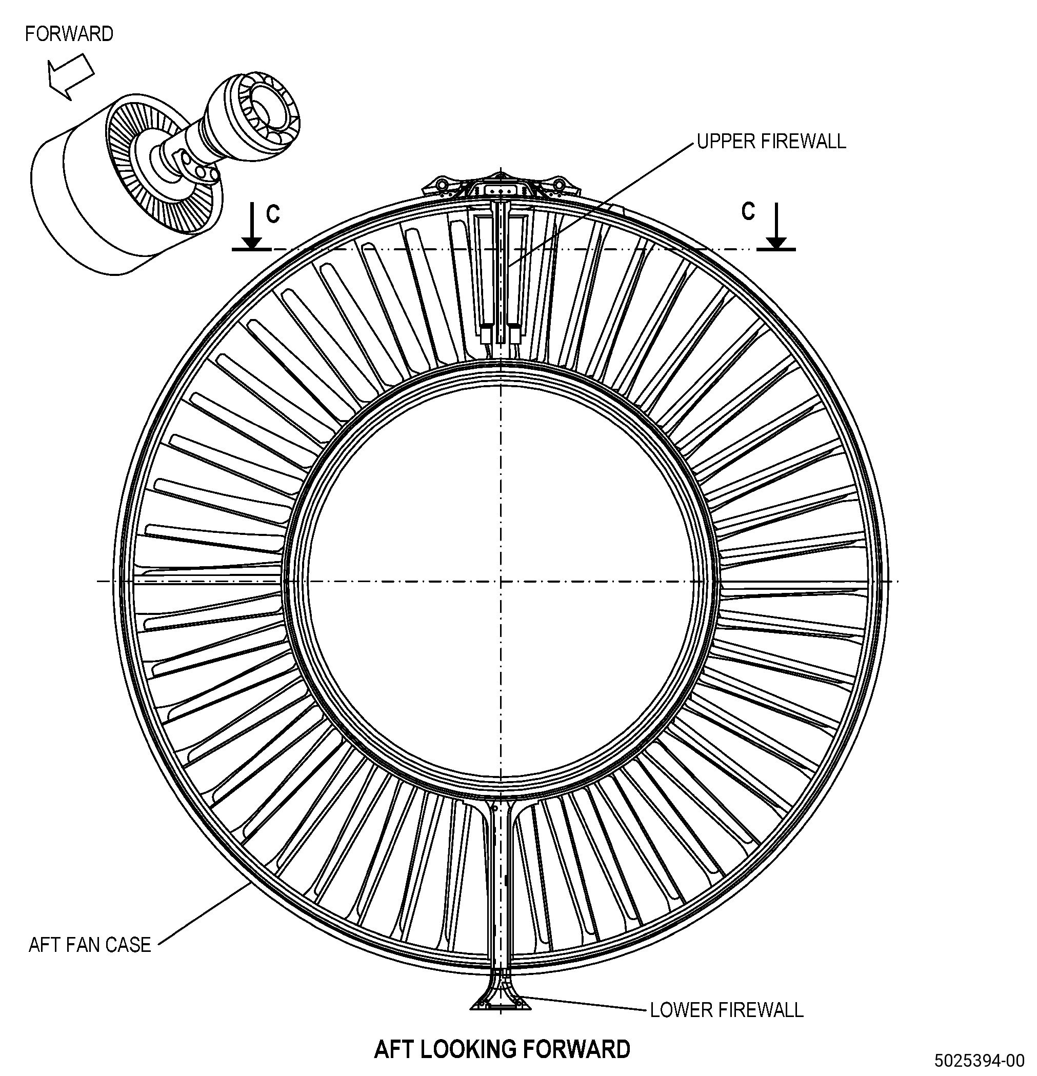
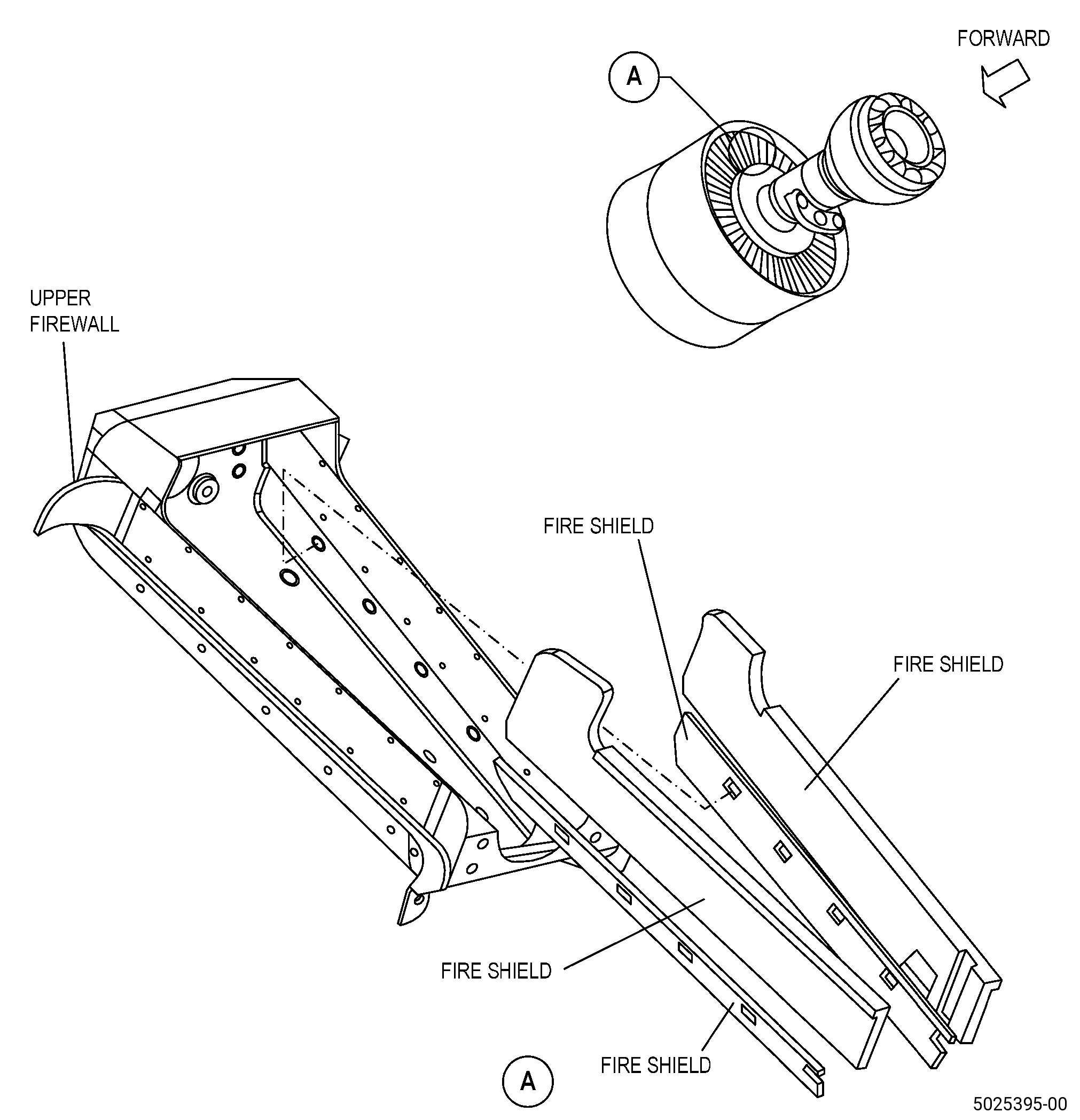
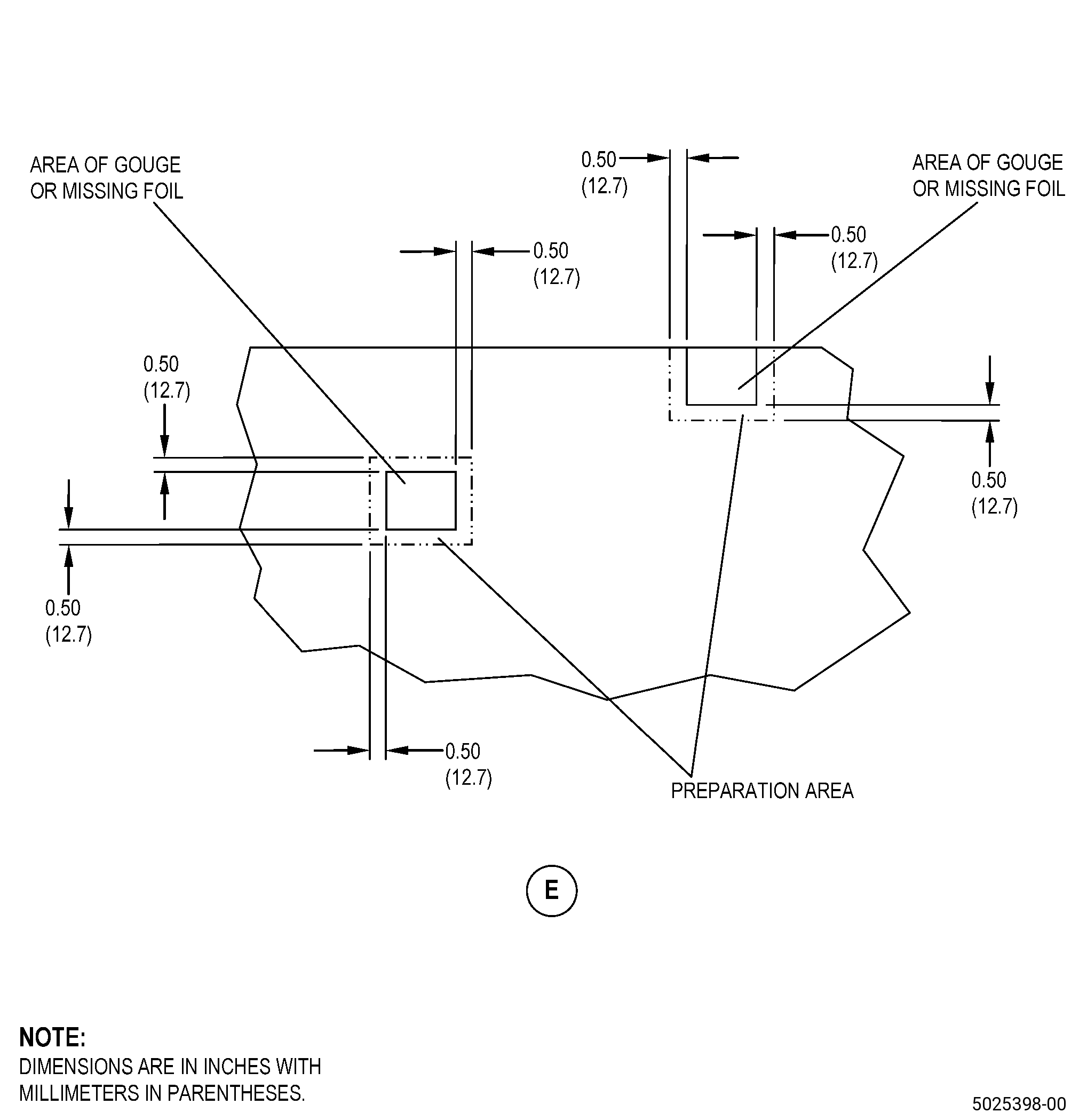
| A. | This procedure gives instructions to repair the fan stator module assembly (fan stator module) by filling in gouges and/or replacing loose, missing, or torn aluminum foil on the fire shield(s). Refer to Figure 901. |
| B. | The following maximum repairable limits apply to this repair: |
| NOTE: |
|
| (4) | Visual Inspection. |
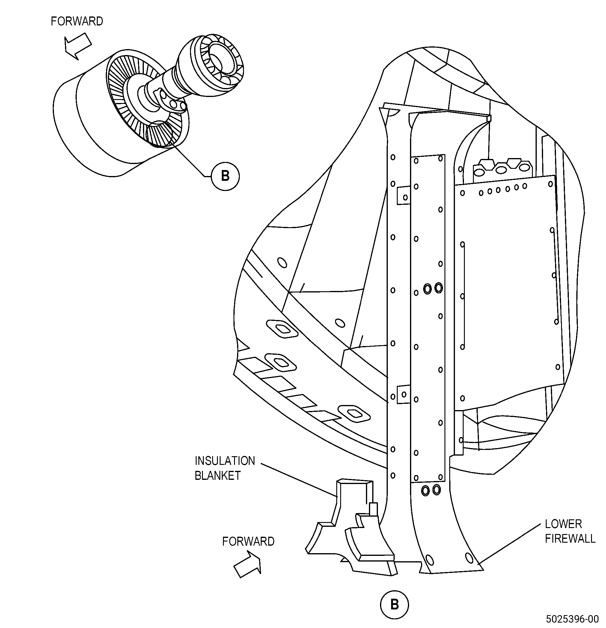
| (aa) | Do an inspection of each fire shield (01-680 , 72-21-00) (SIN 844A1), (01-690 , 72-21-00) (SIN 844A2), (01-700 , 72-21-00) (SIN 844A3), (01-710 , 72-21-00) (SIN 844A4) on the upper firewall (01-150 , 72-21-00) (SIN 84401), (01-151 , 72-21-00) (SIN 84401), (01-152 , 72-21-00) (SIN 84401) and the insulation blanket (01-720 , 72-21-00) (SIN 844A5) on the lower firewall (01-370 , 72-21-00) (SIN 84501), (01-371 , 72-21-00) (SIN 84501), (01-372 , 72-21-00) (SIN 84501) for: |
| 1 | Loose, missing, or torn fire shield aluminum foil: |
| Maximum repairable limit: |
|
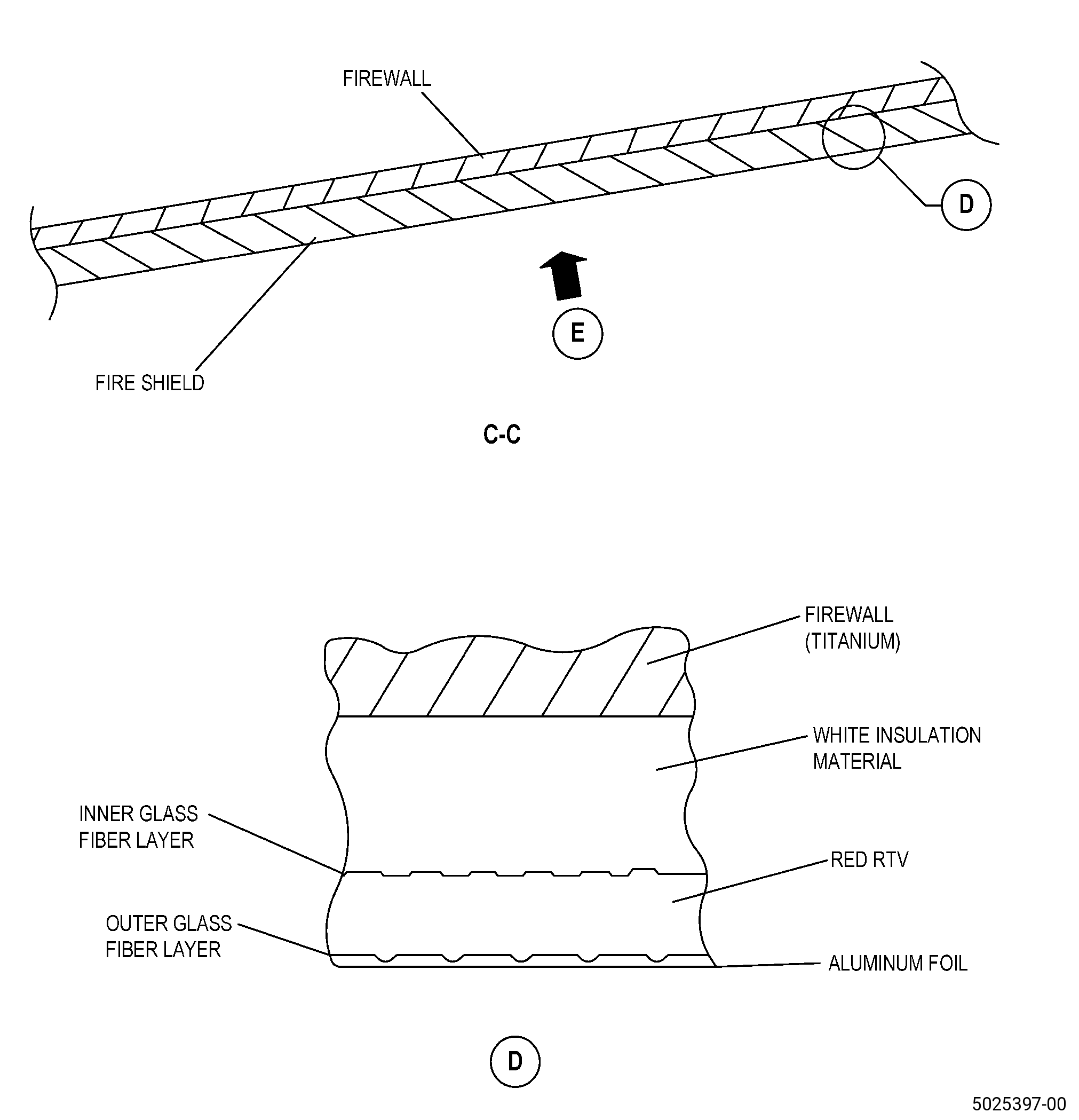
| 2 | Gouges in fire shield with the same depth as the outer glass fiber layer or red RTV: |
| Maximum repairable limit: |
|
| 3 | Gouges in fire shield with the same depth as the inner glass fiber layer or white insulation material: |
| Maximum repairable limit: |
|
| 4 | Missing or non-repairable fire shield(s)/insulation blanket: |
| Maximum repairable limit: |
|
| C. | The subsequent table gives a list of the part numbers that are applicable to this repair. All part numbers are applicable to all paragraphs unless specified differently. |
|
|||||||||||||||||||||||
| D. | Proprietary/Complex Process Statement. |
| (1) | None. |
| 2 . | Tools, Equipment, and Materials. |
| NOTE: |
|
| A. | Tools and Equipment. |
| (1) | Special Tools. None. |
| (2) | Standard Tools and Equipment. None. |
| (3) | Locally Manufactured Tools. None. |
| WARNING: |
|
| B. | Consumable Materials. |
| C. | Referenced Procedures. |
|
| D. | Expendable Parts. None. |
| E. | SPD Information. |
| (1) | Locally Manufactured SPD. None. |
| F. | Special Solutions. None. |
| G. | Test Specimens. None. |
| 3 . | Dimensional Information. |
| Subtask 72-00-01-220-331 |
| A. | Refer to Figure 901 for specified dimensions and locations. |
| NOTE: |
|
| NOTE: |
|
| 4 . | Setup Information. |
| None. |
| 5 . | Procedure. |
| Subtask 72-00-01-110-058 |
| A. | Alternative Procedure Available. Clean the fan stator module. Refer to TASK 70-21-00-110-051 (CHEMICAL CLEANING), TASK 70-21-03-160-001 (CLEANING METHOD NO. 3 - STEAM CLEANING), and as follows: |
| (1) | Make sure to remove all the oil, grease, and dirt from the fan stator module. |
| Subtask 72-00-01-110-059 |
| A.A. | Alternative Procedure. Clean the fan stator module. Refer to TASK 70-21-00-110-051 (CHEMICAL CLEANING), TASK 70-21-01-110-001 (CLEANING METHOD NO. 1 - SOLVENT DEGREASING), and as follows: |
| (1) | Make sure to remove all the oil, grease, and dirt from the fan stator module. |
| Subtask 72-00-01-350-288 |
| WARNING: |
|
| B. | Remove the loose, missing, or torn aluminum foil from the fire shield(s) of the fan stator module. Refer to Figure 901 and do as follows: |
| (1) | Remove the foil with your hands or carefully with a razor knife. |
| (2) | Be careful not to cut into or make gouges in the material below the aluminum foil or other adjacent serviceable fire shields. |
| (3) | Discard the removed aluminum foil. |
| Subtask 72-00-01-350-289 |
| C. | Clean the area of the fan stator module where you removed the aluminum foil. Refer to TASK 70-46-01-350-030 (MASKING AND CLEANING OF EPOXY AND POLYESTER MATRIX THERMOSETTING COMPOSITE MATERIALS), and as follows: |
| (1) | Use Composite Cleaning Method No. 4 or Composite Cleaning Method No. 5. |
| Subtask 72-00-01-350-290 |
| D. | If necessary, apply masking to the adjacent areas of the fan stator module that you will not repair. Refer to TASK 70-46-01-350-030 (MASKING AND CLEANING OF EPOXY AND POLYESTER MATRIX THERMOSETTING COMPOSITE MATERIALS), and as follows: |
| (1) | Use Composite Masking Method No. 4. |
| (2) | Use C10-012 tape. |
| Subtask 72-00-01-350-291 |
| E. | If necessary, apply masking to the fire shields of the fan stator module that you will repair as follows: |
| (1) | Use C10-040 teflon tape. |
| (2) | Make sure that you apply masking to all the non-bonding faces and edges of the fire shield. |
| Subtask 72-00-01-350-292 |
| F. | Use C01-178 RTV 159 to fill in all areas of the fan stator module of missing or damaged fire shield(s) as follows: |
| (1) | Apply C01-159 RTV primer to the bond surface. |
| (2) | Make sure that the filler C01-178 RTV 159 is approximately flush with the adjacent surfaces. |
| Subtask 72-00-01-350-293 |
| G. | Wipe-off all unwanted C01-178 RTV 159 material from the repair areas of the fan stator module. |
| Subtask 72-00-01-360-066 |
| H. | Cure the repair areas of the fire shield(s) in accordance with the manufacturer’s instructions and as follows: |
| (1) | Let the C01-178 RTV 159 cure for a minimum of 24 hours at a room temperature of 65 to 85°F (18 to 29°C). |
| (2) | Continue the repair and ship the fan stator module assembly before a full curing. |
| NOTE: |
|
| Subtask 72-00-01-350-294 |
| I. | Do an inspection of the repair areas of the fire shield(s) in the fan stator module to make sure that you fully seal all the external perimeter surfaces as follows: |
| (1) | Apply C01-159 RTV primer to bond surface. |
| (2) | Add C01-007 RTV 106, as necessary, to fill voids. |
| Subtask 72-00-01-360-067 |
| (3) | If you used C01-007 RTV 106, cure the repaired areas of the fire shield for 24 hours at a room temperature of 65 to 85°F (18 to 29°C). |
| Subtask 72-00-01-350-295 |
| J. | Remove all masking from the fire shield(s) of the fan stator module. |
| Subtask 72-00-01-350-296 |
| K. | Cut the necessary piece(s) of C10-216 foil tape. Refer to Figure 901 and do as follows: |
| (1) | Replacement foil must be a minimum of 0.50 inch (12.7 mm) larger than the areas of the fire shield(s) in the fan stator module repaired with RTV. |
| (2) | If more than one piece of C10-216 foil tape is necessary, there must be a minimum overlap of 0.20 inch (5.1 mm) between pieces. |
| Subtask 72-00-01-350-297 |
| L. | Clean the aluminum foil surface of the fire shield(s) that you will repair in the fan stator module. Refer to TASK 70-46-01-350-030 (MASKING AND CLEANING OF EPOXY AND POLYESTER MATRIX THERMOSETTING COMPOSITE MATERIALS), and as follows: |
| (1) | Use Composite Cleaning Method No. 4 or Composite Cleaning Method No. 5. |
| (2) | Make sure that you clean the foil surface a minimum of 1.0 inch (26 mm) around the area that you will repair. |
| Subtask 72-00-01-350-298 |
| M. | Apply the C10-216 foil tape to the repair areas of the fire shield(s) in the fan stator module. Refer to Figure 901 and do as follows: |
| (1) | Visually align the C10-216 foil tape with the holes in the fire shield(s). |
| (2) | Visually align the edges of the C10-216 foil tape with the edges of the fire shield. |
| (3) | Rub the surface of the C10-216 foil tape tightly with your fingers or with a soft plastic spatula, and do as follows: |
| (a) | Push all air bubbles to the edge of the C10-216 foil tape. |
| (b) | Make sure that all the edges are tightly pushed down. |
| (4) | If it is necessary to use more than one piece of the C10-216 foil tape, make an overlap in the pieces to a minimum of 0.20 inch (5.1 mm). |
| Subtask 72-00-01-350-299 |
| N. | Do Subtask 72-00-01-350-296 (paragraph 5.K.) thru Subtask 72-00-01-350-298 (paragraph 5.M.) again for all the remaining repair areas of the fire shield(s) in the fan stator module. |
| Subtask 72-00-01-380-017 |
| O. | If necessary, surface-treat all the bare aluminum areas of the fire shield(s) in the fan stator module. Refer to TASK 70-43-07-380-007 (CHEMICAL TOUCH-UP SURFACE REFINISHING PROCESS FOR ALUMINUM), and as follows: |
| (1) | Do not apply the touch-up coat to the C10-216 foil tape. |