| GENX-1B CLEANING,INSPECTION,AND REPAIR MANUAL | Dated: 04/30/2019 | |
| CIR 72-00-31 , SPECIAL PROCEDURES 001 | ||
| HIGH PRESSURE COMPRESSOR ROTOR ASSEMBLY - SPECIAL PROCEDURE - EDDY CURRENT INSPECTION OF THE COATED SEAL TEETH ON THE CDP SEAL | ||
| GENX-1B CLEANING,INSPECTION,AND REPAIR MANUAL | Dated: 04/30/2019 | |
| CIR 72-00-31 , SPECIAL PROCEDURES 001 | ||
| HIGH PRESSURE COMPRESSOR ROTOR ASSEMBLY - SPECIAL PROCEDURE - EDDY CURRENT INSPECTION OF THE COATED SEAL TEETH ON THE CDP SEAL | ||
| * * * FOR ALL |
| TASK 72-00-31-800-801 |
| 1 . | Eddy Current Inspection. |
| A. | This procedure gives instructions to do a manual eddy current inspection of the coated seal teeth on the high pressure compressor rotor (HPCR) CDP Seal for cracking at the tip of the seal teeth. Refer to Figure 201. |
| B. | This procedure can be used module level, on coated seal teeth. |
| C. | Personnel that will do this procedure must do the requirements that follow: |
| (1) | Personnel that do this inspection must be certified by one of the certifications that follow: NAS-410, American Society of Nondestructive Testing (ASNT-TC-1A), Air Transport Association Specification No. 105 (ATA 105), COSAC, or one of the equivalent certification document acknowledged by the local regulatory agencies. |
| (2) | Make sure that the personnel that do this inspection receive practical training to use this procedure and must demonstrate proficiency in the calibration, inspection, and evaluation routines before accept/reject authority is delegated. |
| NOTE: |
|
| NOTE: |
|
| 2 . | Tools, Equipment, and Materials. |
| NOTE: |
|
| A. | Tools and Equipment. |
| (1) | Special Tools. None. |
| (2) | Standard Tools and Equipment. |
| NOTE: |
|
| (3) | Locally Manufactured Tools. None. |
| B. | Consumable Materials. |
|
| C. | Referenced Procedures. None. |
| D. | Expendable Parts. None. |
| E. | SPD Information. None. |
| F. | Special Solutions. None. |
| G. | Test Specimens. None. |
| 3 . | Dimensional Information. |
| None. |
| 4 . | Setup Information. |
| Subtask 72-00-31-350-001 |
| CAUTION: |
|
| NOTE: |
|
| NOTE: |
|
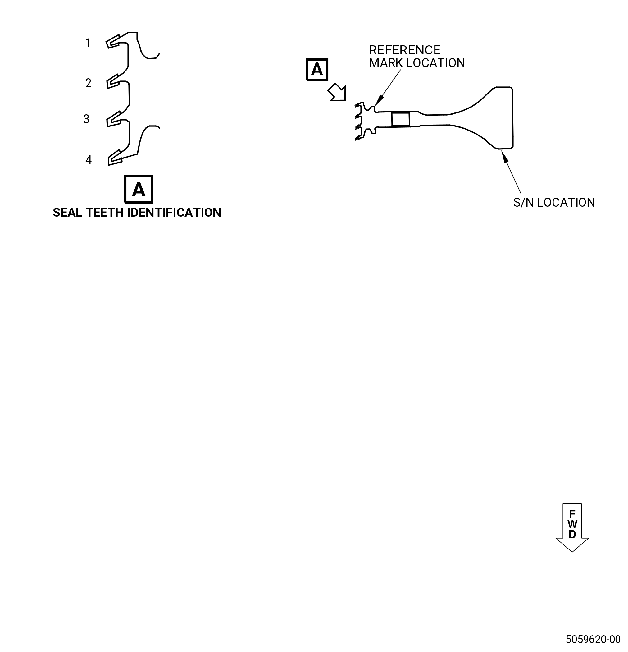
| A. | Make sure that the part number and the serial number of the CDP seal. Refer to Figure 201 and do as follows: |
| Subtask 72-00-31-350-002 |
| (1) | Put a reference mark on the aft side of the part close to the seal teeth that is radially in line with the slash symbol (/) in the serial number identification (S/N). |
| NOTE: |
|
| NOTE: |
|
| Subtask 72-00-31-220-081 |
| WARNING: |
|
| (2) | Perform a visual inspection of the seal teeth and mark on the part the location of any nicks, dents or other anomalies, which may prevent the inspection or cause an indication during inspection. Any damage or condition that prevents the probe from moving across the tooth must be inspected with FPI by the engine manual. If necessary, lightly clean the areas using an approved solvent. |
| 5 . | Procedure. |
| Subtask 72-00-31-250-001 |
| A. | Do the initial equipment setup as follows: |
| (1) | Turn the eddy current instrument on. |
| (2) | Let the instrument warm up. Refer to manufacturer's recommendations or at least 10 minutes before the inspection. |
| (3) | Adjust the instrument to the initial settings listed in the table that follows: |
|
||||||||||||||||||||||||||||||||||||||||||||||||||||||||||||||||||||||||||||||||||||||||||||||||||||||||||||||||||||||||||
|
||||||||||||||||||||||||||||||||||||||||||||||||||||||||||||||||||||||||||||||||||||||||||||||||||||||||||||||||||||||||||||||||||||||
|
||||||||||||||||||||||||||||||||||||||||||||||||||||||||||||||||||||||||||||||||||||||||||||||||||||||||||||||||||||||||||||||||||||||
|
||||||||||||||||||||||||||||||||||||||||||||||||||||||||||||||||||||||||||||||||||||||||||||||||||||||||||||||||||||||||||||||||||||||||||||||||||||||||||||||||||||||||||||||||||||||||||||||||||||||||||||||||||||||||||||||||||||||||||||||||||||||||||
|
||||||||||||||||||||||||||||||||||||||||||||||||||||||||||||||||||||||||||||||||||||||||||||||||||||
|
||||||||||||||||||||||||||||||||||||||||||||||||||||||||||||||||||||||||||||||||||||||||||||||||||||||||||||||
|
|||||||||||||||||||||||||||||||||||||||||||||||||||||||||||||||||||||||||||||||||||||||||||||||||||||||
|
||||||||||||||||||||||||||||||||||||||||||||||||||||||||||||||||||||||||||||||||||||||||||||||||||||||||||||||||||||||||||||||||||||||||||||||||||
|
|||||||||||||||||||||||||||||||||||||||||||||||||||||||||||||||||||||||||||||||||||||||||||||||||||||||||||||||||||||||||||||||||||
|
||||||||||||||||||||||||||||||||||||||||||||||||||||||||||||||||||||||||||||||||||||||||||||||||||||||||||||||||||||||||||||||||||||||||||||
|
||||||||||||||||||||||||||||||||||||||||||||||||||||||||||||||||||||||||||||||||||||||||||||||||||||||||||||||||
| Subtask 72-00-31-820-001 |
| B. | Do the calibration of the system as follows: |
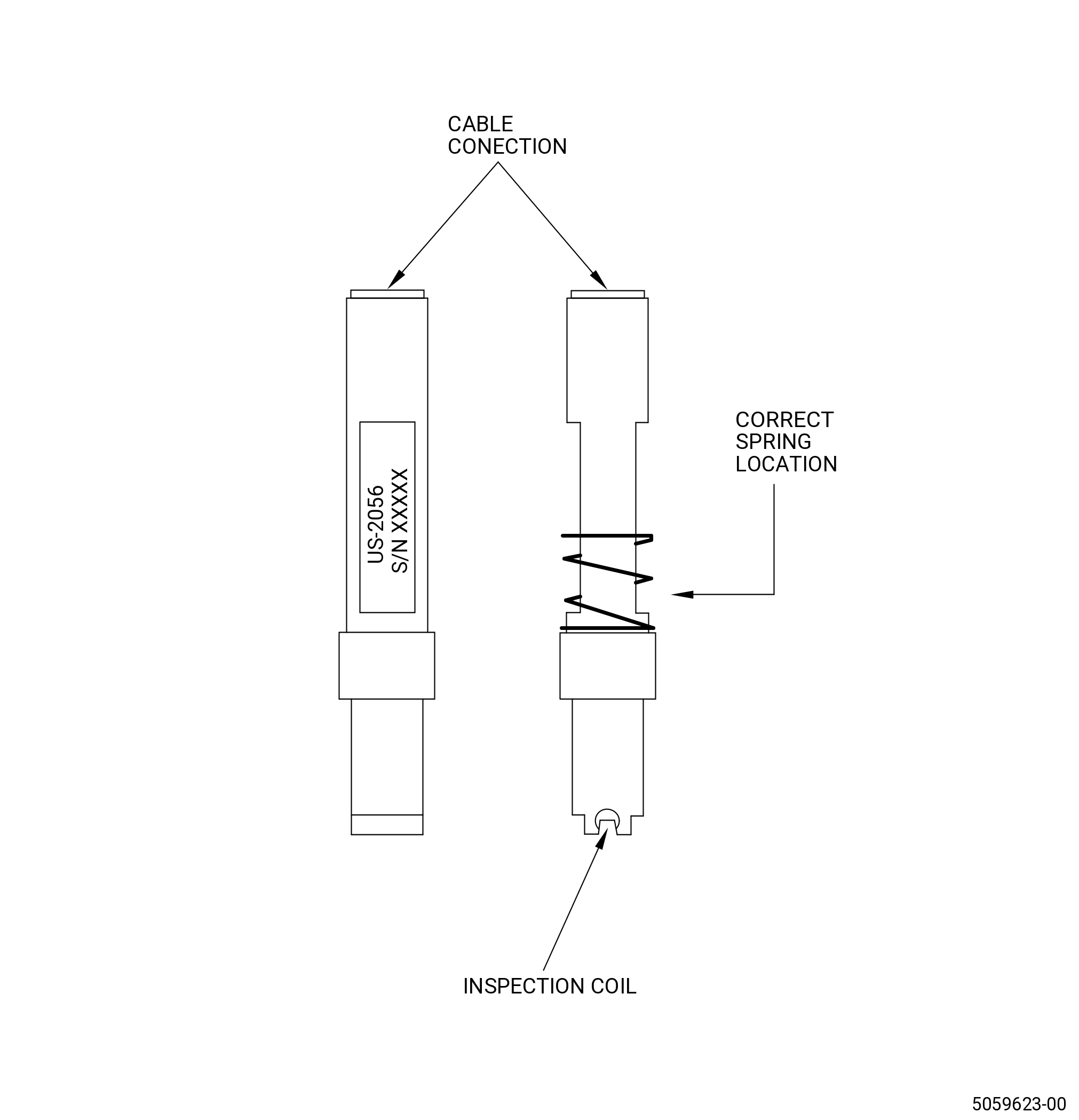
| (1) | Insert probe P/N: US-2056 into probe holder P/N: JO57138 for the following. |
| (a) | Make sure the spring is placed over the cable connection side of the probe and is resting on the large diameter of the probe body. Refer to Figure 204. |
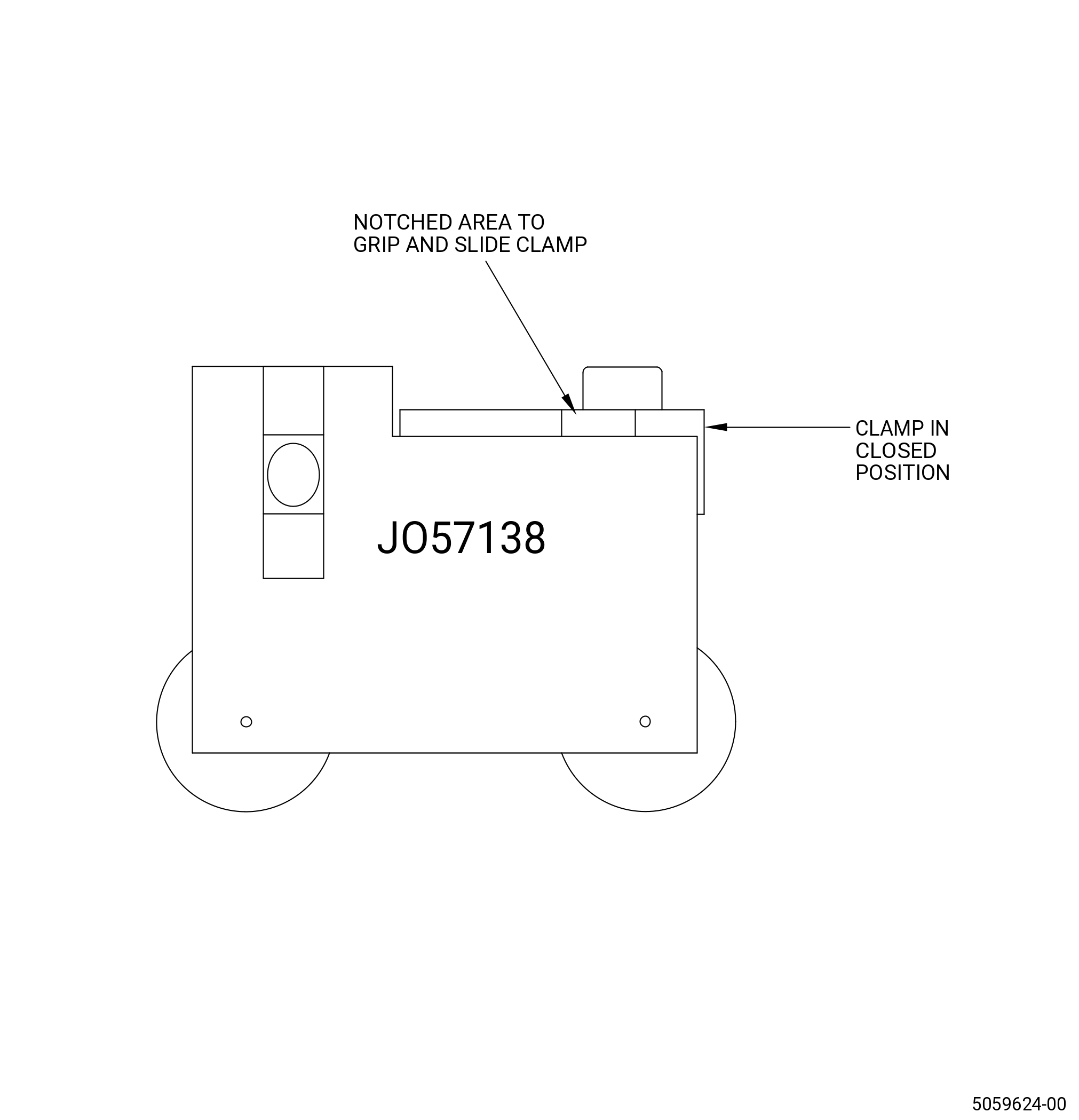
| (b) | Grasp the clamp on the probe holder by the two notched areas and slide it back, (open), until it stops. Refer to Figure 205. |
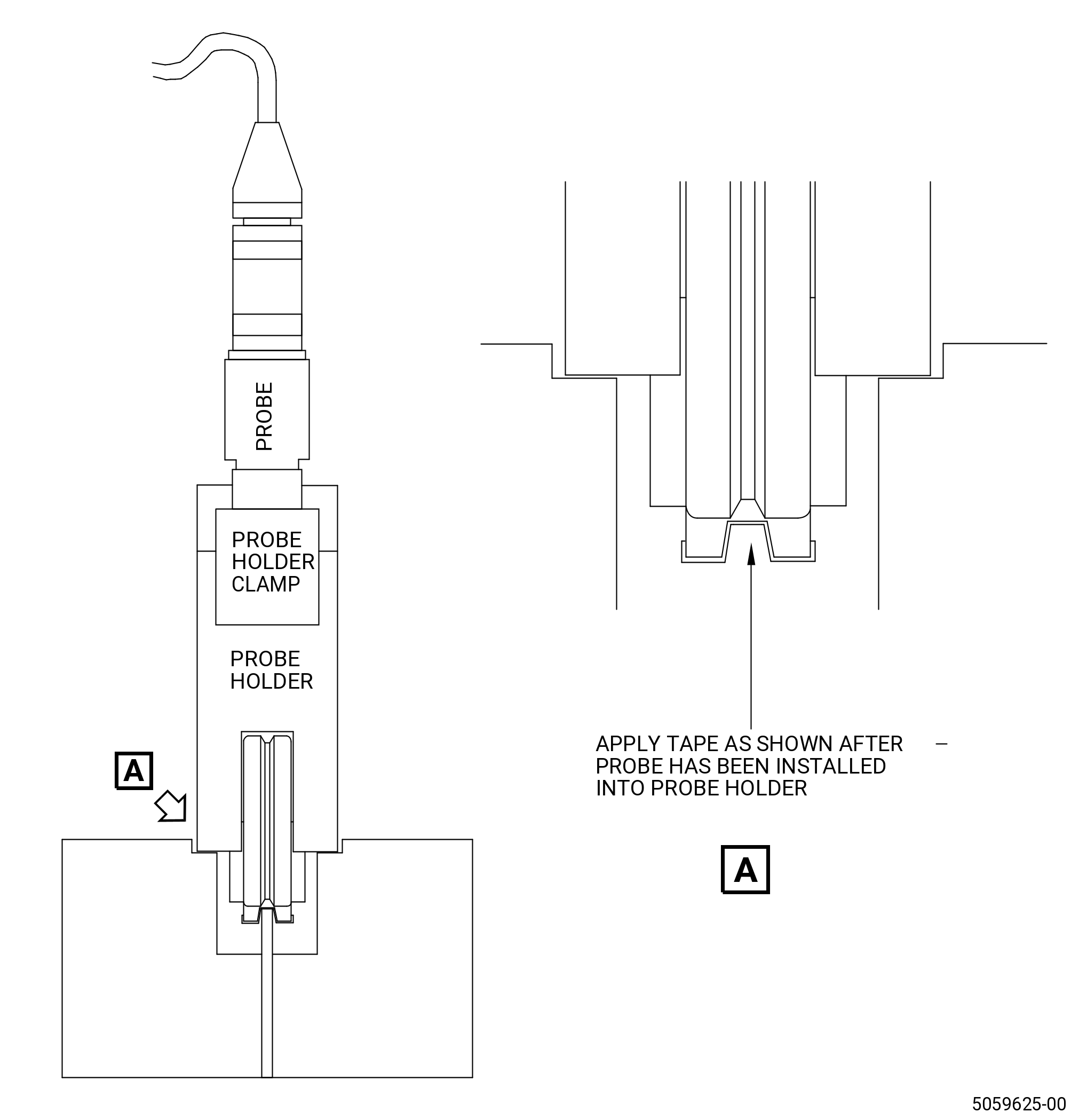
| (c) | Insert the probe, coil end first into the probe holder. Refer to Figure 206. |
| (d) | Make sure the flat sides of the probe body are parallel with the clamp slot and the spring is completely to the bottom of the probe holder counter bored hole. The clamp must glide easily over the top of the spring when closing to keep the probe locked into the holder. |
| (e) | Connect the inspection probe, P/N: US-2056, to the eddy current instrument with the probe cable, P/N: 94161. |
| (2) | Apply Teflon tape to the probe as follows: |
| (a) | Make sure the tape is correctly attached to the bottom of the groove in the probe tip. Refer to Figure 206. |
| (b) | An acceptable method to attach the tape into the groove is with the use of the calibration standard to push the tape into the bottom of the probe tip groove and swiping the probe along the standard. |
| (c) | Make sure that the tape does not inhibit movement of the probe inside the probe holder. |
| CAUTION: |
|
| NOTE: |
|
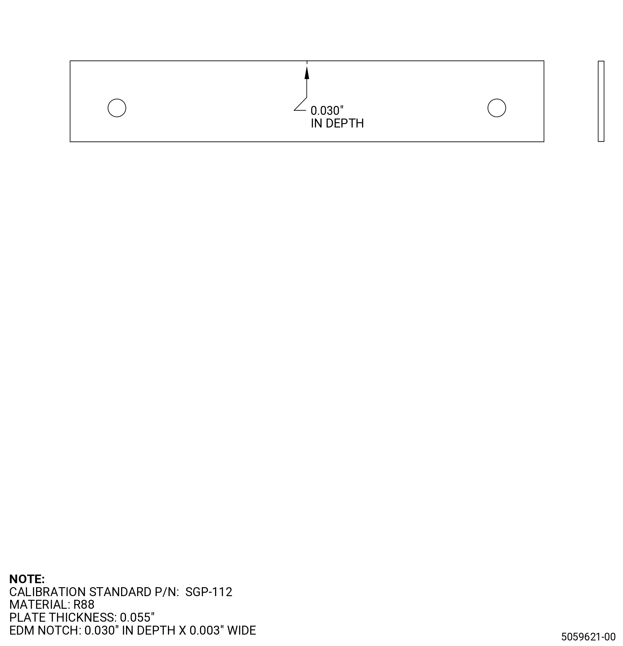
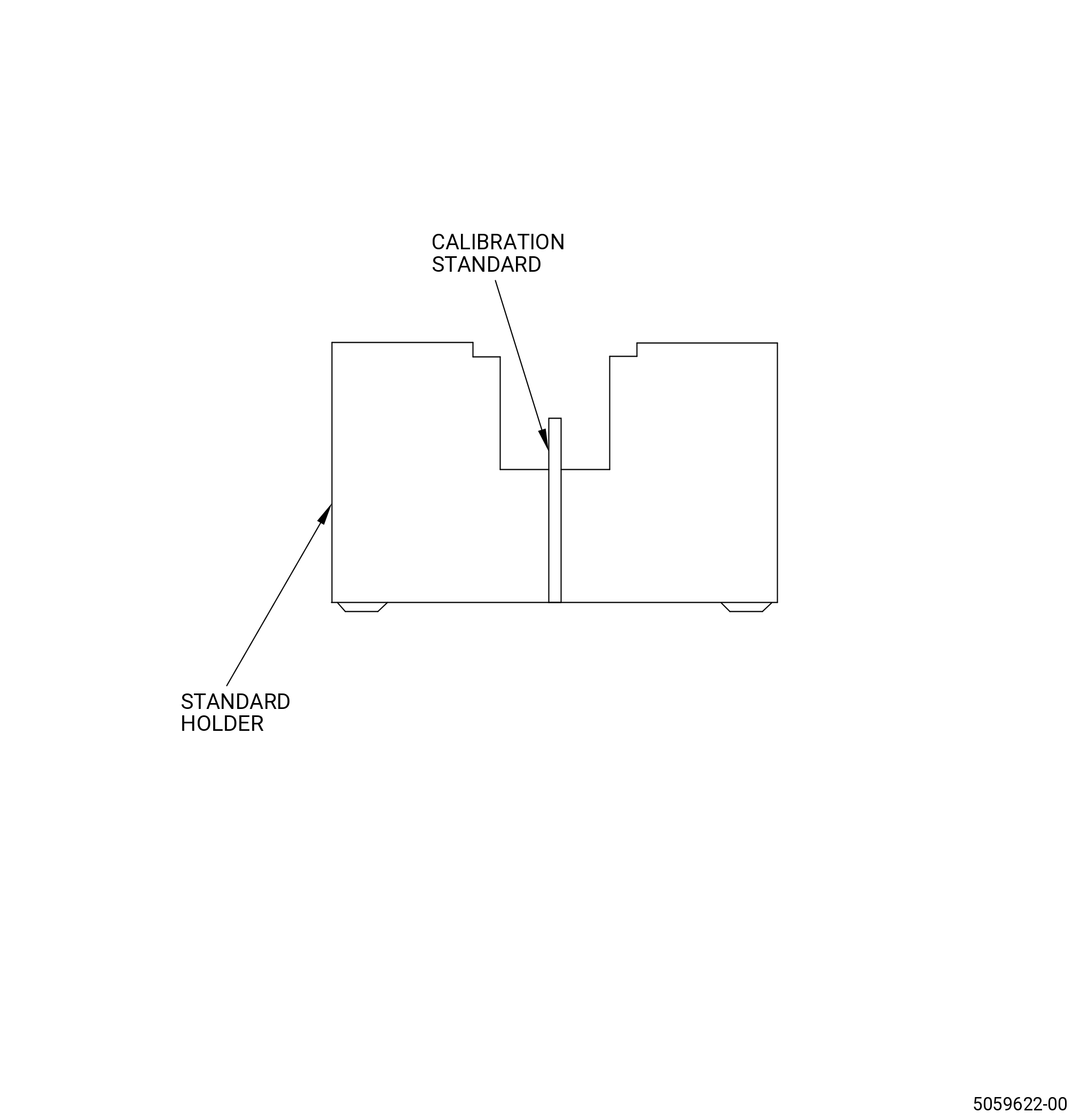
| (3) | Put the eddy current probe and probe holder on the calibration standard until the inspection coil is away from the electro discharge machining (EDM) notch. |
| (4) | Make sure the probe holder is seated flat on the calibration standard holder and the probe spring compresses up when set on the calibration standard. Refer to Figure 202, Figure 203, and Figure 206. |
| (5) | Null the eddy current instrument. |
| (6) | Slowly scan the probe across the EDM notch until the notch is detected and observe the response. Scan speed must be kept relatively slow, approximately 3.0 inches (76 mm) per second or less. |
| NOTE: |
|
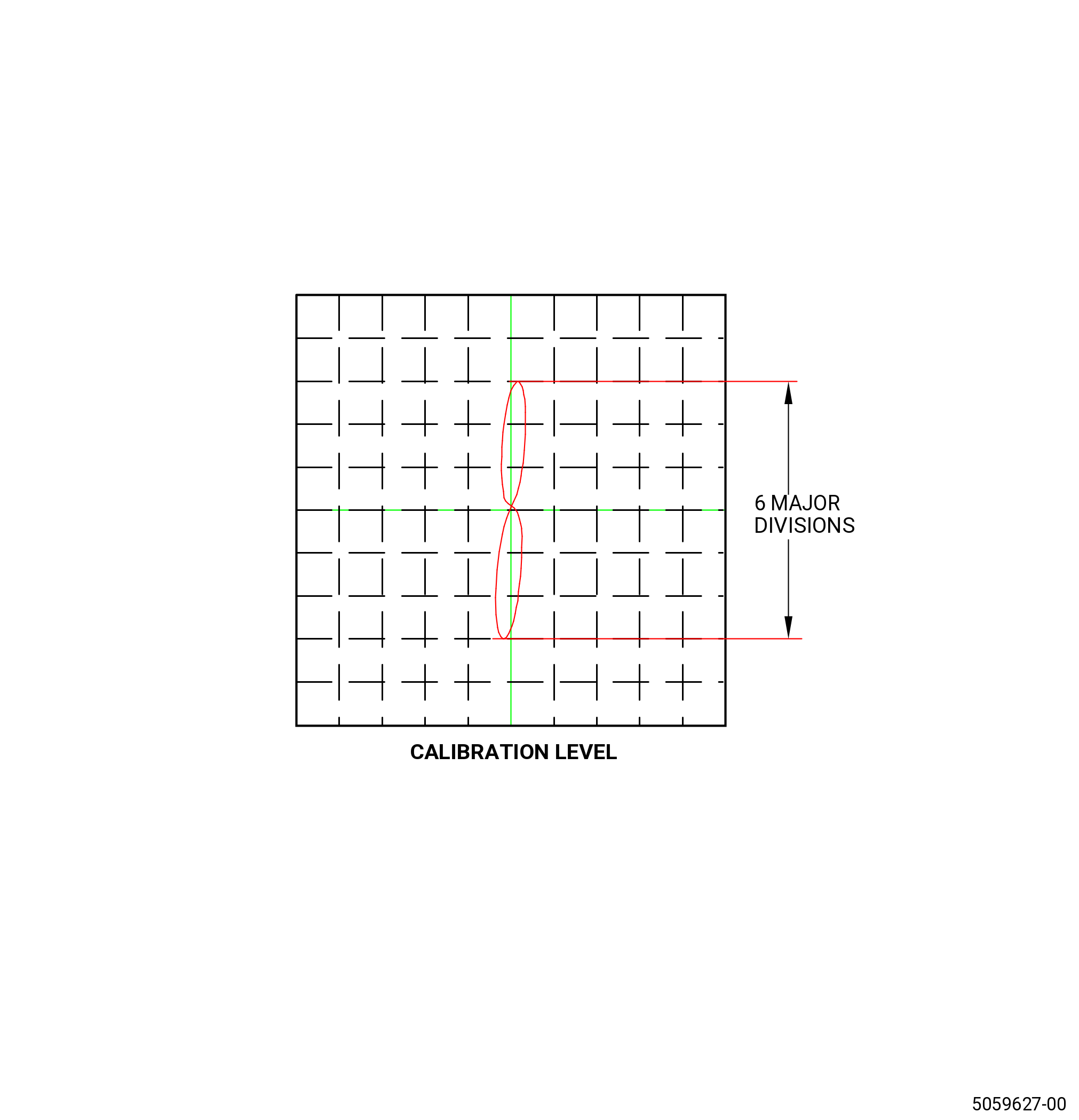
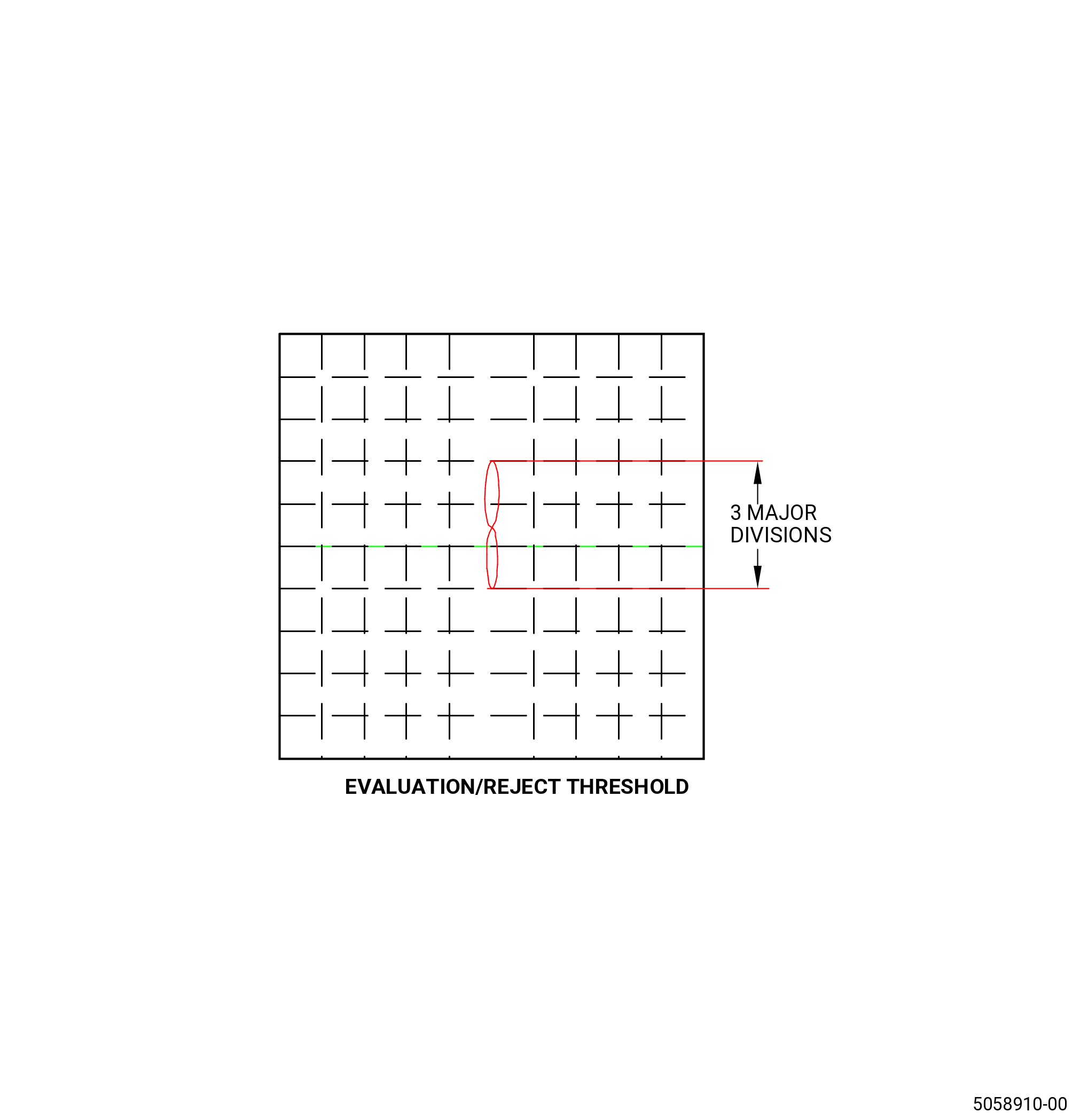
| (7) | While scanning back and forth across the EDM notch, adjust the instrument phase and gain control until the EDM notch response is vertical and 6 major divisions peak to peak. Refer to Figure 208. |
| (8) | Null the eddy current instrument again after you do instrument adjustments. Make sure that the probe coil is away from the EDM notch. |
| (9) | Scan the EDM notch again to make sure that the notch response is still vertical and at 6 major divisions peak to peak. |
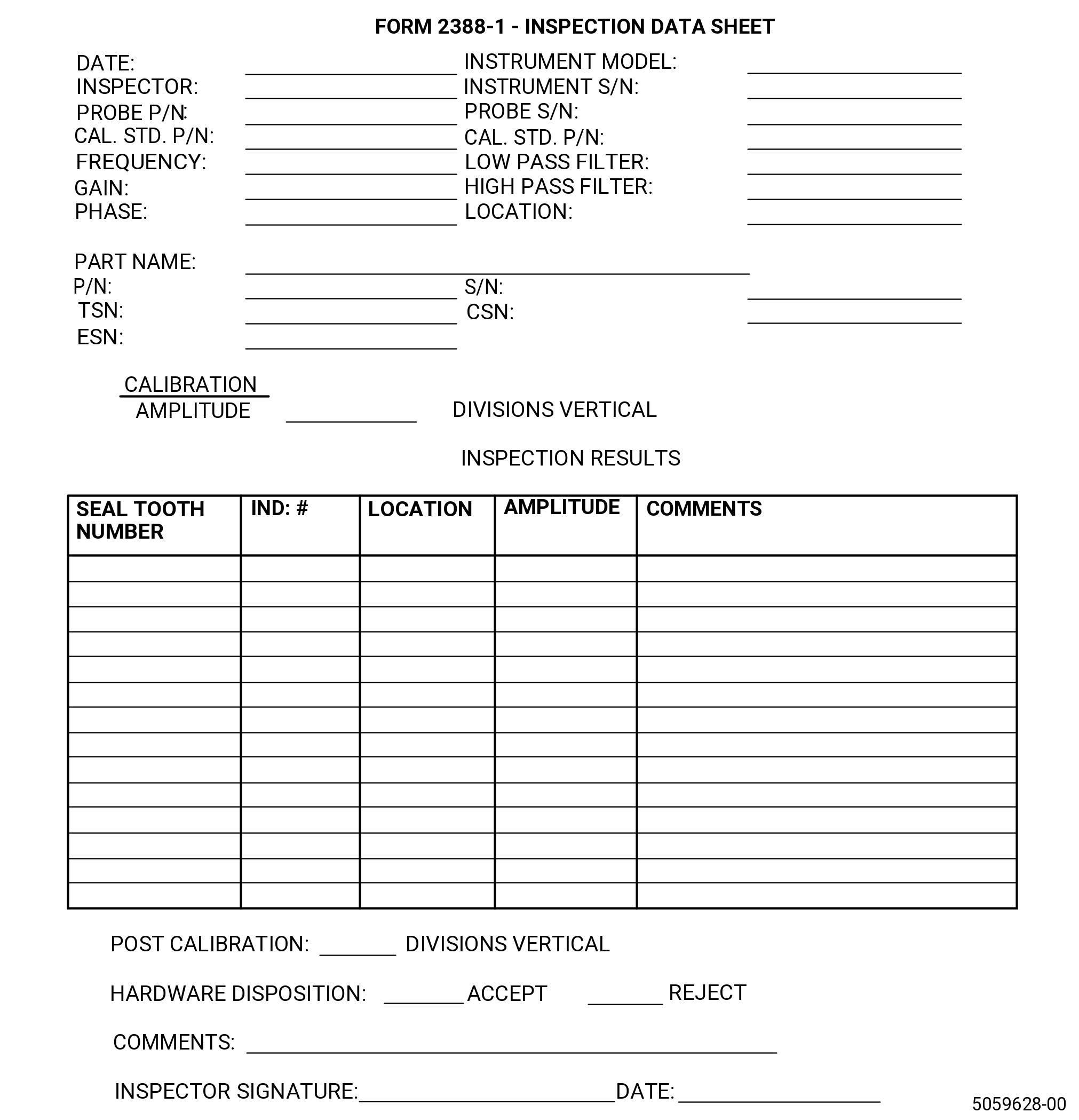
| (10) | Record all instrument settings and requested information on the appropriate inspection data sheet. Refer to Figure 210. |
| Subtask 72-00-31-250-002 |
| C. | Do the hardware inspection as follows: |
| NOTE: |
|
| NOTE: |
|
| (1) | Calibrate the equipment. Refer to Subtask 72-00-31-820-001 (paragraph 5.B). |
| Subtask 72-00-31-250-003 |
| CAUTION: |
|
| (2) | Start at the previously marked reference point (S/N). Refer to Subtask 72-00-31-350-002 (paragraph 4.A.(1)). |
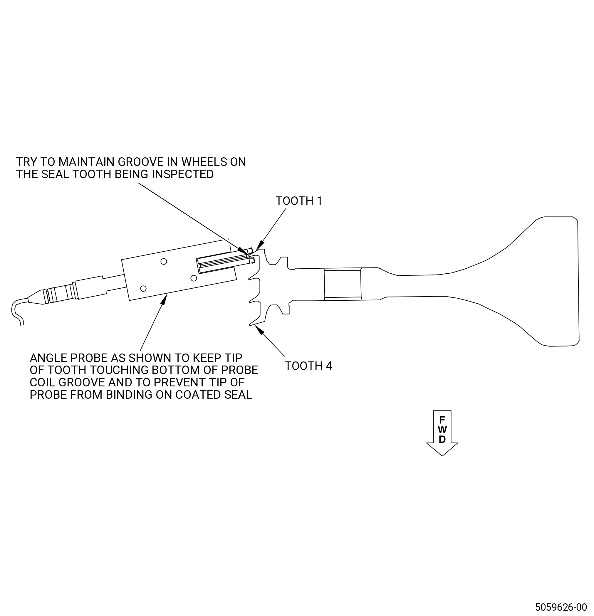
| (3) | Put the eddy current probe on the number one seal tooth. Refer to Figure 201. |
| (4) | Maintain the probe at an angle similar to the angle of the seal teeth. The bubble level is not used for this inspection. Refer to Figure 207. |
| (5) | When you put the coil over the seal tooth, make sure the spring applies pressure to the probe and the seal tooth is riding in the groove of both the probe and the probe holder wheels. Refer to Figure 207. |
| (6) | Try to keep the wheels of the probe holder on the seal teeth so the probe is not restricted while performing the inspection around the seal teeth. |
| (7) | With the probe properly seated over the seal tooth, null the eddy current instrument. |
| (8) | Scan the circumference of the part overlapping the start and stop position to make sure a 360 degree coverage of the entire seal tooth. Scan speed must be kept relatively slow, approximately 3.0 inches (76 mm) per second or less. |
| NOTE: |
|
| (9) | Monitor the instrument display for any indication equal to or exceeding 3.0 major divisions, regardless of scan direction. |
| (10) | For any indications equal to or exceeding 3.0 major divisions, perform an evaluation as described in the evaluation section of this document. Record the indication amplitude on the inspection data sheet. Refer to Figure 210. |
| Subtask 72-00-31-250-004 |
| (11) | It is recommended that the tape be replaced after every tooth is inspected or as needed. A calibration check must be performed before and after every tape change to make sure that the calibration sensitivity has not changed. Refer to Subtask 72-00-31-210-001 (paragraph 5.D.) for a calibration check. |
| Subtask 72-00-31-250-005 |
| (12) | Do Subtask 72-00-31-250-003 (paragraph 5.C.(2)) thru Subtask 72-00-31-250-004 (paragraph 5.C.(11)) again for the remaining seal teeth. |
| Subtask 72-00-31-210-001 |
| D. | Do a calibration check as follows: |
| (1) | Do a calibration check, if you are in the conditions that follow: |
| (a) | After each inspection. |
| (b) | The component is changed. |
| (c) | The operator is changed. |
| (d) | After loss of power. |
| (e) | When the operator suspects a change in the system. |
| (f) | Before and after every tape change. |
| (g) | At least once every hour. |
| (2) | Put the eddy current probe and probe holder on the calibration standard until the inspection coil is away from the EDM notch. |
| (3) | Make sure that the probe holder is setting flat on the calibration standard holder and that the probe spring is compressed when set on the standard. |
| (4) | Null the eddy current instrument. |
| (5) | Slowly scan the probe across the EDM notch of the calibration standard and observe the response. |
| NOTE: |
|
| (6) | If the calibration shows to be in a half division full screen height (FSH) (5.5 to 6.5) of the initial calibration again, the test was acceptable. |
| (7) | If the notch response is less than 5.5 divisions, the system must be calibrated again and all hardware inspected since the last acceptable calibration must be inspected again. |
| (8) | If the notch response is greater than 6.5 divisions, the system must be calibrated again prior to inspection of additional hardware and any rejected hardware must be inspected again. |
| Subtask 72-00-31-210-002 |
| E. | Do an evaluation of the indications as follows: |
| (1) | Indications that are equal or more than three major divisions must be evaluated as follows: |
| (a) | Make sure that the calibration notch response is still at 6 major divisions in amplitude. |
| (b) | Do a visual inspection of the seal tooth for any blends, nicks, dents, or other anomalies. Record the results on Figure 210. |
| WARNING: |
|
| CAUTION: |
|
| (c) | If necessary, lightly clean the surface in question with C04-003 acetone or C04-035 isopropyl alcohol. |
| (d) | If the suspect signal remains but is reduced in amplitude repeat the cleaning process as required to reduce the amplitude to an acceptable level. |
| (e) | If cleaning fails to reduce the indication to acceptable amplitude (below 3.0 major divisions), document the indications on the inspection data sheet. Refer to Figure 210. |
| (f) | Reposition the eddy current probe over the suspect area of the seal tooth and scan again several times to make sure that the previously observed indication can be repeated. If the calibration is correct and the indication is repeatable, the indication must be considered valid. |
| (g) | If the indication is not repeatable or less than (3.0 major divisions), the indication is not valid and must be considered acceptable. |
| Subtask 72-00-31-280-001 |
| F. | Disposition criteria. |
| (1) | Any seal tooth indications that are equal or exceed 3 major divisions, must be considered rejected by this procedure. |
| (2) | If there is no obvious reason for a rejectable eddy current indication, mark and record the location of the seal tooth indication on Figure 210 and continue to process the part to perform the FPI of the seal teeth by the engine manual. FPI must be the only inspection used to determine the serviceability of the part once the coating has been removed. |
| (3) | If the rejectable eddy current indication appears to be from visual condition (damaged tooth), mark and record the location of the seal tooth indication on Figure 210 and continue to process the part to perform FPI of the seal teeth by the engine manual. FPI must be the only inspection used to determine the serviceability of the part once the coating has been removed. |
| Subtask 72-00-31-280-002 |
| G. | As a minimum, record all requested information on the inspection data sheet and forward to the local GE Aviation Product Support Engineering representative. |