| GENX-1B CLEANING,INSPECTION,AND REPAIR MANUAL | Dated: 11/30/2023 | |
| CIR 72-00-40 , SPECIAL PROCEDURES 001 | ||
| COMBUSTOR DIFFUSER ASSEMBLY - SPECIAL PROCEDURE - CDN CASE FUEL NOZZLE PAD BROKEN BOLT REMOVAL | ||
| GENX-1B CLEANING,INSPECTION,AND REPAIR MANUAL | Dated: 11/30/2023 | |
| CIR 72-00-40 , SPECIAL PROCEDURES 001 | ||
| COMBUSTOR DIFFUSER ASSEMBLY - SPECIAL PROCEDURE - CDN CASE FUEL NOZZLE PAD BROKEN BOLT REMOVAL | ||
| * * * FOR ALL |
| TASK 72-00-40-800-801 |
| 1 . | CDN Case Fuel Nozzle Pad Broken Bolt Removal. |
| NOTE: | 72-00-40, SPECIAL PROCEDURES 001 can be used to remove broken bolts from both key lock and ring lock insert design cases. Refer to Case #01984523. |
| A. | This procedure provides instructions for the removal of broken bolts from the combustor case fuel nozzle pad. Refer to Figure 201. |
| 2 . | Tools, Equipment, and Materials. |
| NOTE: |
|
| A. | Tools and Equipment. |
| (1) | Special Tools. |
|
| (2) | Standard Tools and Equipment. None. |
| (3) | Locally Manufactured Tools. None. |
| B. | Consumable Materials. None. |
| C. | Referenced Procedures. |
|
| D. | Expendable Parts. None. |
| E. | SPD Information. None. |
| F. | Special Solutions. None. |
| G. | Test Specimens. None. |
| 3 . | Dimensional Information. |
| Subtask 72-00-40-220-157 |
| A. | Refer to TASK 72-41-01-200-801 (72-41-01, INSPECTION 001). |
| 4 . | Setup Information. |
| None. |
| 5 . | Procedure. |
| Subtask 72-00-40-350-001 |
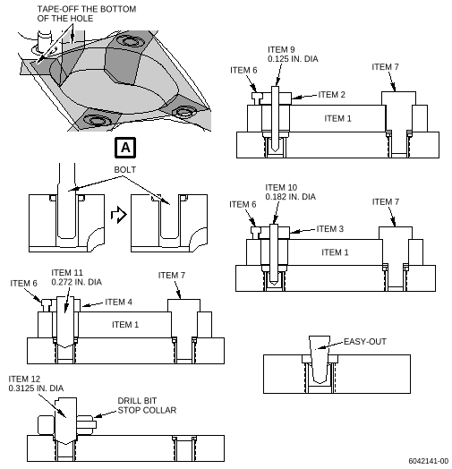
| A. | Remove the broken bolts from the combustor case fuel nozzle pads. Refer to Figure 201 and do as follows: |
| (1) | Tape-off the slot and the threaded holes of the combustion case. |
| (2) | Grind the broken engine bolt flush with the combustion case. |
| (3) | Safety the plate (item 1) on the fuel nozzle pad with three screws (item 7). |
| (4) | Insert the 0.272 bushing (item 4) over the broken engine bolt. |
| (5) | Safety the 0.272 bushing (item 4) with the lock screw (item 6). |
| (6) | Lubricate the tip of the bits to prevent overheating. |
| (7) | Drill the shank of the engine bolt to below the swage material with the 0.272 drill bit (item 11). |
| (8) | Remove the lock screw (item 6), the 0.272 bushing (item 4), the screws (item 7) and the plate (item 1). |
| (9) | Install the 0.3125 stop collar to a depth of 0.08-0.09 in. (2.0-2.3 mm) on the 0.3125 drill bit (item 12). |
| (10) | Use the 0.3125 drill bit (item 12) to break the swage between the insert and the locking ring. Remove locking ring. |
| (11) | Safety the plate (item 1) on the fuel nozzle pad using three screws (item 7). |
| (12) | Install the 0.125 bushing (item 2) above the damaged engine bolt. |
| (13) | Safety the 0.125 bushing (item 2) to the plate (item 1) with the lock screw (item 6). |
| (14) | Lubricate the tip of the bits to prevent overheating. |
| (15) | Drill the engine bolt with the 0.125 drill bit (item 9) deep enough to permit the use of easy-out tool. |
| NOTE: |
|
| (16) | Remove the 0.125 bushing (item 2) and install the 0.182 bushing (item 3) above the damaged engine bolt. |
| (17) | Safety the 0.182 bushing (item 3) with the lock screw (item 6). |
| (18) | Drill the engine bolt with the 0.182 drill bit (item 10) deep enough to permit the use of easy out tool. |
| NOTE: |
|
| (19) | Remove the lock screw (item 6), 0.182 bushing (item 3), screws (item 7), and the plate (item 1). |
| (20) | Use an easy-out to remove the engine bolt. |
| (21) | Clean and store the tool parts in the container. |