| GENX-1B CLEANING,INSPECTION,AND REPAIR MANUAL | Dated: 09/29/2023 | |
| CIR 72-30-01 , REPAIR 003 | ||
| HIGH PRESSURE COMPRESSOR STATOR EXTENSION CASE - REPAIR - REPLACEMENT OF KEY-LOCKED INSERTS | ||
| GENX-1B CLEANING,INSPECTION,AND REPAIR MANUAL | Dated: 09/29/2023 | |
| CIR 72-30-01 , REPAIR 003 | ||
| HIGH PRESSURE COMPRESSOR STATOR EXTENSION CASE - REPAIR - REPLACEMENT OF KEY-LOCKED INSERTS | ||
| * * * FOR ALL |
| TASK 72-30-01-300-804 |
| 1 . | Replacement of Key-Locked Inserts. |
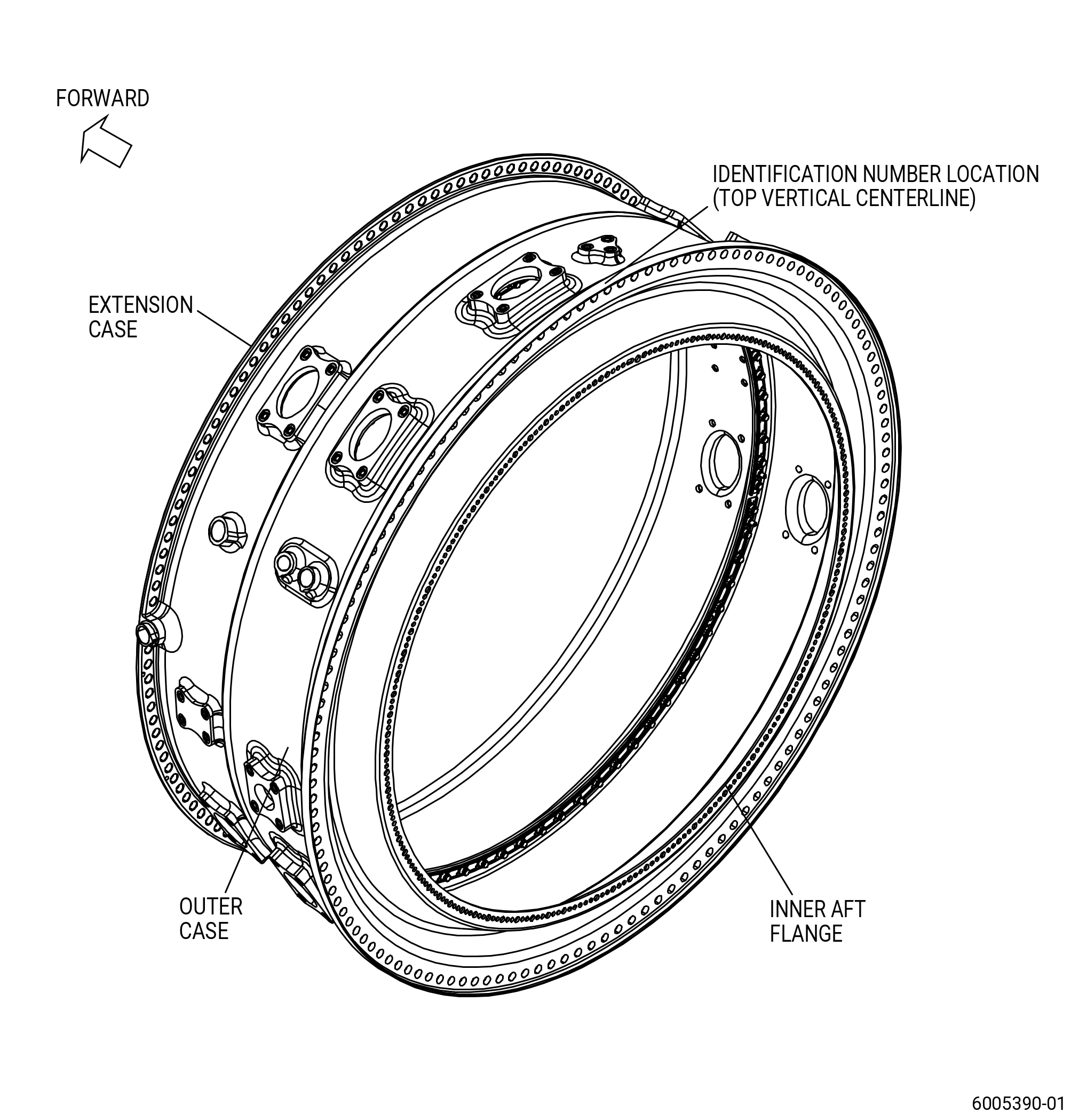
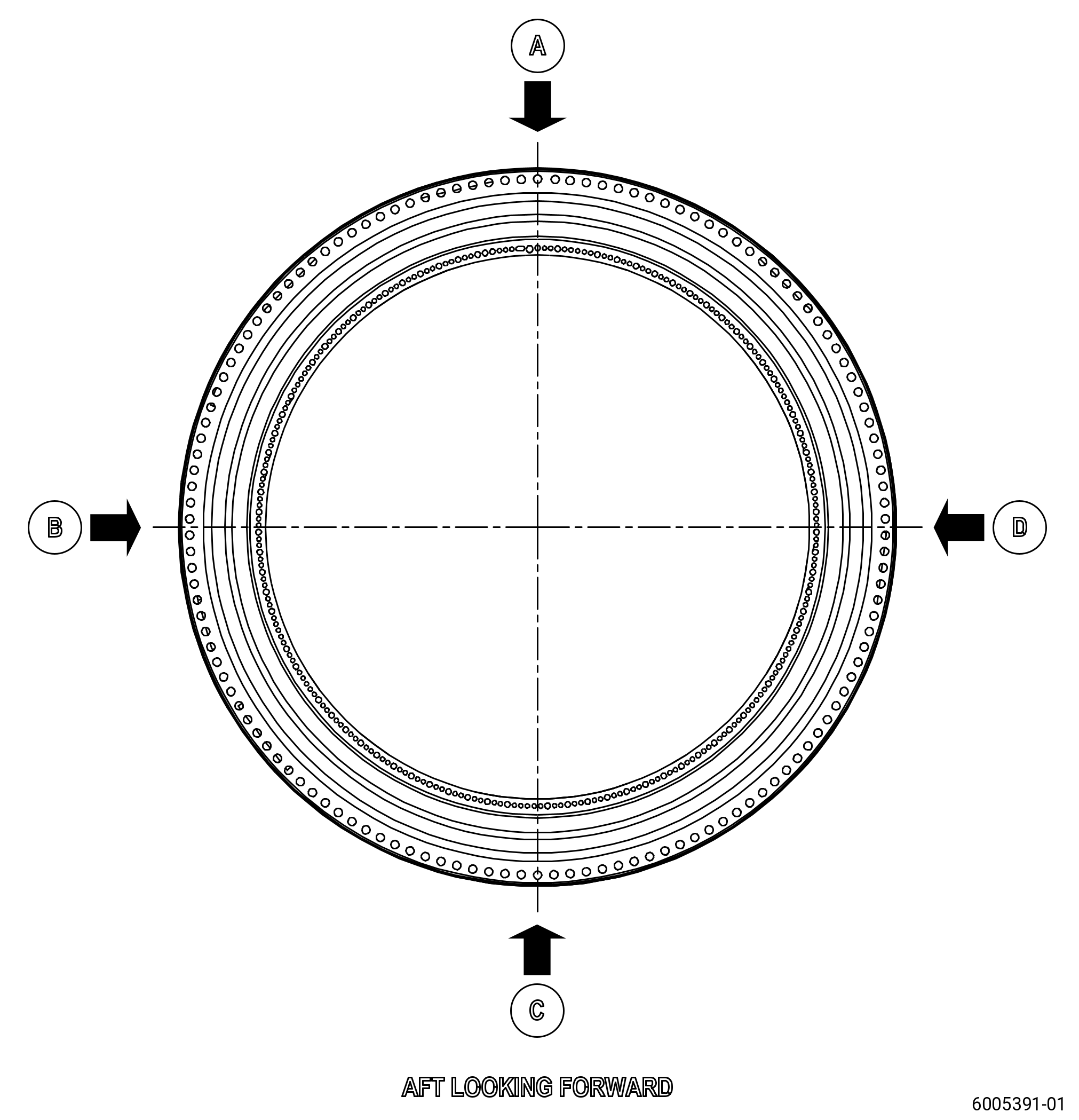
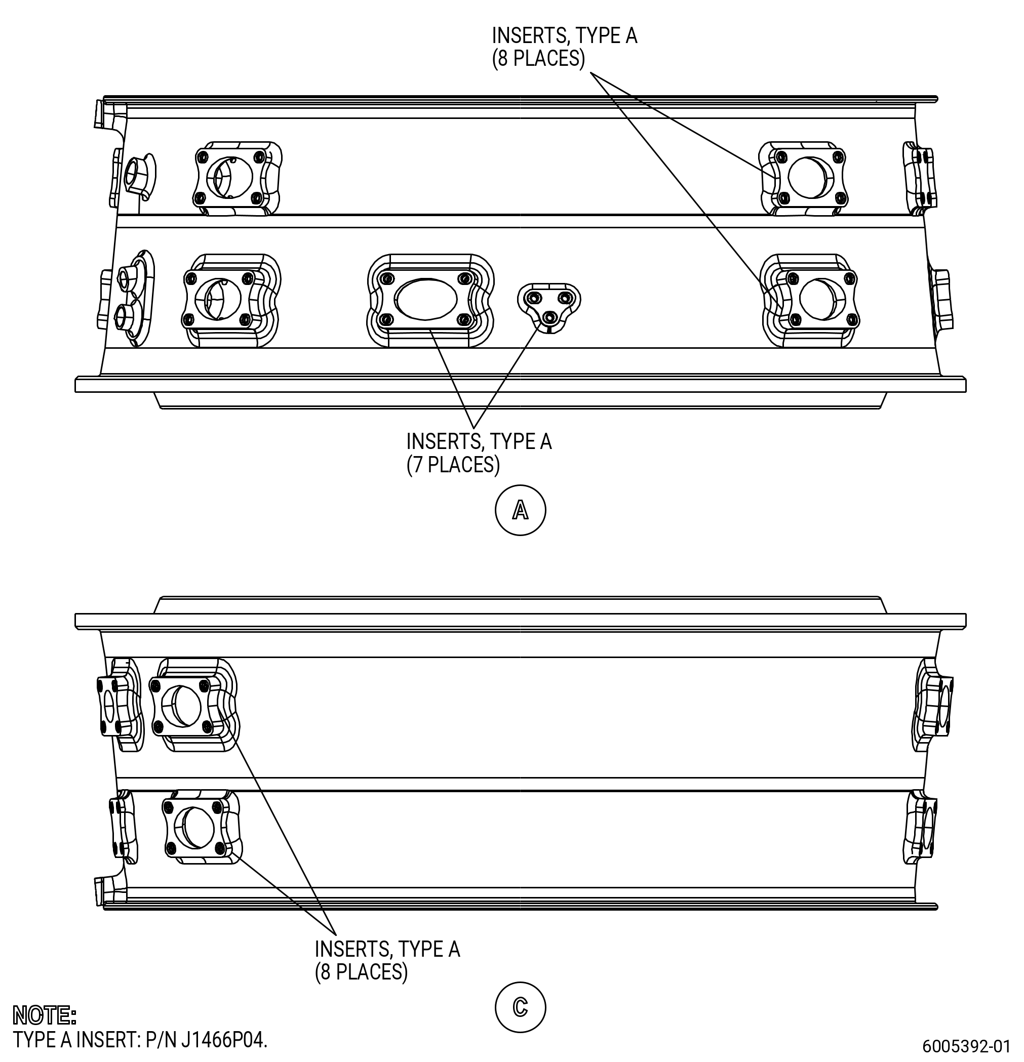
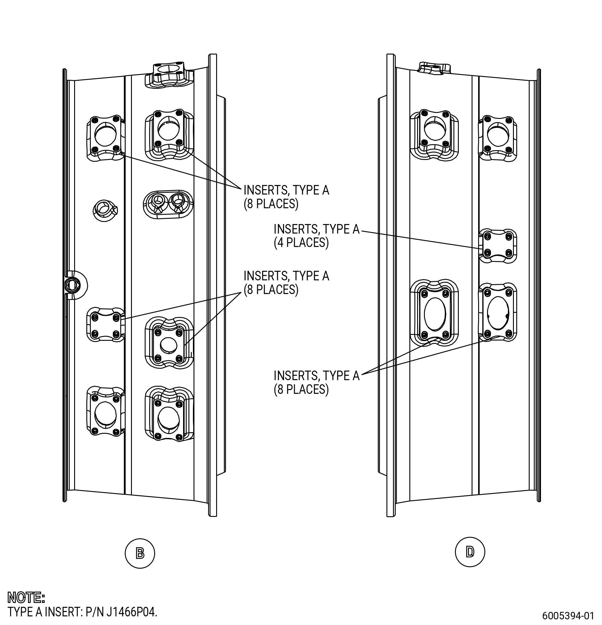
| A. | This procedure gives instructions to repair the high pressure compressor stator extension case (extension case) by replacing the damaged key-locked inserts. Refer to Figure 901. |
| B. | The following maximum repairable limits apply to this repair: |
| NOTE: |
|
| C. | The subsequent table gives a list of the part numbers that are applicable to this procedure. All part numbers are applicable to all paragraphs unless specified differently. |
|
|||||||||||||||||||||||
| D. | Proprietary/Complex Process Statement. |
| (1) | None. |
| 2 . | Tools, Equipment, and Materials. |
| NOTE: |
|
| A. | Tools and Equipment. |
| (1) | Special Tools. None. |
| (2) | Standard Tools and Equipment. None. |
| (3) | Locally Manufactured Tools. None. |
| B. | Consumable Materials. None. |
| C. | Referenced Procedures. |
|
| D. | Expendable Parts. None. |
| E. | SPD Information. |
| (1) | Spares Supplied. |
|
| (2) | Protected Spares. None. |
| (3) | Locally Manufactured Spares. None. |
| F. | Special Solutions. None. |
| G. | Test Specimens. None. |
| 3 . | Dimensional Information. |
| None. |
| 4 . | Setup Information. |
| None. |
| 5 . | Procedure. |
| Subtask 72-30-01-160-006 |
| A. | If necessary, clean the extension case. Refer to TASK 72-30-01-100-801 (72-30-01, CLEANING 001). |
| Subtask 72-30-01-350-026 |
| B. | Remove the damaged key-locked inserts from the extension case. Refer to TASK 70-48-11-350-014 (INSTALLATION OF KEY-LOCKED INSERTS) and Figure 902. |
| Subtask 72-30-01-350-027 |
| C. | Install the new key-locked inserts in the extension case. Refer to TASK 70-48-11-350-014 (INSTALLATION OF KEY-LOCKED INSERTS), Figure 901, Figure 902, and as follows: |
| (1) | Install the new inserts (J1466P04 ) in the extension case. |