| GENX-1B CLEANING,INSPECTION,AND REPAIR MANUAL | Dated: 04/03/2024 | |
| CIR 72-53-41 , SPECIAL PROCEDURES 001 | ||
| HIGH PRESSURE TURBINE ROTOR STAGE 2 DISK - SPECIAL PROCEDURE - IMMERSION ULTRASONIC INSPECTION OF ENGINE RUN HARDWARE | ||
| GENX-1B CLEANING,INSPECTION,AND REPAIR MANUAL | Dated: 04/03/2024 | |
| CIR 72-53-41 , SPECIAL PROCEDURES 001 | ||
| HIGH PRESSURE TURBINE ROTOR STAGE 2 DISK - SPECIAL PROCEDURE - IMMERSION ULTRASONIC INSPECTION OF ENGINE RUN HARDWARE | ||
| * * * FOR ALL |
| TASK 72-53-41-800-801 |
| 1 . | General. |
| A. | This procedure gives instructions to do a component level immersion ultrasonic inspection of the engine run high pressure turbine (HPT) rotor stage 2 disk (stage 2 disk) (01-130 , 72-53-00) (SIN 150B1) or (02-130 , 72-53-00) (SIN 150B1) or (02-130A , 72-53-00) (SIN 150B1) or (02-130B , 72-53-00) (SIN 150B1). |
| B. | Changes to this procedure or substitutions for the equipment could result in reduced ability to detect cracks. In specific cases where deviations are desired, the procedure and equipment must be evaluated by GE Aviation. |
| C. | Any reject indications observed during the accomplishment of the following inspection should be reported to Fleet Support at Aviation.Fleet.Support1@ge.com. Please include the following details: |
| • Part number and serial number |
| • Customer/Operator |
| • Time since new |
| • Cycles since new |
| • Time since overhaul |
| • Cycles since overhaul |
| • Indication size(s) |
| • Photos of the indication(s). |
| Alternatively, this information can be submitted as a Service Request (SR) via myGEAviation.com. |
| 2 . | Tools, Equipment, and Materials. |
| NOTE: |
|
| A. | Tools and Equipment. |
| (1) | Special Tools. None. |
| (2) | Standard Tools and Equipment. |
|
| NOTE: |
|
| (3) | Locally Manufactured Tools. None. |
| B. | Consumable Materials. None. |
| C. | Referenced Procedures. |
|
| D. | Expendable Parts. None. |
| 3 . | Specific Inspection Procedure. |
| Subtask 72-53-41-220-093 |
| A. | Do a pre-inspection part preparation/cleaning. Refer to TASK 70-32-85-270-801 (ENHANCED IMMERSION ULTRASONIC INSPECTION OF LIFE LIMITED HARDWARE). |
| NOTE: |
|
| Subtask 72-53-41-820-002 |
| B. | Do the equipment calibration. Refer to TASK 70-32-85-270-801 (ENHANCED IMMERSION ULTRASONIC INSPECTION OF LIFE LIMITED HARDWARE) and as follows: |
| (1) | Part material is Rene 88 or Rene 65 which require a correction factor for calibration. Refer to TASK 70-32-85-270-801 (ENHANCED IMMERSION ULTRASONIC INSPECTION OF LIFE LIMITED HARDWARE) and use the Inco 718 and Rene correction factor for both materials. |
| (2) | Refracted longitudinal calibration: |
| (a) | Install the TYPE B transducer for the refracted longitudinal wave calibration. |
| (b) | Calibrate the refracted 20 degree 2-inch water path longitudinal scans in accordance with TASK 70-32-85-270-801 (ENHANCED IMMERSION ULTRASONIC INSPECTION OF LIFE LIMITED HARDWARE). |
| (c) | Record all calibration data on the appropriate calibration form contained in TASK 70-32-85-270-801 (ENHANCED IMMERSION ULTRASONIC INSPECTION OF LIFE LIMITED HARDWARE). |
| (3) | Shear wave calibration: |
| (a) | Install the TYPE B transducer for the shear wave calibration. |
| (b) | Calibrate the 45 degree 6-inch water path surface focus, 2-inch water path sub-surface focus and 65 degree 6-inch water path scans in accordance with TASK 70-32-85-270-801 (ENHANCED IMMERSION ULTRASONIC INSPECTION OF LIFE LIMITED HARDWARE). |
| (c) | Record all calibration data on the appropriate calibration form contained in TASK 70-32-85-270-801 (ENHANCED IMMERSION ULTRASONIC INSPECTION OF LIFE LIMITED HARDWARE). |
| Subtask 72-53-41-270-002 |
| C. | Do the immersion ultrasonic inspection as follows: |
| (1) | Refracted longitudinal inspection 2-inch water path (TYPE B transducer): |
| (a) | Follow the calibration routines provided in TASK 70-32-85-270-801 (ENHANCED IMMERSION ULTRASONIC INSPECTION OF LIFE LIMITED HARDWARE). |
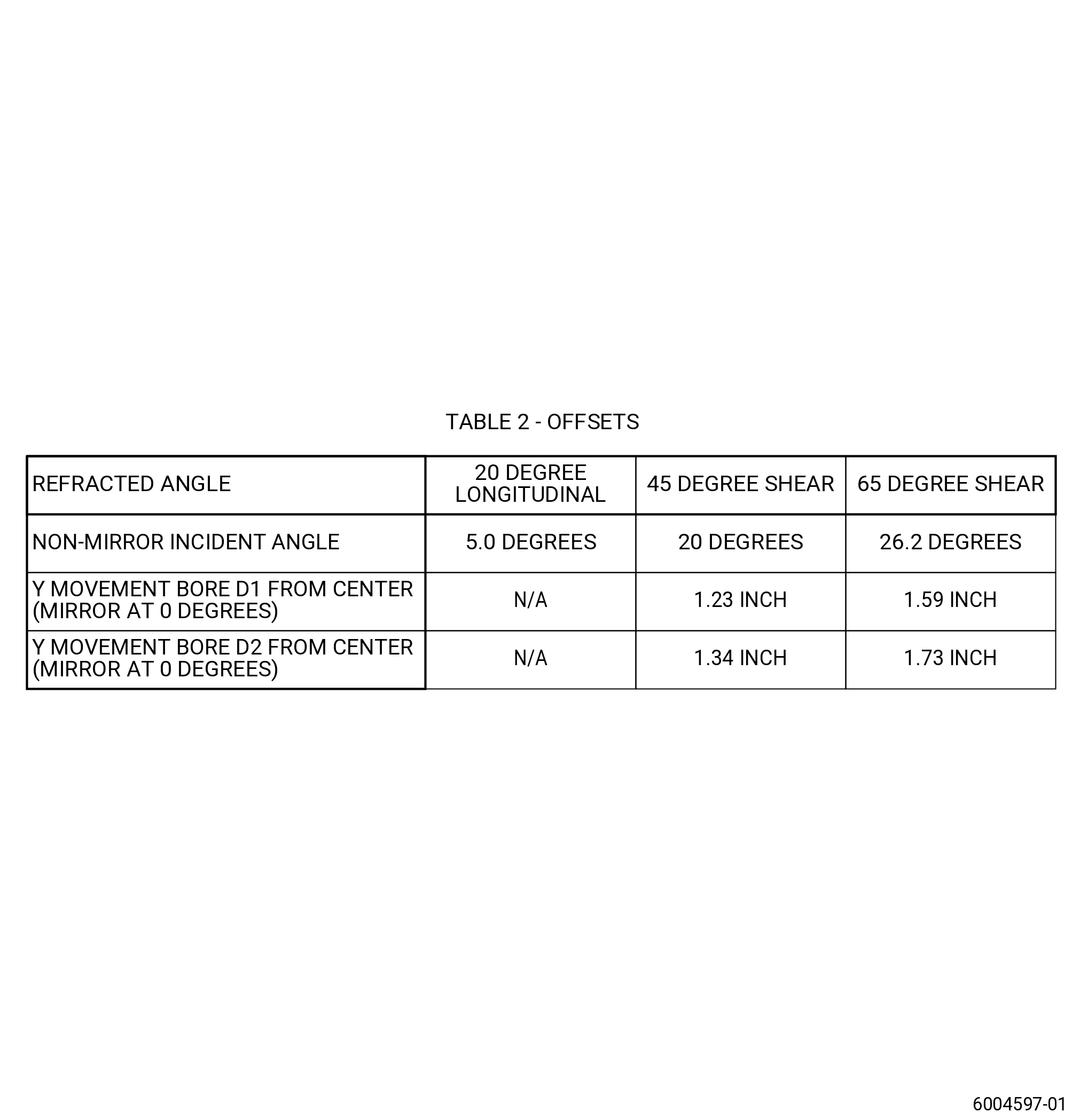
| (b) | Refer to Figure 202 for refracted longitudinal scan offsets. |
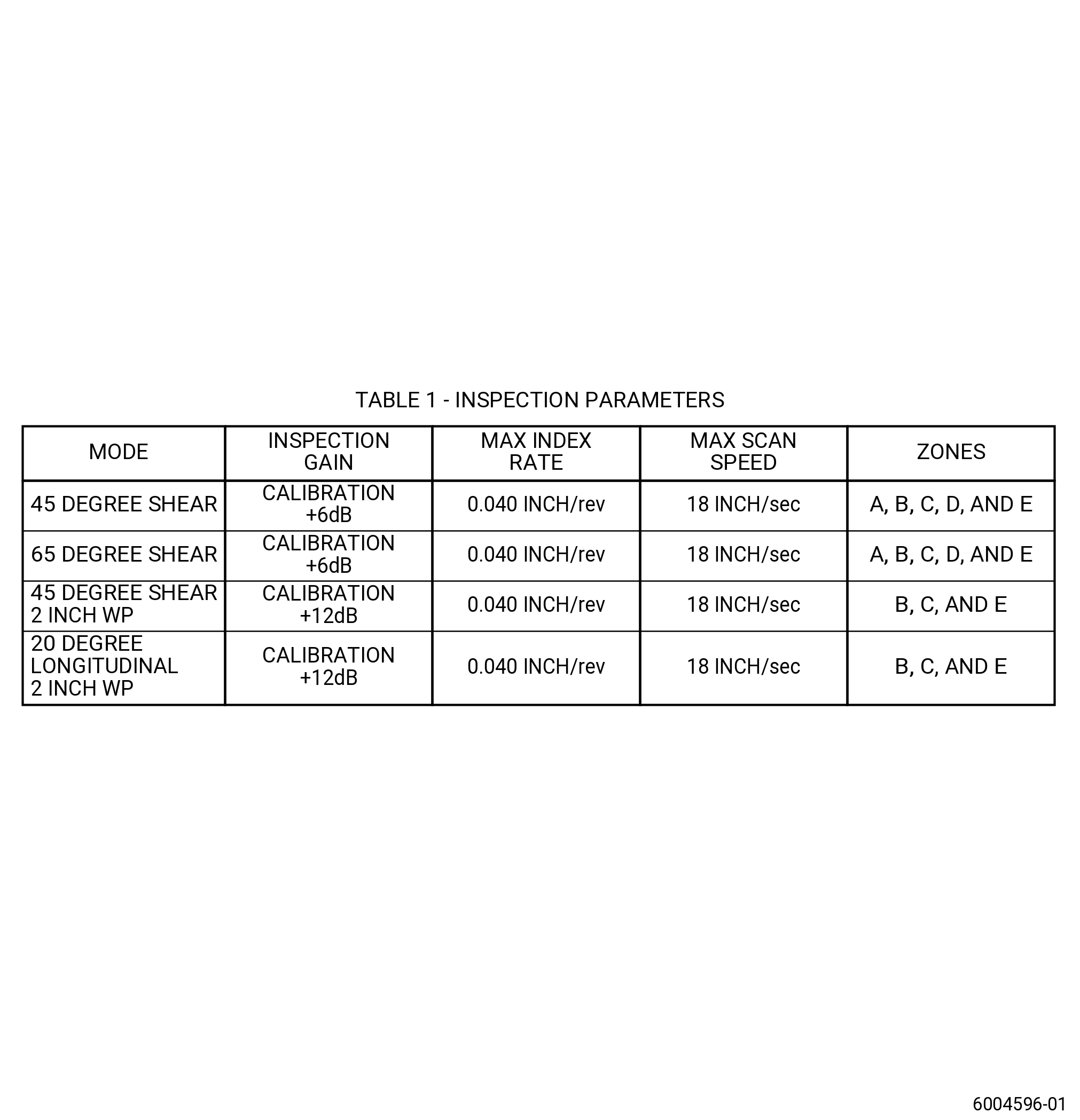
| (c) | Use the appropriate index rate, scan speed and gain identified for longitudinal inspection. Refer to Figure 201. |
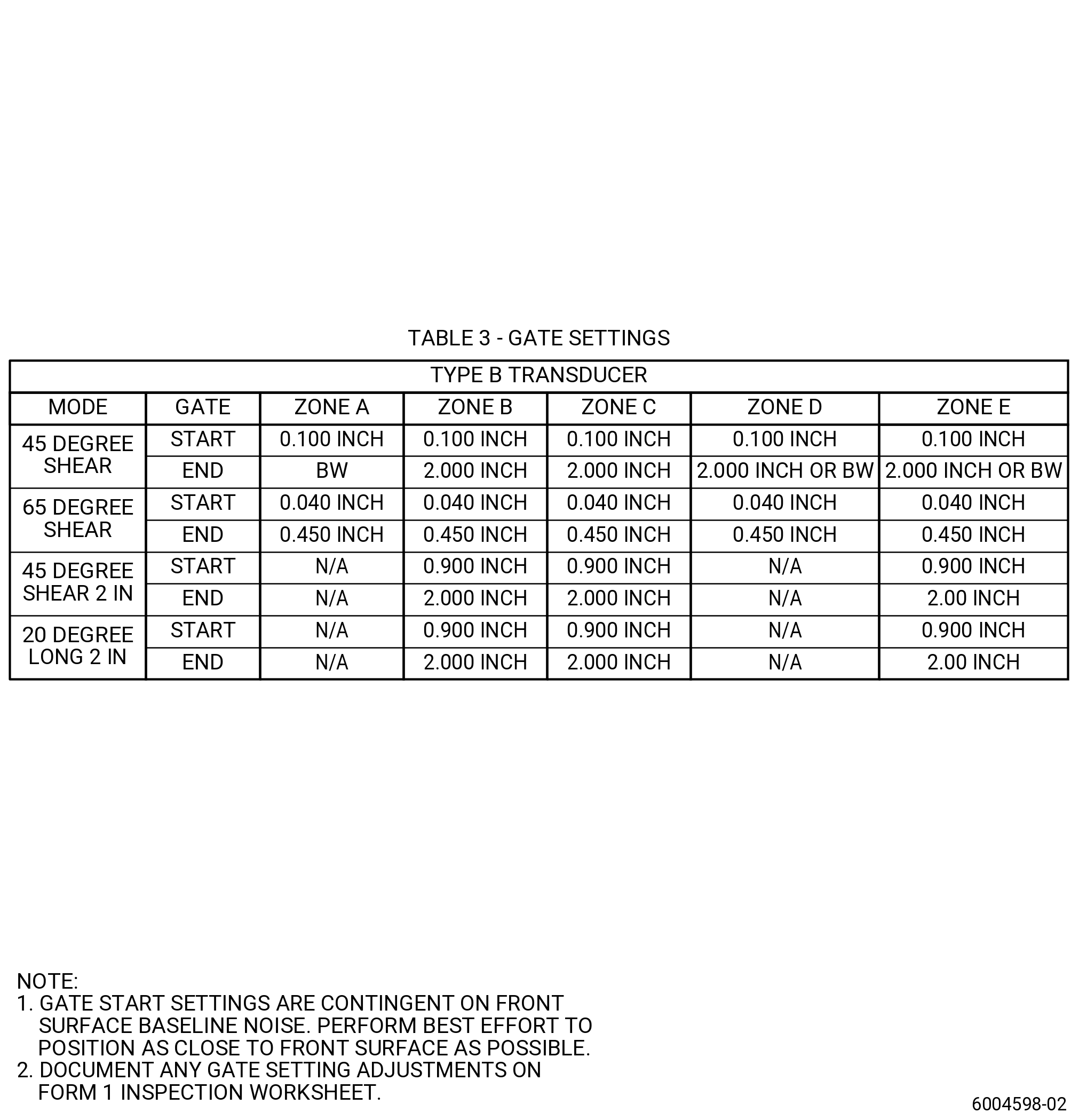
| (d) | Use TYPE B transducer gate settings. Refer to Figure 203. |
| (e) | It will be necessary to adjust the back of the gate to 2.00 inches (50.8 mm) or to the back wall if closer while the inspection is in process. The back-wall gate is not to be more than 2.00 inches (50.8 mm) while the scan takes place. |
| (f) | Scan hardware in accordance with Figure 207 and save all C-scan data for each scan. |
| (g) | Do a post calibration check, refer to TASK 70-32-85-270-801 (ENHANCED IMMERSION ULTRASONIC INSPECTION OF LIFE LIMITED HARDWARE). |
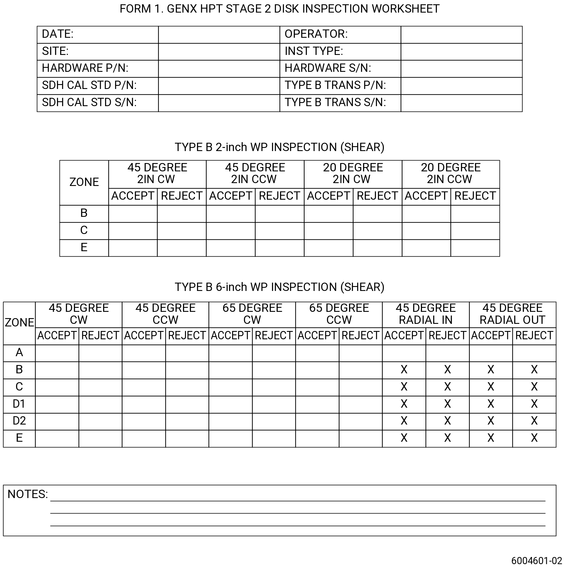
| (h) | Record the inspection results on Form 1 of this procedure. Refer to Figure 206. |
| (2) | Shear wave inspection 6-inch water path (TYPE B transducer): |
| (a) | Follow the calibration routines provided in TASK 70-32-85-270-801 (ENHANCED IMMERSION ULTRASONIC INSPECTION OF LIFE LIMITED HARDWARE). |
| (b) | Refer to Figure 202 for shear scan offsets. |
| (c) | Use the appropriate index rate, scan speed and gain. Refer to Figure 201. |
| (d) | Use TYPE B transducer gate settings. Refer to Figure 203. |
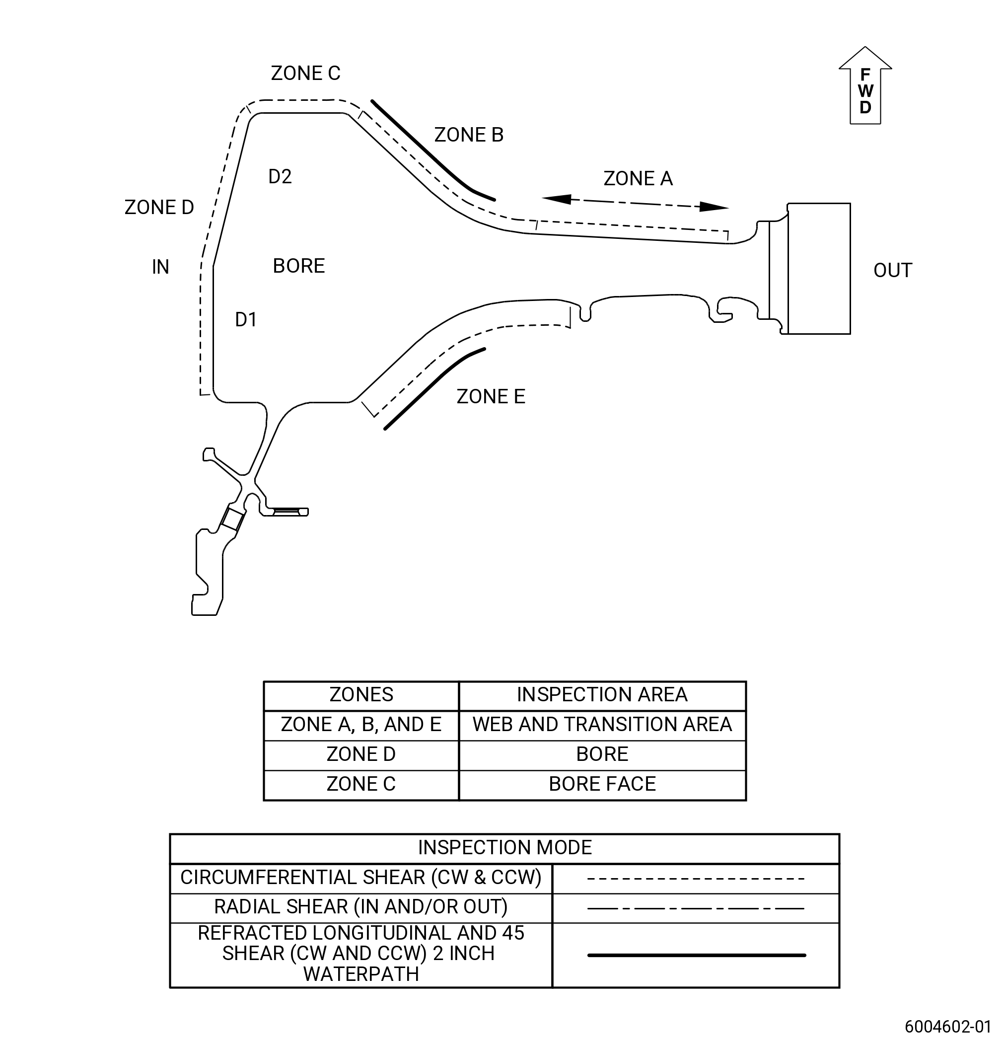
| (e) | Bore scans (Zone D): |
| 1 | Install the 3.50 inches (88.9 mm) or 5.0 inches (127 mm) ultrasonic inspection mirror such that the sound beam is normal to the inspection surface. |
| 2 | For 45 degree shear, it will be necessary to adjust the back of the gate to 2.00 inches (50.8 mm) or to the back-wall, if closer while the inspection is in process. |
| 3 | For 45 degree shear, the back-wall gate must not be more than 2.00 inches (50.8 mm) while the scan takes place. |
| (f) | Bore face, transition areas and web scans (Zones A, B, C and E): |
| 1 | Remove the mirror and scan the areas in accordance with the scan plans. Refer to Figure 207. |
| 2 | For 45 degree shear, it will be necessary to adjust the back of the gate to 2.00 inches (50.8 mm) or to the back-wall, if closer while the inspection is in process. |
| 3 | For 45 degree shear, the back-wall gate must not be more than 2.00 inches (50.8 mm) while the scan takes place. |
| (g) | Scan hardware in accordance with Figure 207 and save all C-scan data for each scan. |
| (h) | Do a post calibration check, refer to TASK 70-32-85-270-801 (ENHANCED IMMERSION ULTRASONIC INSPECTION OF LIFE LIMITED HARDWARE). |
| (i) | Record the inspection results on Form 1 of this procedure. Refer to Figure 206. |
| (3) | Shear Wave 2-inch water path scans (Type B transducer): |
| (a) | Follow the calibration routines as provided in TASK 70-32-85-270-801 (ENHANCED IMMERSION ULTRASONIC INSPECTION OF LIFE LIMITED HARDWARE). |
| (b) | For 45 degree shear 2-inch water path, it will be necessary to adjust the back of the gate to 2.00 inches (50.8 mm) or to the back wall if closer while the inspection is in process. |
| (c) | For 45 degree shear, the back-wall gate is not to be more than 2.00 inches (50.8 mm) while the scan takes place. |
| (d) | Scan hardware in accordance with Figure 207 and save all C-scan data for each scan. |
| (e) | Do a post calibration check. Refer to TASK 70-32-85-270-801 (ENHANCED IMMERSION ULTRASONIC INSPECTION OF LIFE LIMITED HARDWARE). |
| (f) | Record the inspection results on Form 1 of this procedure. Refer to Figure 206. |
| Subtask 72-53-41-220-094 |
| D. | Do an evaluation of the ultrasonic indications as follows: |
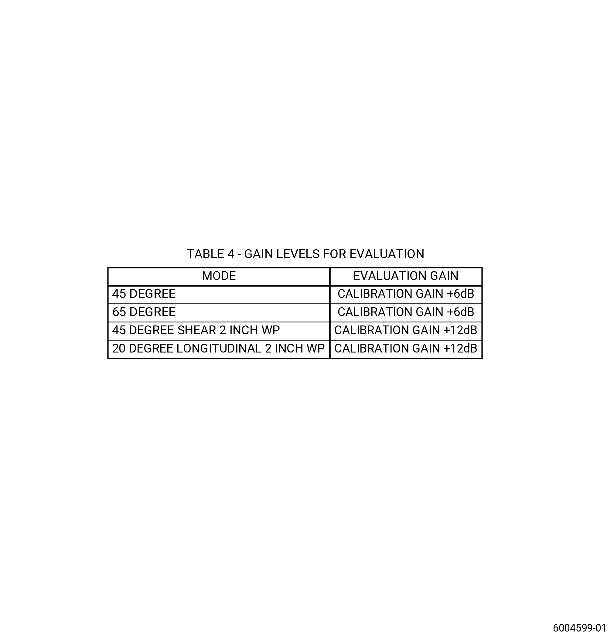
| (1) | All indications must be evaluated at the gain levels identified in Figure 204. |
| (a) | Deleted. |
| (b) | Deleted. |
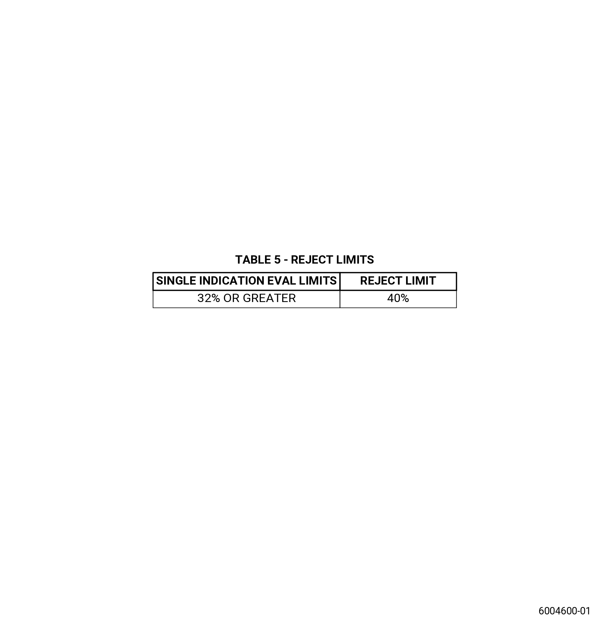
| (2) | Evaluate all repeatable discrete indications which are equal to or more than 32 percent full screen height (FSH). Refer to Figure 205 and do as follows: |
| (a) | Peak the response by translation and rotation only. |
| (b) | Reject all hardware for discrete indications which are repeatable and equal or more than 40 percent FSH. |
| (3) | Evaluate all repeatable discrete indications, regardless of amplitude, which are more than the following SNR ratios: |
| (a) | Peak the response by translation and rotation only. |
| (b) | Reject all hardware for discrete indications which are repeatable and greater than or equal to a 3.0 Signal to Noise ratio. |
| (c) | Indications detected in a minimum of two directions which are repeatable and are more than or equal to a 2.5 Signal to Noise ratio must be rejected. In addition, the indication depth must be the same at both directions in plus or minus 0.050 inch (1.27 mm). Indication position must have the same circumferential location plus or minus 0.100 inch (2.54 mm) in the part. |
| (d) | Indications detected in a minimum of two surfaces/zones which are repeatable and more than or equal to a 2.5 Signal to Noise ratio must be rejected. Make sure that the indication is the same to the indication seen from the other surface. |
| Subtask 72-53-41-220-139 |
| E. | Signal to Noise: |
| (1) | Signal to Noise Ratio (SNR) calculation is based on the peak signal amplitude, compared to the surrounding noise. SNR is equal to the Peak Signal minus Mean Noise, divided by, the Max Signal minus Mean Noise. |
| • |
|
| • |
|
| • |
|
| (2) | Guidelines for positioning SNR Noise Boxes: |
| (a) | Before evaluating a suspect area confirm that the indication is real. |
| (b) | All images must be evaluated at full resolution and with no missing pixels. |
| (c) | SNR noise box must only contain material noise that is representative of the material noise that surrounds the indication being evaluated. |
| (d) | SNR box must not contain edges, steps or other signals that are attributed to the geometry of the part being tested. |
| (e) | SNR noise box must not be drawn multiple times to try to reject the part. If SNR calculation result is 2.3, with the box drawn to the guidelines described above and the example illustrated in Figure 208, inspectors must not deviate from those guidelines to create a higher SNR. |
| (f) | SNR box must be made when C-scan window is set to full view. Inspectors must not include other indications that are candidates for evaluation. |