| GENX-1B ENGINE MANUAL | Dated: 02/13/2020 | |
| EM 71-00-00 , REMOVAL 001 | ||
| T12 SENSOR KIT 738L104 - REMOVAL | ||
| GENX-1B ENGINE MANUAL | Dated: 02/13/2020 | |
| EM 71-00-00 , REMOVAL 001 | ||
| T12 SENSOR KIT 738L104 - REMOVAL | ||
| * * * FOR ALL |
| TASK 71-00-00-020-806 |
| 1 . | General. |
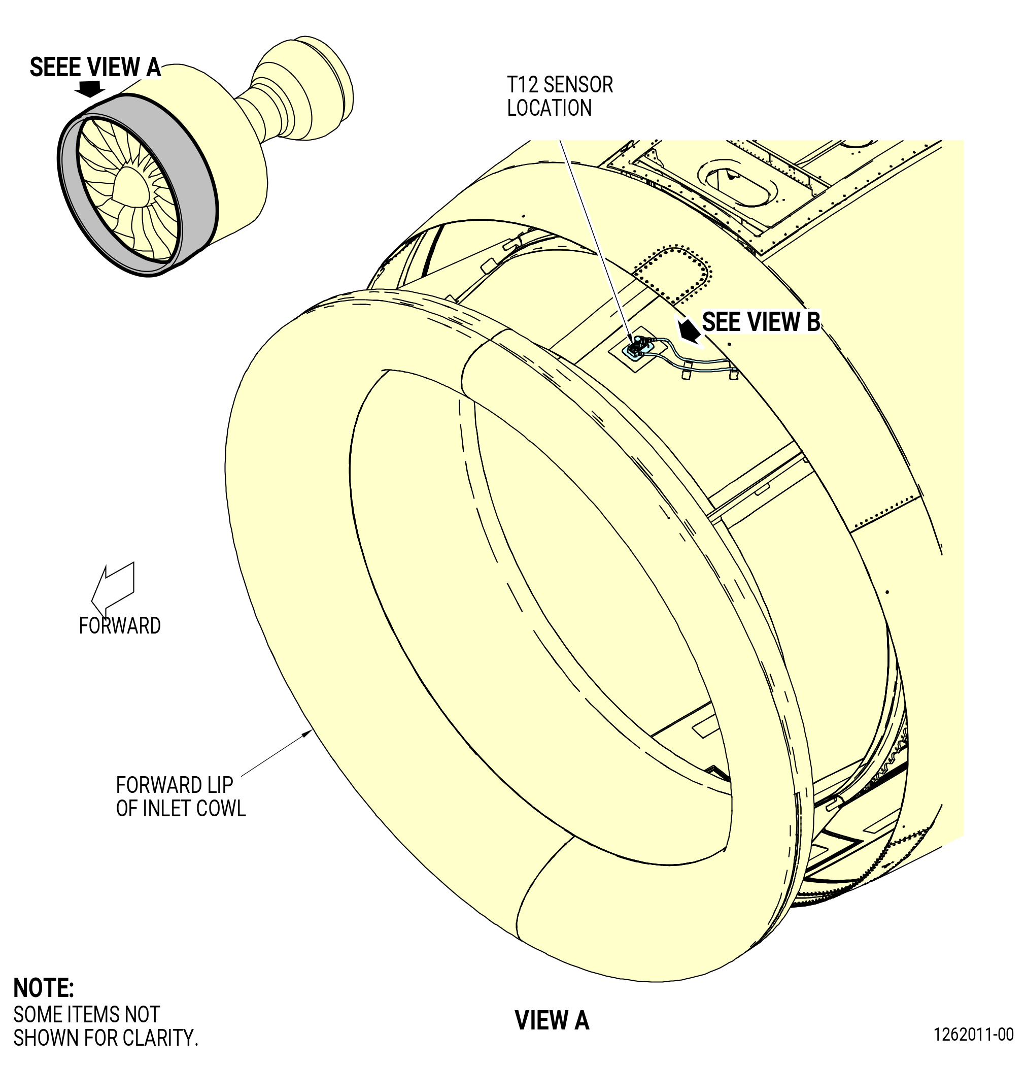
| A. | This procedure gives instructions to remove the T12 sensor. The T12 sensor measures total temperature at the fan inlet and is located forward of the engine, at the 12:00 o'clock position on the inlet cowl. Refer to Figure 301. |
| 2 . | Tools, Equipment, and Materials. |
| NOTE: |
|
| A. | Tools and Equipment. |
| (1) | Special Tools. None. |
| (2) | Standard Tools and Equipment. |
|
| (3) | Locally Manufactured Tools. None. |
| B. | Consumable Materials. None. |
| C. | Referenced Procedures. None. |
| D. | Expendable Parts. None. |
| 3 . | Procedure. |
| Subtask 71-00-00-020-018 |
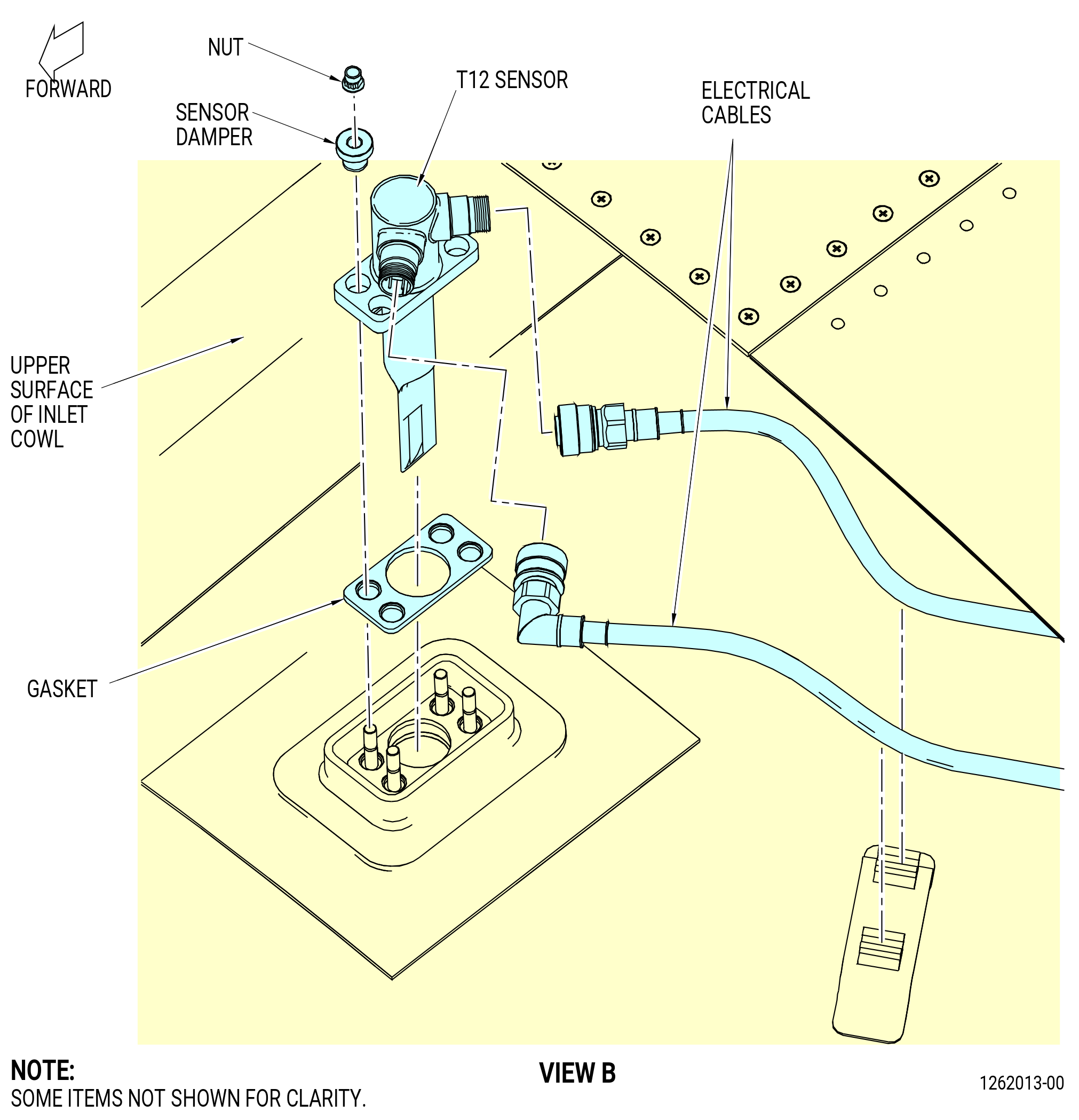
| A. | Remove the T12 sensor as follows. Refer to Figure 301. |
| (1) | Get access to the T12 sensor through an access panel at approximately 12:00 o'clock position on the inlet cowl. |
| CAUTION: |
|
| CAUTION: |
|
| (2) | Remove the two electrical cables from the T12 sensor. |
| (3) | Loosen and remove the four nuts that attach the T12 sensor to the inlet cowl. |
| (4) | Remove the four sensor dampers from the studs on the inlet cowl. |
| (5) | Remove the T12 sensor and remove the gasket from the inlet cowl. |