| GENX-1B ENGINE MANUAL | Dated: 09/13/2023 | |
| EM 72-00-24 , INSTALLATION 001 | ||
| NO. 2 BEARING ASSEMBLY - INSTALLATION 001 | ||
| GENX-1B ENGINE MANUAL | Dated: 09/13/2023 | |
| EM 72-00-24 , INSTALLATION 001 | ||
| NO. 2 BEARING ASSEMBLY - INSTALLATION 001 | ||
| * * * FOR ALL |
| TASK 72-00-24-420-802 |
| 1 . | General. |
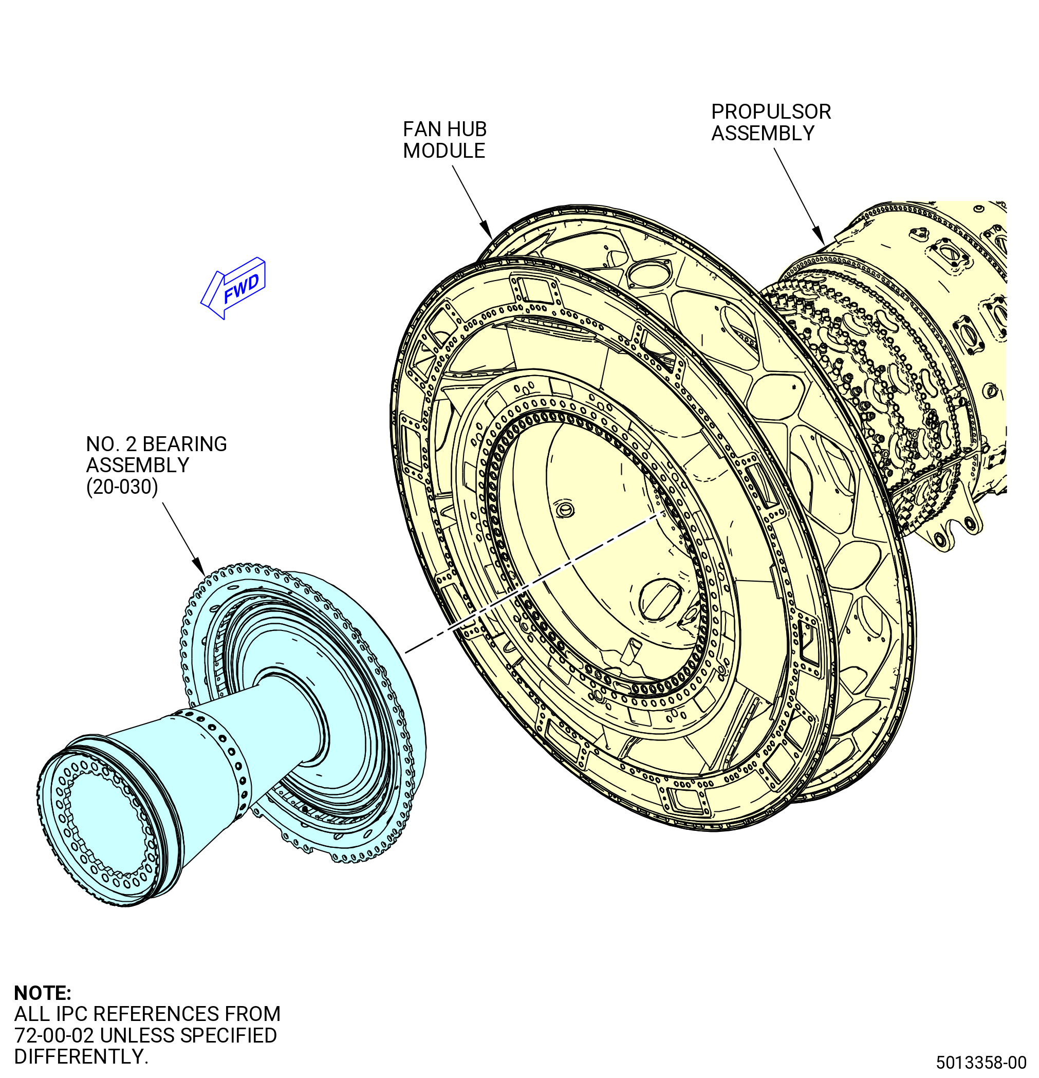
| A. | This procedure gives instructions to install the No. 2 bearing assembly (20-030 , 72-00-02) (SIN 01200). Refer to Figure 401. |
| B. | This procedure starts with the fan hub module, high pressure compressor (HPC) module assembly, and high pressure turbine (HPT) module assembled in the horizontal position and installed on pedestals or installed in the 11C3044 adapter assembly, attached to the customer overhead rail system. |
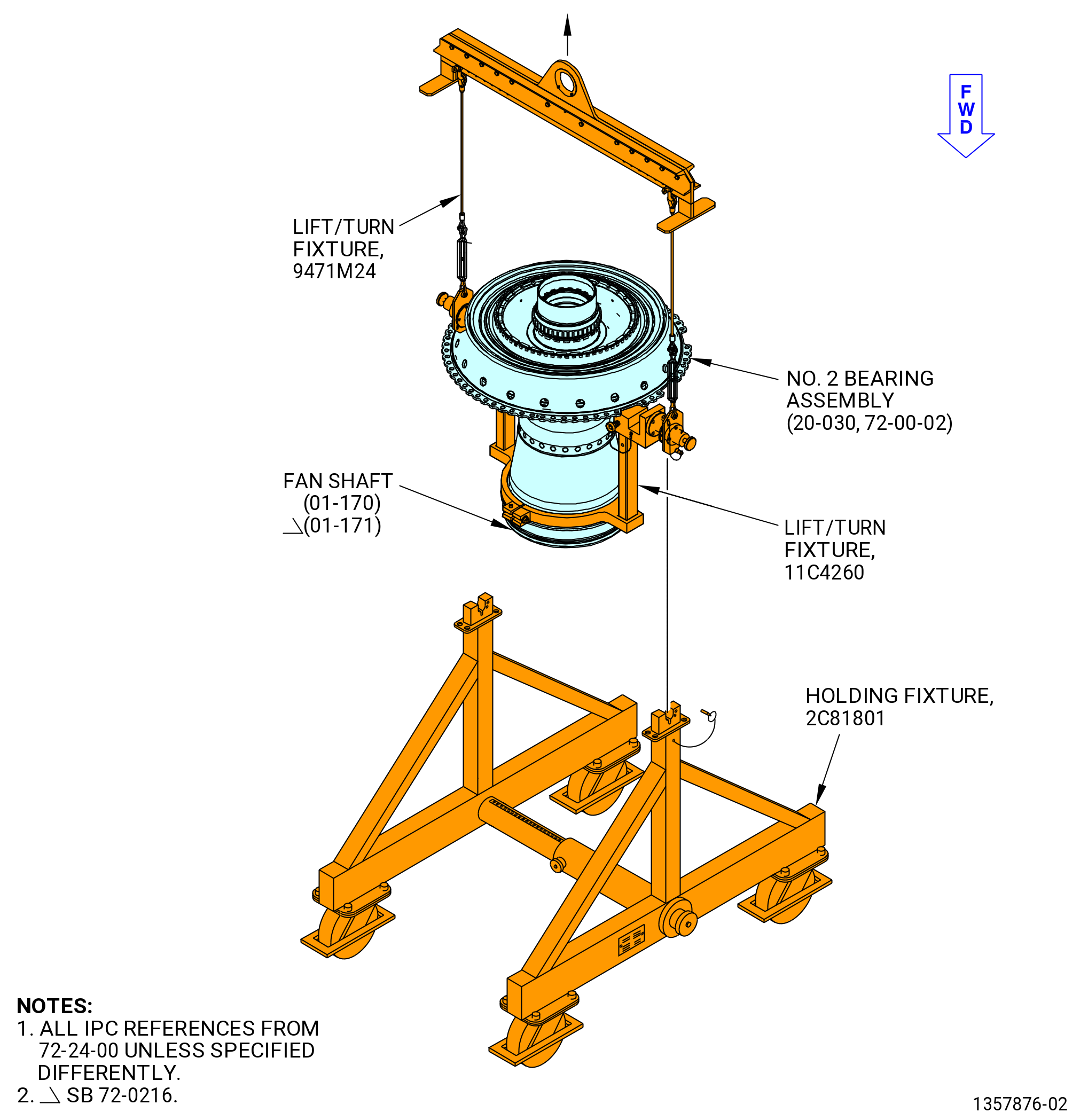
| C. | The No. 2 ball bearing assembly is in the vertical position on the 2C81801 holding fixture with the 11C4260 lift/turn fixture and optionally with the 11C4881 handling fixture. Refer to Figure 403. |
| NOTE: |
|
| D. | Make sure that personnel read this procedure and know the step-by-step instructions and special tool usage before they install the No. 2 bearing assembly. |
| E. | Make sure that there is no unwanted material in the engine or on the engine parts. |
| F. | Make sure that all parts are serviceable before they are installed. |
| G. | Make sure that the No. 2 bearing assembly, the HPC module assembly, and the HPT module, and assembled engine have the correct support at all times to prevent injury to personnel or damage to engine parts. |
| H. | Be careful with the components of the No. 2 bearing assembly. Refer to TASK 70-14-00-620-003 (HANDLING OF BEARINGS) and TASK 70-60-01-620-002 (PRESERVATION OF ANTIFRICTION BEARINGS) . |
| CAUTION: |
|
| I. | Make sure the No. 2 bearing ball (012A0) components do not come in contact with bare hands. When personnel touch the roller bearing components, latex C10-140 gloves must be worn. |
| WARNING: |
|
| J. | Make sure that all mating surfaces are clean before you assemble the parts. If necessary, clean the parts with C04-002 Stoddard solvent, C04-035 isopropyl alcohol, or a 50-50 blend of C04-014 denatured alcohol and C04-035 isopropyl alcohol. |
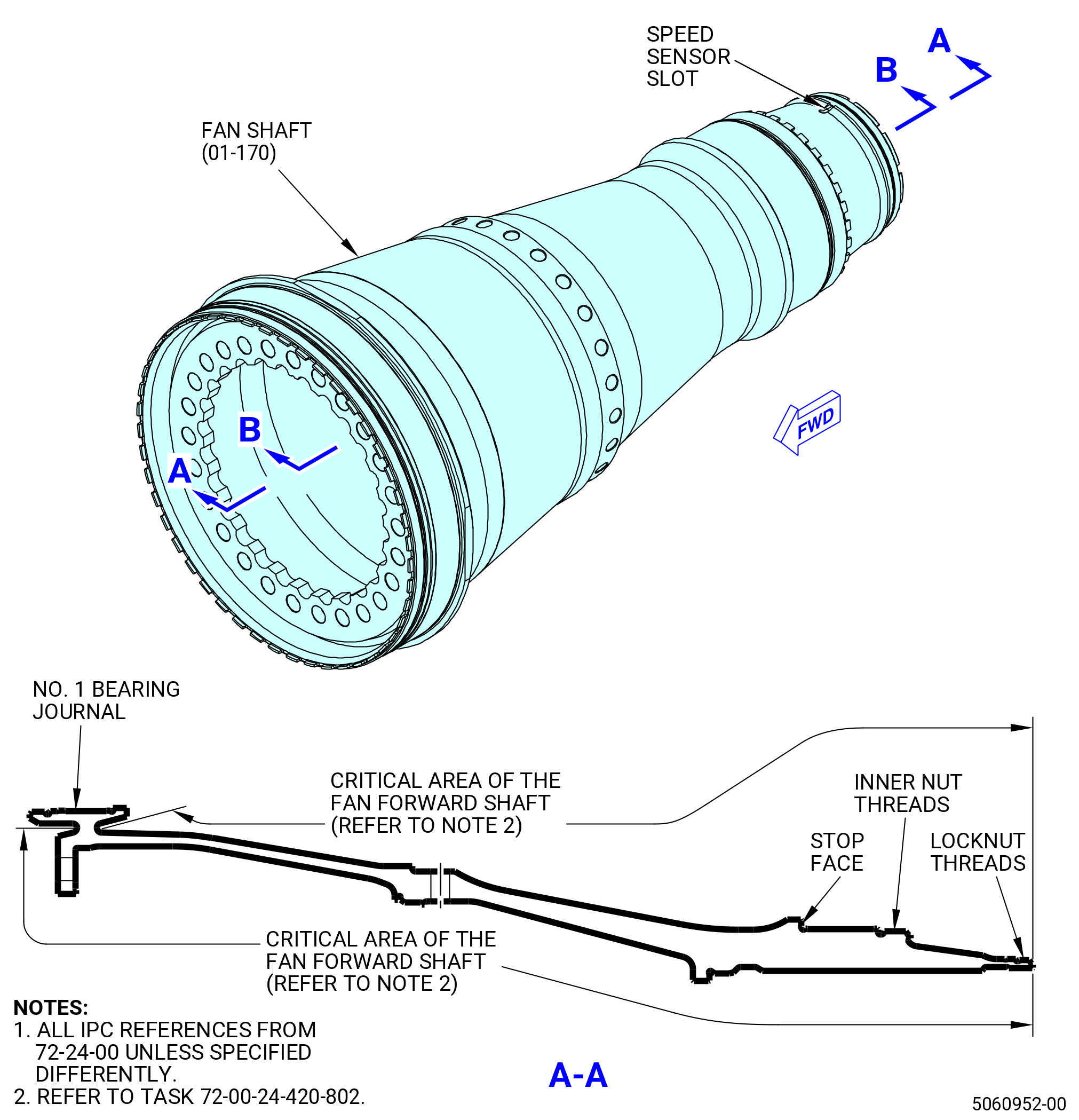
| K. | This assembly contains critical areas of the shaft, that require caution and visual inspection during the assembly process, that are identified throughout this procedure. Refer to Figure 402. |
| 2 . | Tools, Equipment, and Materials. |
| NOTE: |
|
| A. | Tools and Equipment. |
| (1) | Special Tools. |
| (2) | Standard Tools and Equipment. |
|
| (3) | Locally Manufactured Tools. None. |
| B. | Consumable Materials. |
|
| C. | Referenced Procedures. |
|
| D. | Expendable Parts. |
|
| 3 . | Procedure. |
| Subtask 72-00-24-420-010 |
| A. | Prepare the fan hub module to receive the No. 2 bearing assembly (20-030 , 72-00-02) (SIN 01200). Refer to Figure 401 and do as follows: |
| (1) | Install the shear bolts (20-450 , 72-00-02) (SIN 01220) at 64 locations from the aft side of the fan hub frame (FHF) inner flange. The boltheads point aft and the flat side of the shear bolts points outboard. Refer to Figure 404. |
| (2) | Install the push-on nuts (20-350 , 72-00-02) (SIN 01282) at 64 locations from the forward side of the FHF inner flange. Make sure that the push-on nuts are past the shear bolts threads and give sufficient locking to the shear bolts. |
| Subtask 72-00-24-420-011 |
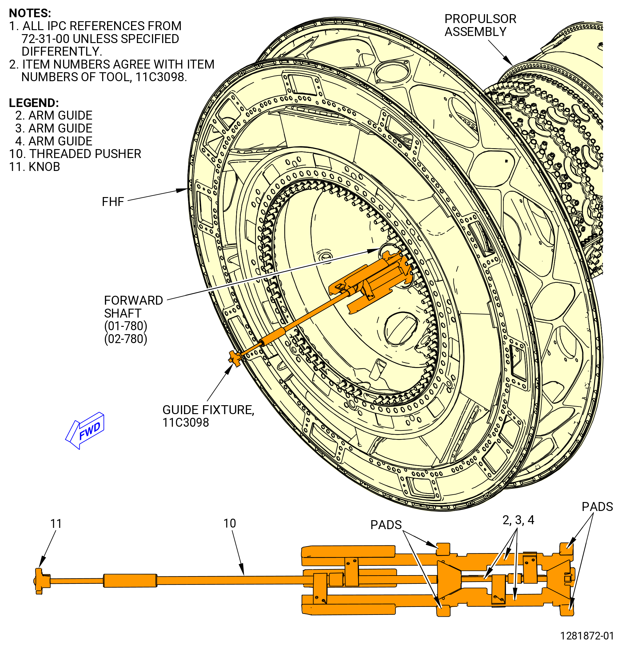
| B. | Install the 11C3098 guide fixture in the forward shaft (01-780 , 72-31-00) (SIN 050B5) or (02-780 , 72-31-00) (SIN 050B5). Refer to Figure 405 and do as follows: |
| (1) | Turn the knob (item 11) and make sure that the arms guide (2, 3, 4) are fully retracted. |
| (2) | Use your hands to install the 11C3098 guide fixture smoothly on the engine centerline in the FHF and in the forward shaft. |
| (3) | Hold the threaded pusher (item 10) and turn the knob (item 11) counterclockwise (forward looking aft) until the pads of the arms guide extend and compress firmly against the inside diameter of the forward shaft. |
| Subtask 72-00-24-420-012 |
| CAUTION: |
|
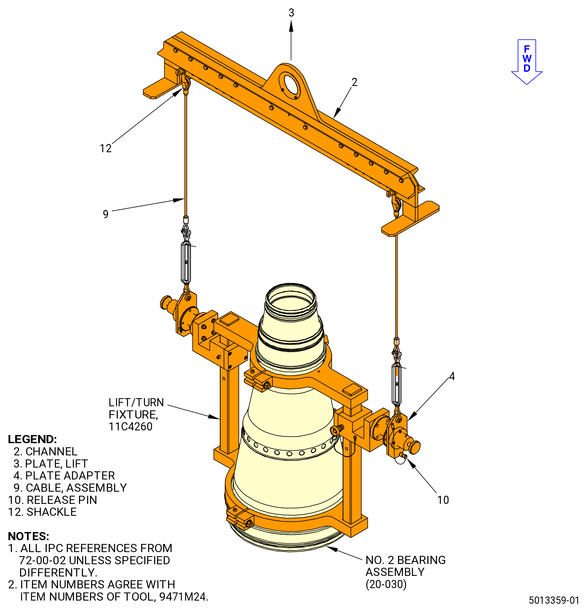
| C. | Attach the 9471M24 lift/turn fixture to the 11C4260 lift/turn fixture. Refer to Figure 406 and do as follows: |
| WARNING: |
|
| (1) | Attach the load scale to the overhead hoist. |
| (2) | Attach the lift plate (item 3) of the 9471M24 lift/turn fixture to the load scale. |
| (3) | Put the shackle (item 12) on the cable assembly (item 9) in the same numbered hole in the lift plate (item 3). Make sure that the cable assembly is straight up from the 11C4260 lift/turn fixture. |
| (4) | Pull on the release pin (item 10) of the 9471M24 lift/turn fixture to permit the lock plate adapter (item 4) to be installed on the trunnion of the 11C4260 lift/turn fixture. |
| (5) | Install the release pin (item 10) of the 9471M24 lift/turn fixture in the lock plate adapter (item 4). |
| Subtask 72-00-24-420-013 |
| CAUTION: |
|
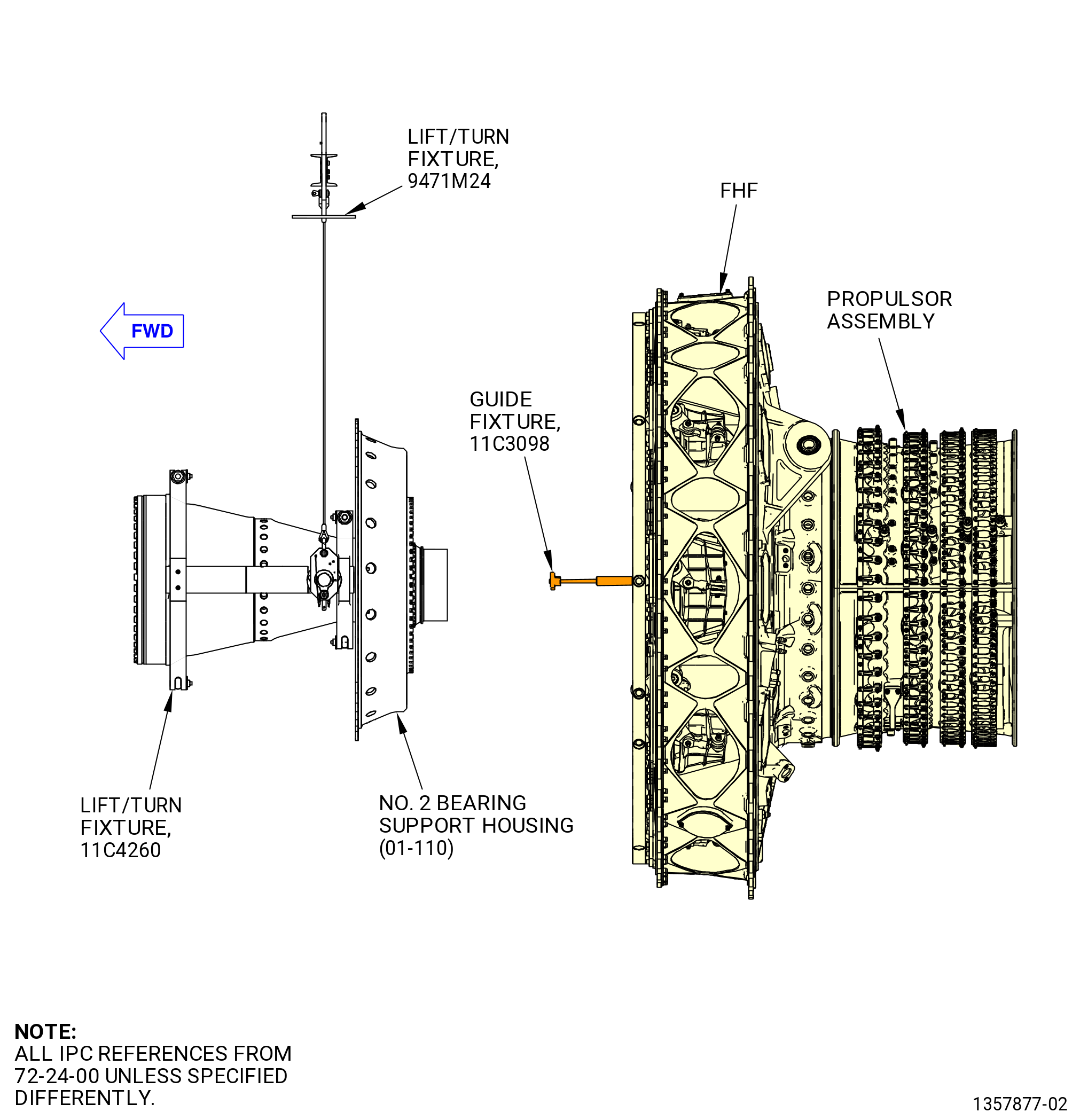
| D. | Lift the No. 2 bearing assembly (20-030 , 72-00-02) (SIN 01200) with the 9471M24 lift/turn fixture. Refer to Figure 407 and do as follows: |
| WARNING: |
|
| CAUTION: |
|
| (1) | Use the hoist to slowly move the No. 2 bearing assembly near the FHF as follows: |
| (a) | Make sure that the centerline of the No. 2 bearing assembly is aligned with the centerline of the FHF. Use visual indicators to make sure that the modules are aligned. |
| 1 | Use the 11C3098 guide fixture installed in the forward shaft (01-780 , 72-31-00) (SIN 050B5) or (02-780 , 72-31-00) (SIN 050B5) as a visual indicator to align the No. 2 bearing assembly with the FHF. |
| 2 | Use the alignment of the boltholes on the perimeter of the No. 2 bearing support housing and the shear bolts in the FHF as a visual indicator. |
| (b) | Stop the No. 2 bearing support housing when 3-4 feet (0.9-1.2 m) of space remains between the two modules. |
| NOTE: |
|
| Subtask 72-00-24-420-014 |
| CAUTION: |
|
| E. | Install the No. 2 Bearing Assembly (20-030 , 72-00-02) (SIN 01200) on the FHF. Refer to Figure 408 and do as follows: |
| Subtask 72-00-24-160-001 |
| WARNING: |
|
| (1) | Before the installation of the No. 2 bearing assembly on the fan hub frame, do a last chance wipe of the aft side of the fan extension shaft, where the oil supply comes from, using new C10-182 wipers with clean C02-019 engine oil. |
| Subtask 72-00-24-420-025 |
| (2) | Prepare the self-locking nuts (20-340 , 72-00-02) (SIN 01240) to attach the No. 2 bearing assembly to the FHF as follows: |
| WARNING: |
|
| (a) | Apply C02-058 lubricant to the threads and seating surfaces of the 64 self-locking nuts (20-340 , 72-00-02) (SIN 01240). |
| WARNING: |
|
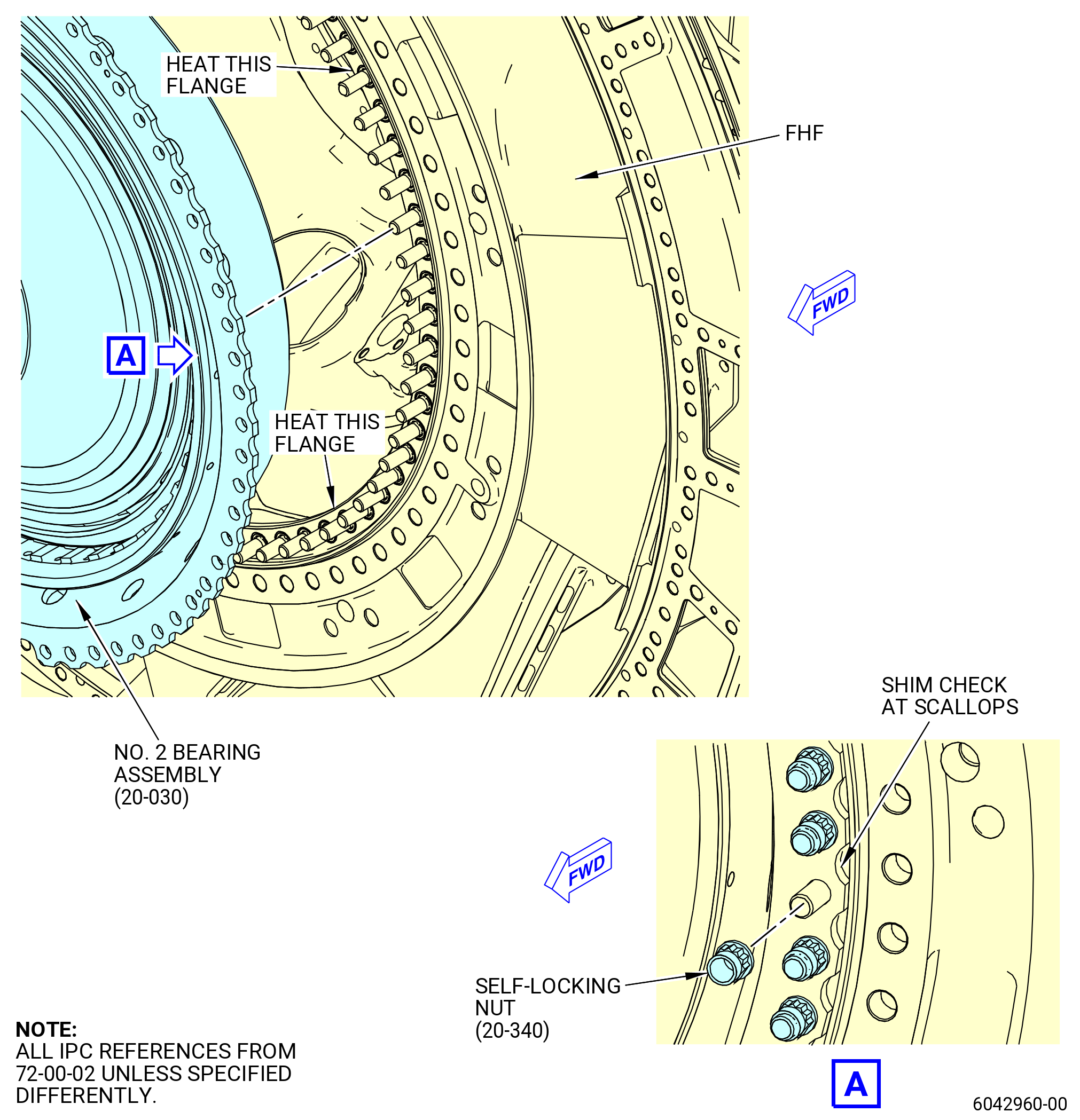
| (3) | If necessary, use a heat gun to increase the temperature of the mating surface of the forward flange of the FHF to 220ºF (104ºC). |
| (4) | Use a temperature probe and make sure that the temperature of the flange is at 250ºF (121ºC). |
| WARNING: |
|
| (5) | Use the hoist and hydra-set and slowly move the No. 2 bearing assembly into contact with the FHF. Make sure that the No. 2 bearing support housing engages with the shear bolts (20-450 , 72-00-02) (SIN 01220) and the 11C3098 guide fixture. |
| (6) | Attach the No. 2 bearing housing to the FHF as follows: |
| (a) | Install the self-locking nuts (20-340 , 72-00-02) (SIN 01240) in groups of three at eight equally spaced locations on the FHF flange. |
| (b) | Torque the self locking nuts to 300-320 lb in. (33.9-36.1 N.m). This will seat the No. 2 bearing support housing on the FHF rabbet. |
| (7) | Let the FHF forward flange return to room temperature. Use a temperature probe and make sure that the flange is between 60-80ºF (16 to 26ºC). |
| (8) | Install the remaining 40 self-locking nuts (20-340 , 72-00-02) (SIN 01240). |
| (9) | Torque all 64 self locking nuts (20-340 , 72-00-02) (SIN 01240) to 851-999 lb in. (96.2-112.9 N.m) in a criss-cross pattern. |
| (10) | Circle torque the nuts again to 851-999 lb in. (96.2-112.9 N.m). |
| Subtask 72-00-24-220-004 |
| (11) | Use a 0.001 inch (0.025 mm) shim and do a clearance check of the seating of the No. 2 bearing support housing aft flange to the FHF forward flange. Do the clearance check at the scalloped-shaped edges of the No. 2 bearing support housing. Refer to Figure 408. |
| Subtask 72-00-24-420-015 |
| CAUTION: |
|
| F. | Remove the 9471M24 lift/turn fixture to the 11C4260 lift/turn fixture from the No. 2 bearing support housing. These tools will be used again to install the No. 1 bearing housing in a later step. |
| Subtask 72-00-24-420-024 |
| CAUTION: |
|
| G. | Remove the 11C3098 guide fixture as follows. Refer to Figure 405. |
| (1) | Use your hands and reach inside the No. 2 bearing support housing to reach the 11C3098 guide fixture. |
| (2) | Hold the threaded pusher (item 10) to turn the knob (item 11) of the 11C3098 guide fixture clockwise (forward looking aft) to retract the arm guides (items 2) thru (item 4) and slowly slide the tool forward and out of the forward shaft and then out of the forward shaft. Put the 11C3098 guide fixture tool back into storage. |
| Subtask 72-00-24-220-006 |
| (3) | Do a general visual inspection of the exposed surfaces of the forward fan shaft for nicks, dents, and scratches after the removal of tooling. Refer to TASK 72-00-24-200-801 (72-00-24, INSPECTION 001) and Figure 402. |
| Subtask 72-00-24-420-016 |
| H. | Continue to assemble the engine. To install the No. 1 bearing assembly, refer to TASK 72-00-23-420-801 (72-00-23, Installation). |