| GENX-1B ENGINE MANUAL | Dated: 12/21/2020 | |
| EM 72-24-00 , DISASSEMBLY 001 | ||
| NO. 2 BALL BEARING ASSEMBLY - DISASSEMBLY 001 | ||
| GENX-1B ENGINE MANUAL | Dated: 12/21/2020 | |
| EM 72-24-00 , DISASSEMBLY 001 | ||
| NO. 2 BALL BEARING ASSEMBLY - DISASSEMBLY 001 | ||
| * * * FOR ALL |
| TASK 72-24-00-040-801 |
| 1 . | General. |
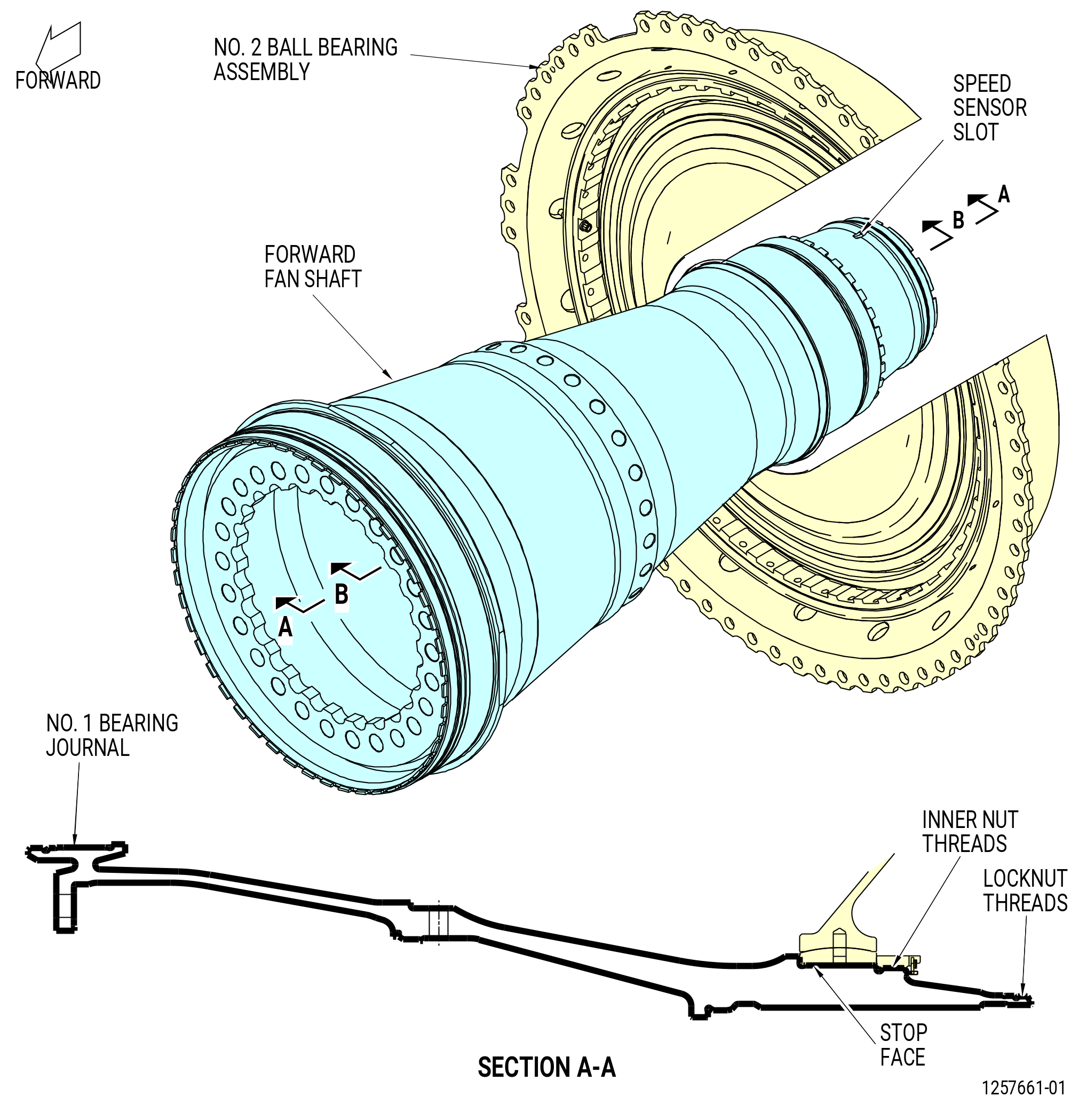
| A. | This procedure gives instructions to disassemble the No. 2 ball bearing assembly (20-030 , 72-00-02) (SIN 01200). Refer to Figure 501. |
| B. | This procedure begins with the No. 2 ball bearing assembly on the 2C81801 holding fixture with the 11C4260 lift/turn fixture. |
| C. | Bearings. |
| (1) | Be careful with the components of the No. 2 ball bearing assembly. Refer to TASK 70-14-00-620-003 (HANDLING OF BEARINGS) and TASK 70-60-01-620-002 (PRESERVATION OF ANTIFRICTION BEARINGS) . |
| (2) | Keep the ball bearing components (balls, cages, inner races, and outer races) as a set by serial number. The ball bearing is a matched assembly. Do not mix serviceable ball bearing components with the components of different serial numbers. |
| (3) | Do not touch the ball bearing components with bare hands. Wear clean, Latex C10-140 gloves when ball bearing components are touched. |
| (4) | Do not touch the cage or balls of the No. 2 ball bearing assembly with assembly/installation tools. |
| 2 . | Tools, Equipment, and Materials. |
| NOTE: |
|
| A. | Tools and Equipment. |
| (1) | Special Tools. |
| (2) | Standard Tools and Equipment. |
|
| (3) | Locally Manufactured Tools. None. |
| B. | Consumable Materials. |
|
| C. | Referenced Procedures. |
|
| D. | Expendable Parts. None. |
| 3 . | Procedure. |
| Subtask 72-24-00-040-001 |
| A. | Remove the No. 2 ball bearing assembly (20-030 , 72-00-02) (SIN 01200) from the 2C81801 holding fixture as follows: |
| Subtask 72-24-00-040-007 |
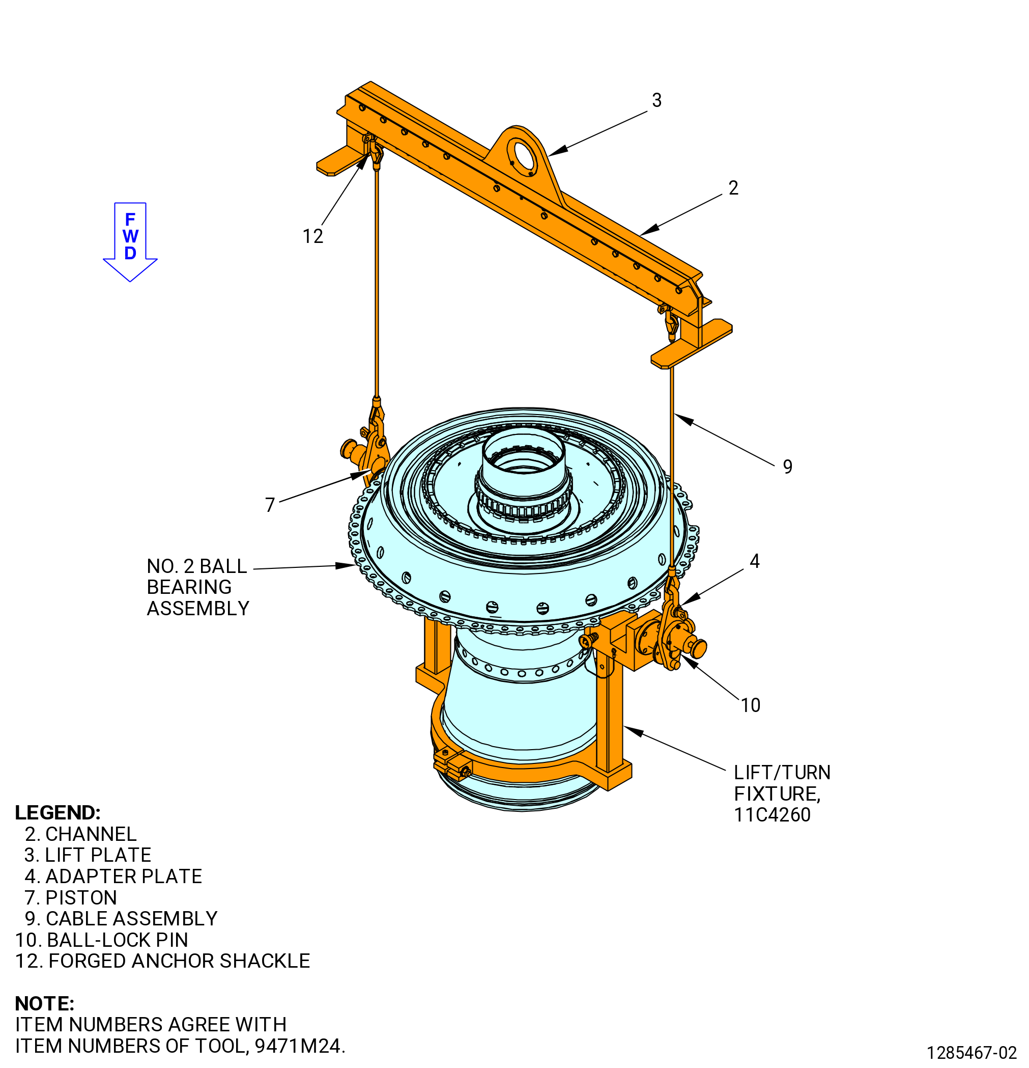
| (1) | Attach the 9471M24 lift/turn fixture to the 11C4260 lift/turn fixture. Refer to Figure 502 and do as follows: |
| WARNING: |
|
| (a) | Attach the cable assembly (item 9) to the lift plate (item 3) with the forged anchor shackle (item 12) of the 9471M24 lift/turn fixture. Make sure that they have the same number of holes on the lift plate (item 3) outside of the cable assembly (item 9) to keep the 9471M24 lift/turn fixture balanced. |
| (b) | Attach the lock plate adapters (item 4) to the cable assembly (item 9). |
| (c) | Deleted. |
| (d) | Deleted. |
| WARNING: |
|
| (2) | Deleted. |
| Subtask 72-24-00-040-071 |
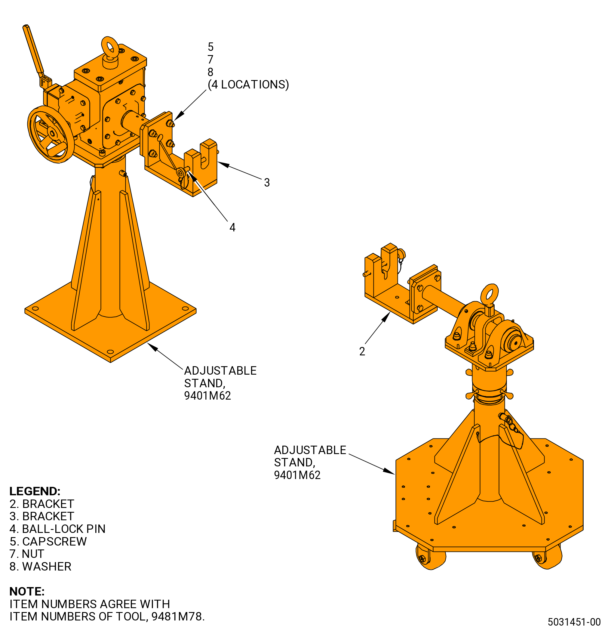
| (3) | Install the 9481M78 bracket adapter on the 9401M62 adjustable stand. Refer to Figure 504 and do as follows: |
| (a) | Put the bracket (item 3) on the stationary support of the 9401M62 adjustable stand. |
| (b) | Attach the bracket (item 3) with the capscrews (item 5), the washers (item 8), and the nuts (item 7) at four locations. Tighten the nuts (item 7). |
| (c) | Put the bracket (item 2) on the portable support of the 9401M62 adjustable stand. |
| (d) | Attach the bracket (item 2) with the capscrews (item 5), the washers (item 8), and the nuts (item 7) at four locations. Tighten the nuts (item 7). |
| (e) | Remove the ball-lock pins (item 4) from the brackets (item 2 and 3). |
| Subtask 72-24-00-040-072 |
| (4) | Install the No. 2 ball bearing assembly on the 9401M62 adjustable stand. Refer to Figure 505 and do as follows: |
| (a) | Make sure that the ball-lock pins (item 21) are installed at two locations on the fixed and adjustable supports. |
| (b) | Move the lever (item 10) to the inward position to let the fixed adapter (item 12) rotate. |
| WARNING: |
|
| (c) | Lift the No. 2 ball bearing assembly in the 11C4260 lift/turn fixture. |
| (d) | Lower and align the trunnions (item 8) of the 11C4260 lift/turn fixture with the slots on the 9481M78 bracket adapter at two locations. Refer to Figure 505. |
| 1 | If necessary, loosen the locknut (item 16) of the 9401M62 adjustable stand and turn the support adjustment nut (item 15) to adjust the height of the shaft (item 6) on the portable support. Make sure that the forward fan shaft is level. |
| 2 | Tighten the locknut (item 16). |
| (e) | Install the ball-lock pin (item 4) of the 9481M78 bracket adapter in the bracket (item 2) to secure the trunnion (item 8) of the 11C4260 lift/turn fixture. Refer to Figure 504. |
| (f) | Remove the 9471M24 lift/turn fixture from the trunnions on the 11C4260 lift/turn fixture. Refer to Figure 505. |
| CAUTION: |
|
| (g) | Put the floor locks (item 25) of the 9401M62 adjustable stand down until they touch the floor. |
| (h) | Use the hand wheel (item 13) to turn the No. 2 ball bearing assembly to put the forward end up. |
| CAUTION: |
|
| (i) | Move the lever (item 10) to the outward position to prevent rotation of the No. 2 ball bearing assembly. |
| (5) | Remove the 9471M24 lift/turn fixture from the 11C4260 lift/turn fixture. |
| Subtask 72-24-00-040-073 |
| CAUTION: |
|
| B. | Remove the No. 1 cylindrical roller bearing (No. 1 bearing) (01-080 , 72-23-00) (SIN 011A0) inner race. Refer to Figure 506 and do as follows: |
| (1) | Rotate the No. 2 ball bearing assembly in the 9401M62 adjustable stand to put the forward end in the up position. Refer to Figure 505 and do as follows: |
| (a) | Move the lever (item 10) to the inward position. |
| CAUTION: |
|
| (b) | Use the hand wheel (item 13) to turn the forward fan shaft to put the forward end in the up position. |
| (c) | Move the lever (item 10) to the outward position to prevent rotation of the forward fan shaft. |
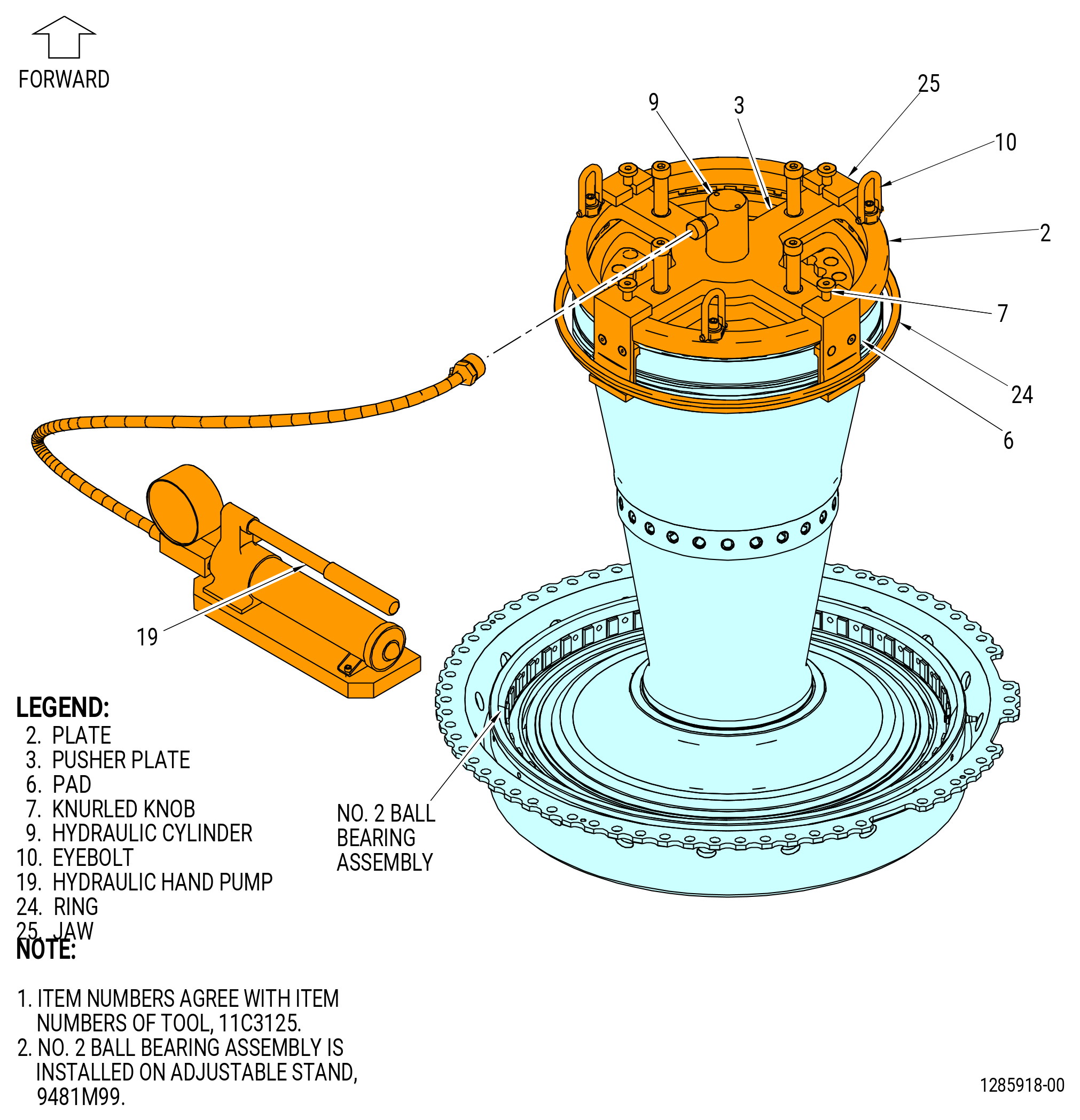
| (2) | Attach a three-piece sling to the eyebolt (item 10) of the 11C3125 puller. Refer to Figure 506. |
| WARNING: |
|
| (3) | Attach an overhead hoist to the three-piece sling and lower the 11C3125 puller onto the forward end of the forward fan shaft. |
| (4) | Turn the knurled knobs (item 7) to remove the pads (item 6). |
| (5) | Align the plate (item 2) with the forward flange of the forward fan shaft. |
| (6) | Lower the 11C3125 puller onto the shaft until the pusher plate (item 3) is against the forward flange. |
| (7) | Align and install the four pads (item 6) with the four flat areas on the shaft outside diameter (OD). |
| (8) | Make sure that the pads (item 6) are correctly aligned in the flat areas of the shaft OD. |
| (9) | Turn the knurled knobs (item 7) to tighten the pads (item 6) against the aft surface of the inner race. |
| (10) | Install the ring (item 24) to hold the jaws (item 25). |
| WARNING: |
|
| (11) | Operate the hydraulic hand pump (item 19) to disengage the inner race from the shaft. |
| (12) | Remove the 11C3125 puller. |
| (13) | Remove the No. 1 bearing inner race and wrap in a piece of C10-009 greaseproof. |
| Subtask 72-24-00-620-005 |
| WARNING: |
|
| C. | If necessary, do the preservation procedure for the No. 1 bearing (01-080 , 72-23-00) (SIN 011A0) inner race with C02-050 preservation oil. Refer to TASK 70-60-01-620-002 (PRESERVATION OF ANTIFRICTION BEARINGS) for preservation steps and time limits. |
| Subtask 72-24-00-040-074 |
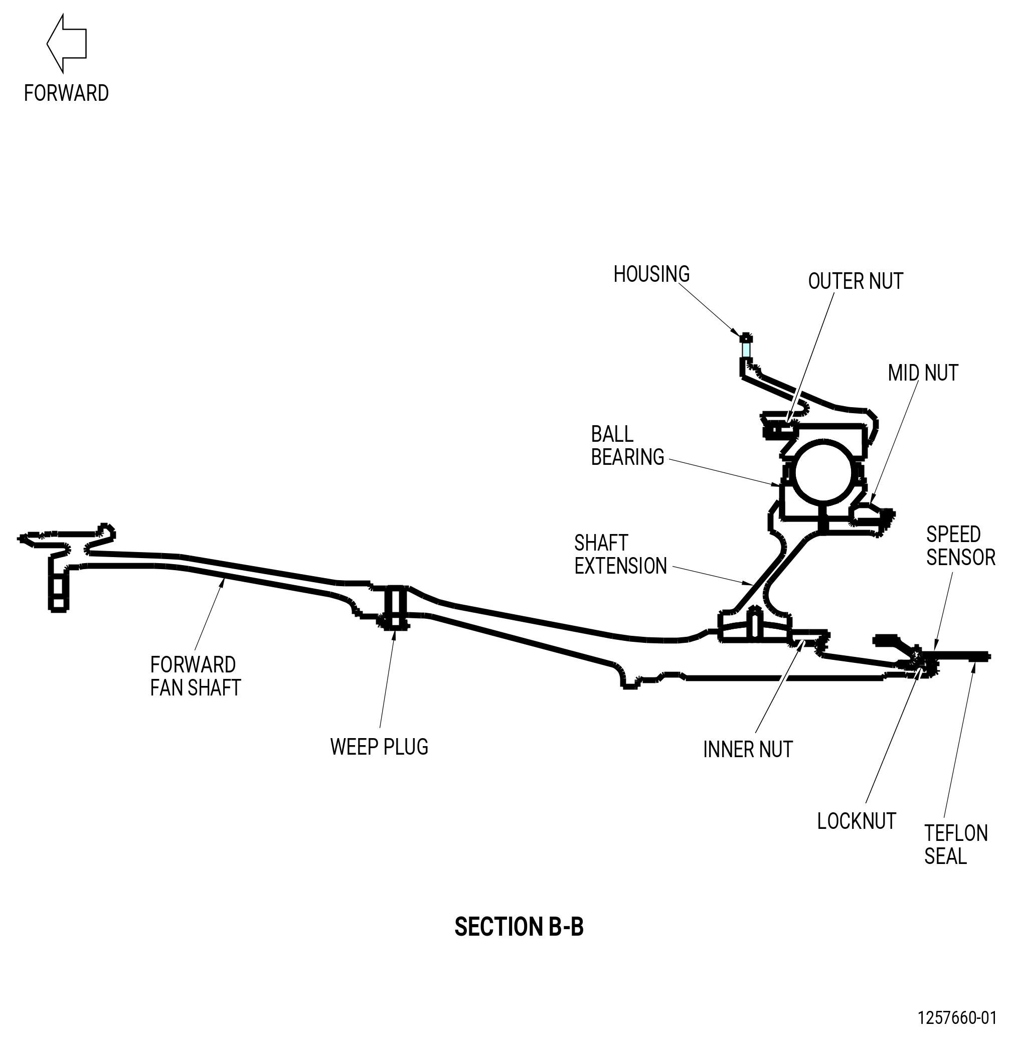
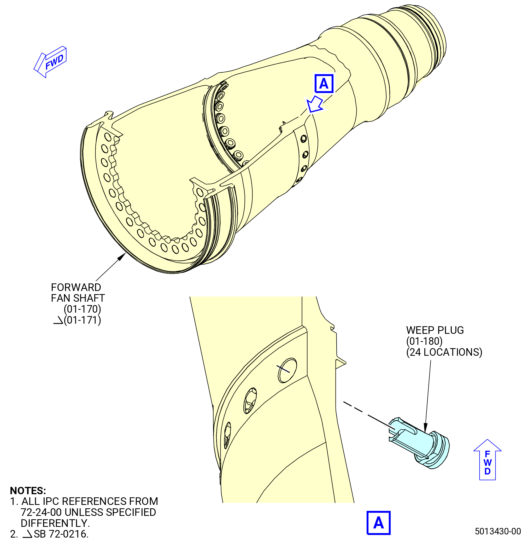
| D. | Remove the fan shaft weep plugs (weep plugs) (01-180) (SIN 81090) from the holes on the forward fan shaft (01-170) (SIN 81002) or (01-171) (SIN 81002). Refer to Figure 507 and do as follows: |
| (1) | Push the weep plug from the OD of the forward fan shaft to the inside diameter (ID) of the forward fan shaft until the retention feature is through the hole. |
| (2) | Remove the weep plug from the forward fan shaft. |
| Subtask 72-24-00-040-049 |
| E. | Remove the round nut (locknut) as follows: |
| (1) | Rotate the No. 2 ball bearing assembly in the 9401M62 adjustable stand to put the aft end in the up position. Refer to Figure 505 and do as follows: |
| (a) | Move the lever (item 10) to the inward position. |
| (b) | Use the hand wheel (item 13) to rotate the forward fan shaft to put the aft end in the up position. |
| CAUTION: |
|
| (c) | Move the lever (item 10) to the outward position to prevent rotation of the No. 2 ball bearing assembly. |
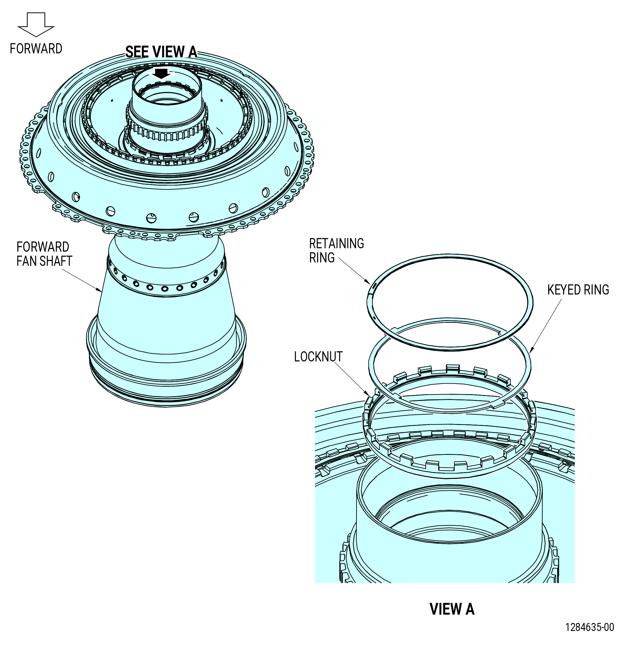
| (2) | Remove the retaining ring and the keyed ring from the locknut. Refer to Figure 508. |
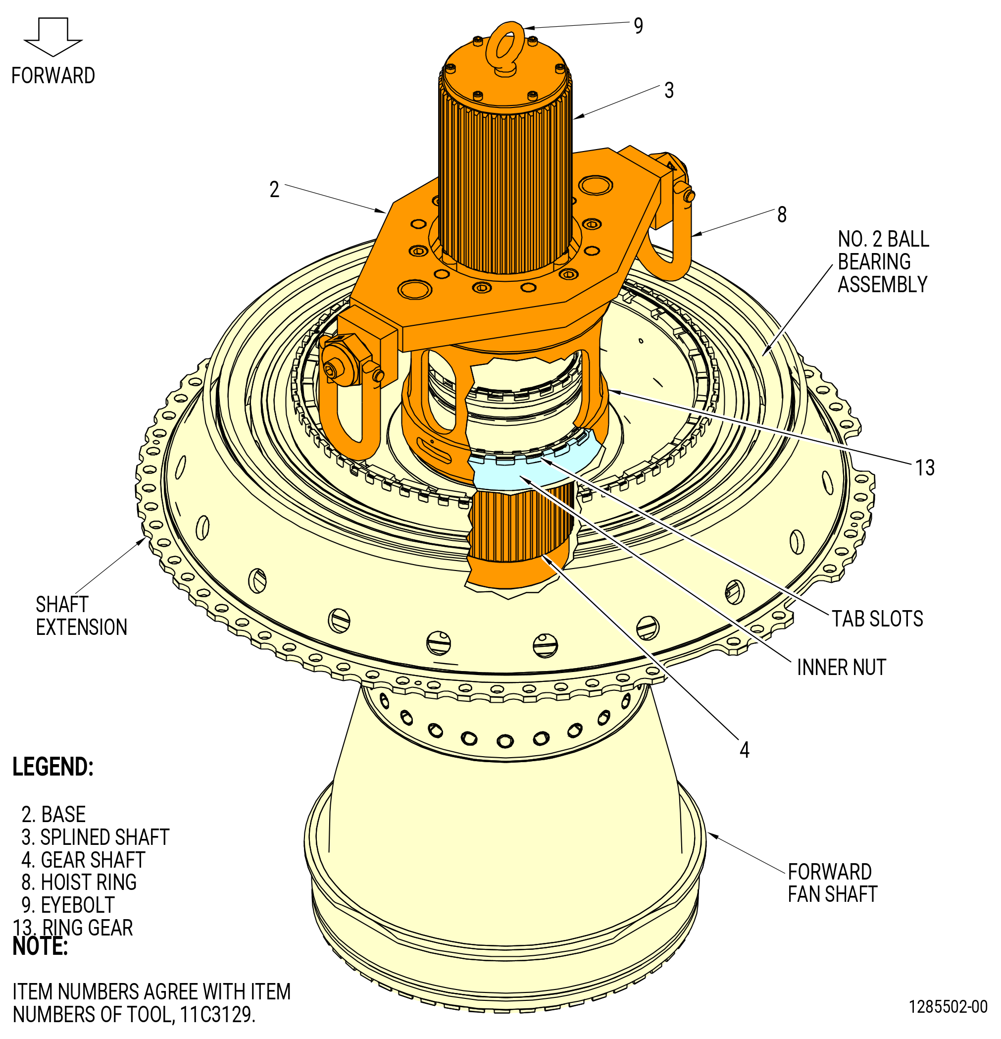
| (3) | Install the 11C3129 adapter as follows. Refer to Figure 509. |
| (a) | Install the base (item 2) and the ring gear (item 7) as follows: |
| 1 | Attach a three-piece sling to the two hoist rings (item 8) of the base (item 2) and to an overhead hoist. |
| NOTE: |
|
| 2 | Lift the base (item 2) with the ring gear (item 7) attached and align it with the forward fan shaft. |
| WARNING: |
|
| (b) | Attach an overhead hoist to the eyebolt (item 9) and lift the splined shaft (item 3) and the gear shaft (item 4) of the 11C3129 adapter over the No. 2 ball bearing assembly. |
| (c) | Lower the spline shaft (item 3) until the gear shaft (item 4) engages the splines in the shaft and do as follows: |
| 1 | Align the hole in the center of the base (item 2) with the spline shaft (item 3). |
| 2 | Align the tabs of the gear ring (item 7) with the tab slots of the locknut. |
| (d) | Remove the overhead hoist from the eyebolt (item 9). |
| (4) | Align the splines of the hydraulic torque multiplier with the spline shaft and install the torque multiplier. |
| (5) | Align the legs of the torque multiplier with the holes in the base (item 2). |
| (6) | Operate the hydraulic torque multiplier in a clockwise (CW) direction to remove the locknut. |
| (7) | Remove the torque multiplier. |
| (8) | Remove the 11C3129 adapter . |
| Subtask 72-24-00-040-050 |
| F. | Remove the fan speed sensor from the forward fan shaft as follows. Refer to Figure 510. |
| (1) | Install the 11C3154 pusher/puller on the rotating air seal as follows: |
| WARNING: |
|
| (a) | Attach an overhead hoist to the hoist ring (item 25) and lift the 11C3154 pusher/puller. |
| (b) | Carefully lower the 11C3154 pusher/puller until the support (item 20) is on the fan speed sensor. |
| (c) | Put the jaws (item 7) around the fan speed sensor at two locations. The lower part of the jaw is engaged with the lip on the fan speed sensor. The upper part of the jaw (item 7) is engaged with the circular groove of the support (item 20). |
| (d) | Put the collar (item 8) around the jaws (item 7) to hold the jaws in position. |
| (2) | Connect a hydraulic hand pump to the coupler (item 27). |
| WARNING: |
|
| (3) | Operate the hydraulic hand pump until the fan speed sensor is removed from the forward fan shaft. The maximum pressure you can apply is 4000 psi (27500 kPa). |
| (4) | Remove the fan speed sensor and the 11C3154 pusher/puller. |
| (5) | Disconnect the hydraulic hand pump from the coupler (item 27). |
| Subtask 72-24-00-040-068 |
| G. | Remove the internal retaining ring as follows. Refer to Figure 511. |
| (1) | Remove the internal retaining ring from the inner nut. |
| (2) | Remove the two clips. |
| Subtask 72-24-00-040-009 |
| H. | Remove the inner nut from the forward fan shaft as follows: |
| (1) | Install the 11C3129 adapter as follows. Refer to Figure 512. |
| (a) | Install the splined shaft (item 3) and the gear shaft (item 4) as follows: |
| WARNING: |
|
| 1 | Attach an overhead hoist to the eyebolt (item 9) to lift the splined shaft (item 3), with the gear shaft (item 4) attached. |
| 2 | Lower the splined shaft (item 3) until the gear shaft (item 4) is engaged with the splines in the shaft. |
| (b) | Install the base (item 2) and the ring gear (item 13) as follows: |
| 1 | Attach the three-piece sling to the two hoist rings (item 8) of the base (item 2) and to an overhead hoist. |
| 2 | Lift the base (item 2), with the ring gear (item 13) attached. |
| 3 | Align the hole in the center of the base (item 2) with the splined shaft (item 3). |
| 4 | Lower the base (item 2) and engage the tabs of the ring gear (item 13) with the tab slots of the locknut. |
| (2) | Install the torque multiplier as follows: |
| (a) | Install the torque multiplier on the base (item 2). |
| (b) | Align the splines of the torque multiplier with the splines of the splined shaft (item 3). |
| (c) | Align the legs of the torque multiplier with the holes in the base (item 2). |
| (3) | Operate the torque multiplier to disengage the inner nut from the shaft. |
| (4) | Remove the torque multiplier with an overhead hoist. |
| (5) | Remove the 11C3129 adapter with an overhead hoist as follows: |
| (a) | Attach the three-piece sling to the two hoist rings (item 8) of the base (item 2) and to an overhead hoist. |
| (b) | Lift the base (item 2), with the ring gear (item 13) attached. |
| (c) | Attach an overhead hoist to the eyebolt (item 9) and lift the splined shaft (item 3), with the gear shaft (item 4) attached. |
| (6) | Remove the inner nut. |
| Subtask 72-24-00-040-053 |
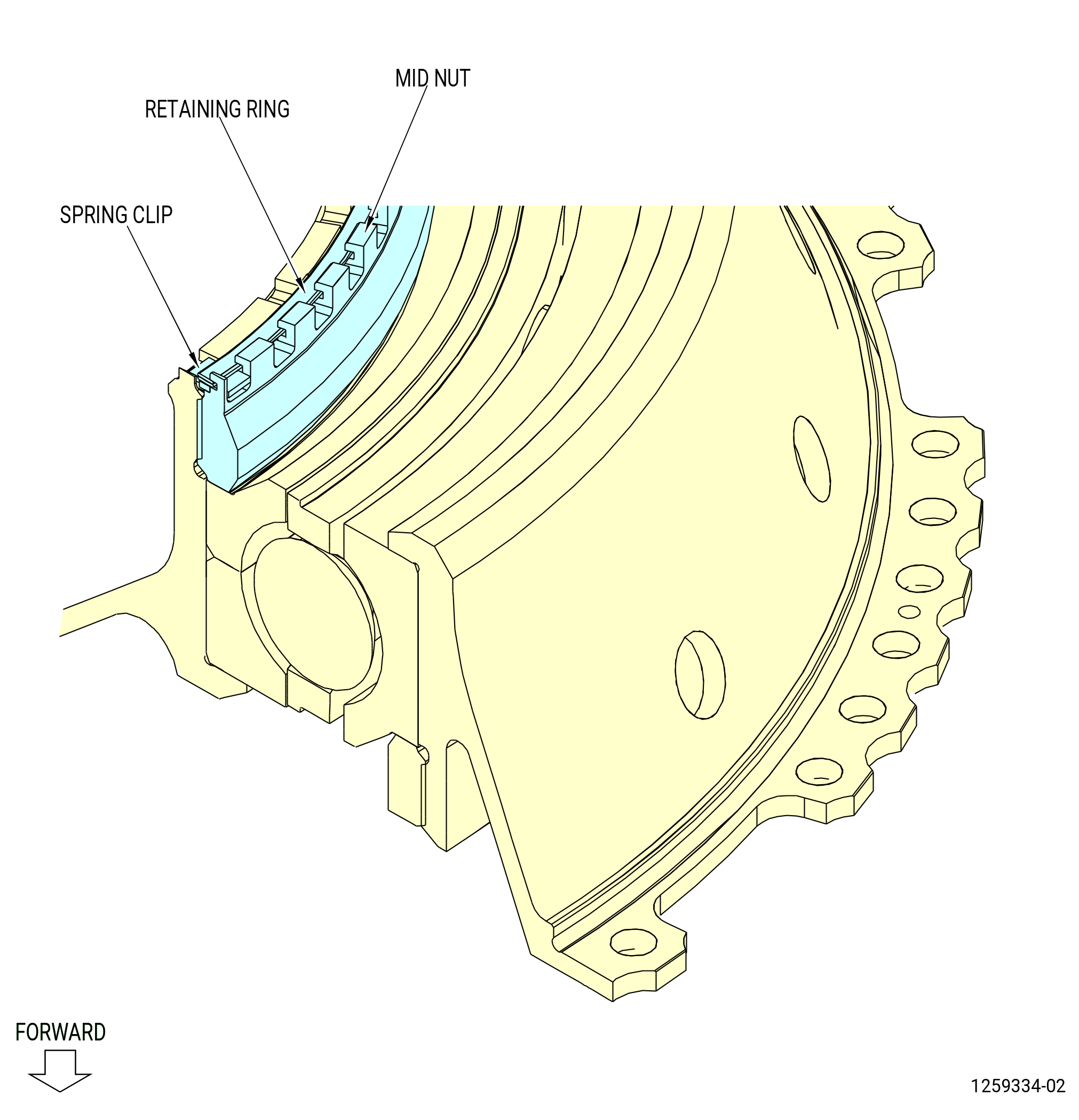
| I. | Remove the mid nut as follows. Refer to Figure 513. |
| (1) | Remove the retaining ring from the groove in the mid nut. |
| (2) | Remove the clips at two locations. |
| WARNING: |
|
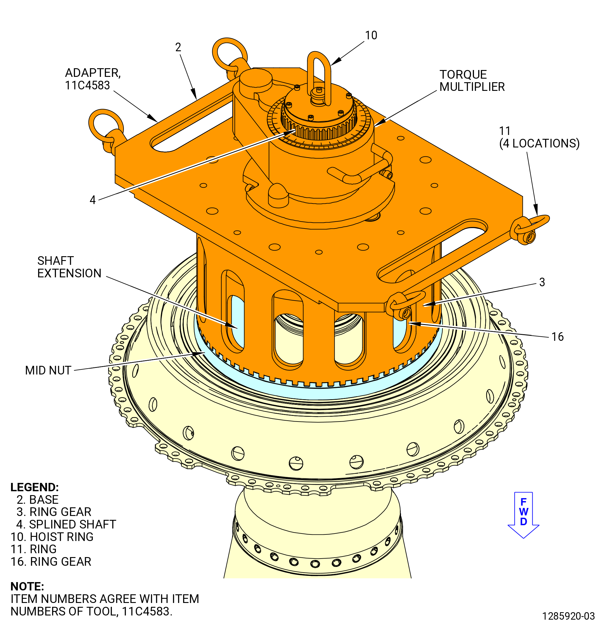
| (3) | Attach an overhead hoist to the ring (item 11) of the 11C4583 adapter on the splined shaft (item 4). |
| (4) | Lift the splined shaft (item 4) with the ring gear (item 16). |
| (5) | Lower the splined shaft (item 4) until the ring gear (item 16) is engaged with the slots on the shaft extension. |
| (6) | Install the base (item 2) and the ring gear (item 3) as follows: |
| (a) | Attach the four-piece sling to the rings (item 11) of the base (item 2) and to an overhead hoist. |
| (b) | Lift the base (item 2) and align the ring gear (item 3) to the ring gear (item 16) while the base is lowered. |
| (c) | Align the tabs of the ring gear (item 3) with the tab slots in the mid nut. |
| (7) | Install the torque multiplier with an overhead hoist as follows: |
| (a) | Align the splines of the torque multiplier with the splined shaft (item 4). |
| (b) | Align the legs of the torque multiplier with the holes in the base. |
| (c) | Install the torque multiplier on the base (item 2). |
| (8) | Actuate the torque multiplier to loosen the mid nut. |
| NOTE: |
|
| (9) | Remove the torque multiplier with an overhead hoist. |
| (10) | Remove the 11C4583 adapter as follows: |
| (a) | Attach a four-piece sling to the rings (item 11) on the base (item 2) at four locations. |
| (b) | Attach an overhead hoist to the four-piece sling and lift the base and the ring gear (item 3). |
| (c) | Attach an overhead hoist to the ring (item 11) on the splined shaft (item 4) and lift the splined shaft (item 4) and the ring gear (item 16) from the shaft extension. |
| (11) | Remove the mid nut from the shaft extension. |
| Subtask 72-24-00-040-075 |
| J. | Remove the No. 2 ball bearing assembly from the 9401M62 adjustable stand. Refer to Figure 505 and do as follows: |
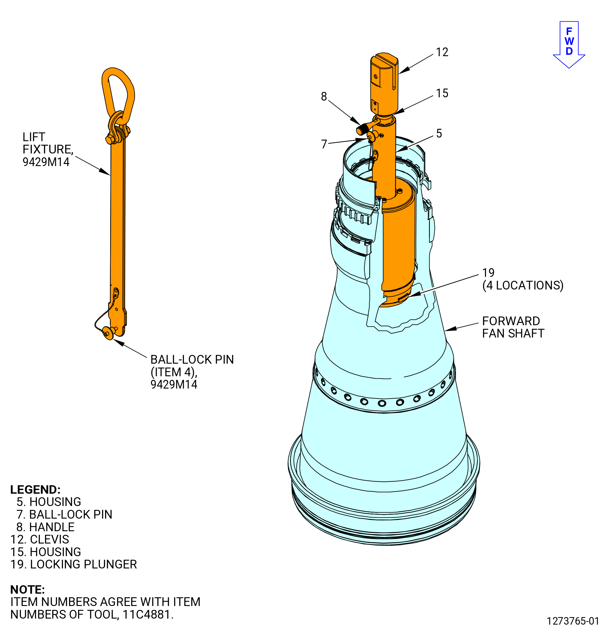
| (1) | Install the 11C4881 handling fixture on the forward fan shaft of the No. 2 ball bearing assembly (20-030 , 72-00-02) (SIN 01200). Refer to Figure 514 and do as follows: |
| WARNING: |
|
| (a) | Attach an overhead hoist to lift the 9429M14 lift fixture. |
| (b) | Align the 9429M14 lift fixture with the pinholes in the clevis (item 12) of the 11C4881 handling fixture. |
| (c) | Install the ball-lock pin (item 4) of the9429M14 lift fixture to attach the 11C4881 handling fixture to the 9429M14 lift fixture. |
| CAUTION: |
|
| (d) | Make sure that the ball-lock pin (item 7) is in the housing (item 5) hole marked UNLOCKED to retract the locking plunger (item 19). |
| (e) | Lift the 11C4881 handling fixture and lower fully into the shaft. |
| (f) | Remove the ball-lock pin (item 7). |
| (g) | Turn the handle (item 8) until the hole in the housing (item 5) marked LOCKED is aligned with the hole in the inner housing (item 15) to engage the plungers (item 19). |
| (h) | Install the ball-lock pin (item 7). |
| (2) | Apply a lift pressure to the No. 2 ball bearing assembly with the 9429M14 lift fixture attached to the 11C4881 handling fixture. |
| Subtask 72-24-00-040-081 |
| (3) | Alternative Procedure Available. Attach a second overhead hoist to the eyebolt (item 44) on the adjustable support of the 9401M62 adjustable stand. Refer to Figure 505. |
| Subtask 72-24-00-040-082 |
| (3).A. | Alternative Procedure. Attach a second overhead hoist with a lift sling to the 9481M78 bracket adapter on the adjustable support of the 9401M62 adjustable stand. Refer to Figure 505. |
| Subtask 72-24-00-040-086 |
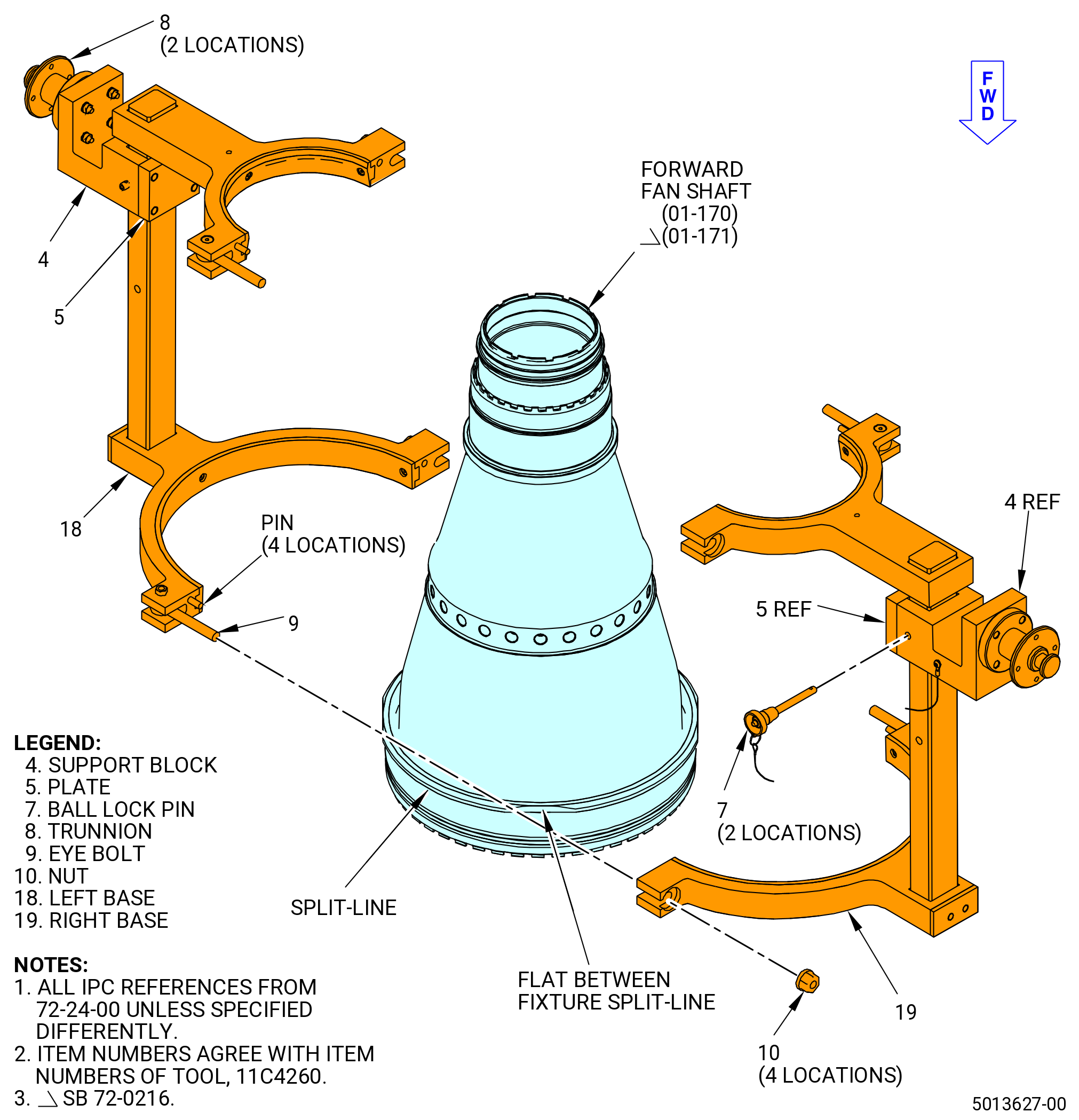
| (4) | Remove the 11C4260 lift/turn fixture from the No. 2 ball bearing assembly as follows. Refer to Figure 515. |
| (a) | Remove the flange nuts (item 10) from the eyebolts (item 9) at four locations. |
| (b) | Separate the left base (item 18) and the right base (item 19) from the No. 2 ball bearing assembly that is attached to the adjustable support on the 9401M62 adjustable stand. |
| WARNING: |
|
| (5) | Lift the No. 2 ball bearing assembly from the 9401M62 adjustable stand. |
| (6) | Remove the left base (item 18) attached to the 9481M78 bracket adapter on the 9401M62 adjustable stand. |
| Subtask 72-24-00-040-014 |
| K. | Remove the No. 2 ball bearing support housing (bearing housing) from the shaft extension on the forward fan shaft as follows: |
| NOTE: |
|
| WARNING: |
|
| (1) | Lift the No. 2 ball bearing assembly with the 9429M14 lift fixture attached to the 11C4881 handling fixture and lower into the 11C3128 puller . Refer to Figure 514. |
| (2) | Remove the 11C4881 handling fixture from the forward fan shaft on the No. 2 ball bearing assembly as follows. |
| (a) | Remove the ball-lock pin (item 7) from the housing (item 5). |
| (b) | Turn the handle (item 8) until the hole in the housing (item 5) marked UNLOCKED is aligned with the hole in the inner housing (item 15) to retract the locking plungers (item 19). |
| (c) | Install the ball-lock pin (item 7) in the housing (item 5). |
| (d) | Remove the 11C4881 handling fixture from the No. 2 ball bearing. |
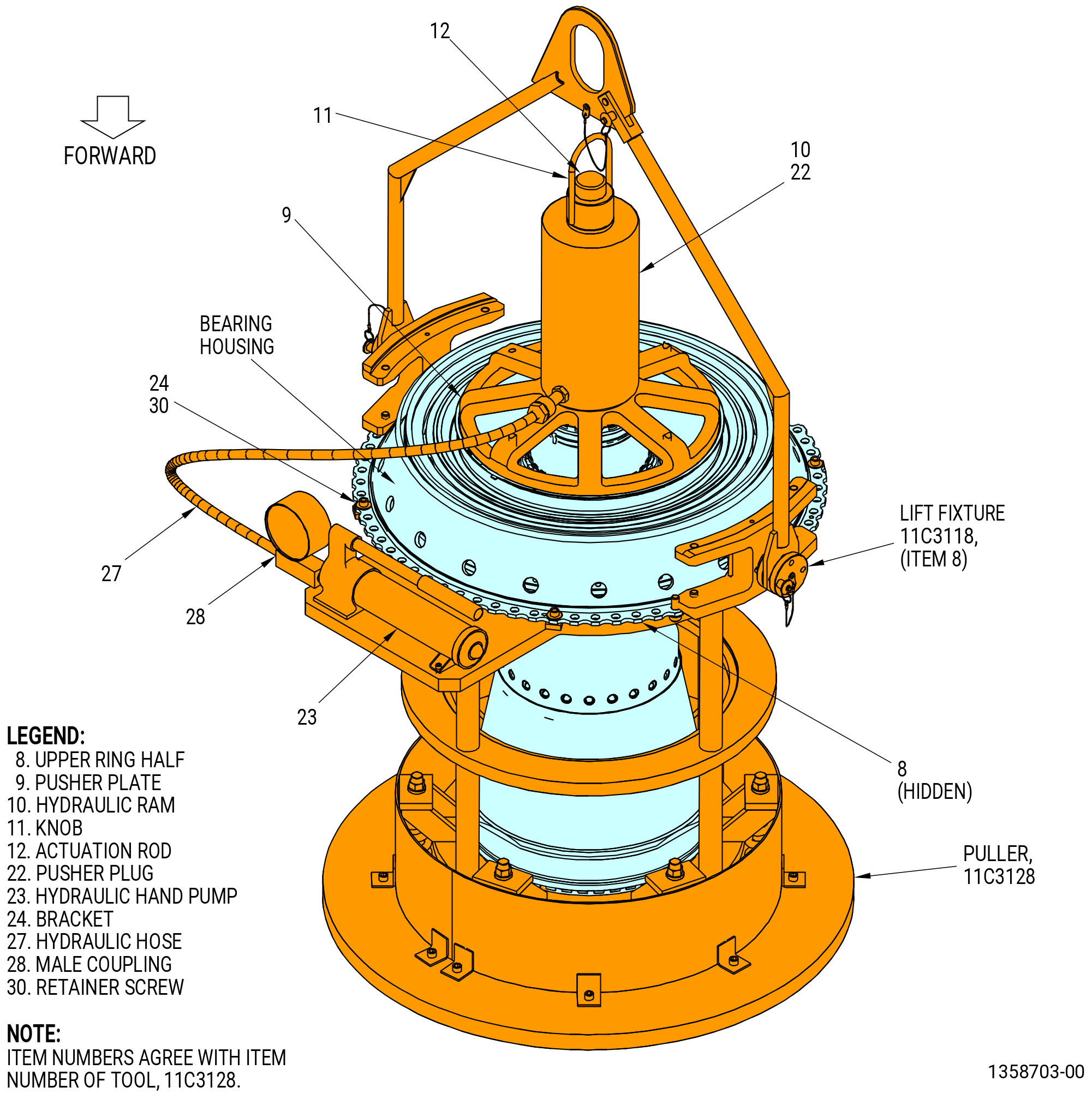
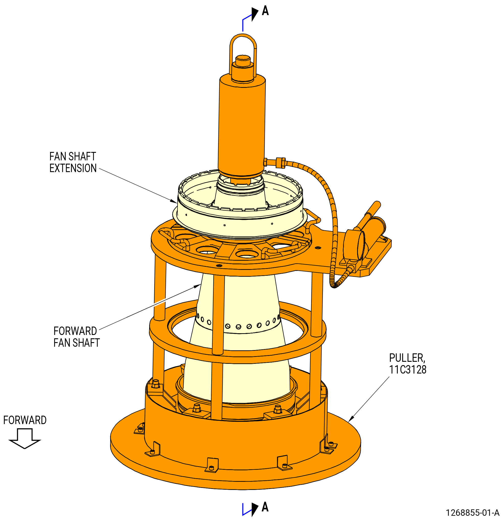
| (3) | Install the 11C3128 puller as follows. Refer to Figure 516. |
| (a) | Attach the brackets (item 24) to the housing assembly with the retainer screws (item 30) at four locations. |
| (b) | Install the actuator rod (item 12) in the shaft. |
| (c) | Attach an overhead hoist to the lift eyes (item 16) at four locations on the pusher plate (item 9) on the shaft extension. |
| (d) | Lift the pusher plate (item 9) and install on the shaft extension on the No. 2 ball bearing assembly and remove the overhead hoist. |
| (e) | Install the hydraulic ram (item 10) on the actuator rod (item 12). |
| (f) | Install the knob (item 11) on the actuator rod (item 12). |
| (g) | Attach the hydraulic hose (item 27) to the male coupler (item 28). |
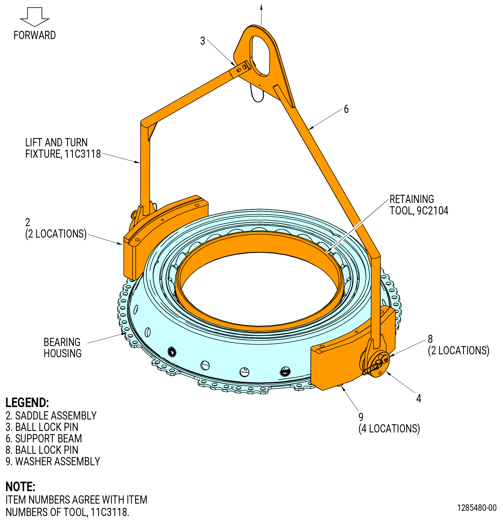
| (4) | Attach the 11C3118 lift fixture to the bearing housing as follows. Refer to Figure 517. |
| (a) | Move the leg of the support beam (item 6) in until the boltholes of the saddle assemblies (item 2) align with the boltholes of the housing flange at the 3:00 and 9:00 o'clock positions. |
| (b) | Attach each saddle assembly (item 2) to the housing flange with two washer assemblies (item 9). |
| 1 | Install the first washer assembly in the 3:00 o'clock saddle assembly at bolthole No. 10 CW from the 6:00 o'clock position, forward looking aft (FLA). |
| 2 | Install the first washer assembly in the 9:00 o'clock saddle assembly at bolthole No. 12 counterclockwise (CCW) from the 6:00 o'clock position (FLA). |
| (c) | Install the ball-lock pin (item 3) to lock the support beam (item 6) in position. Make sure that the ball-lock pins (item 8) are installed. |
| (5) | Actuate the hydraulic hand pump (item 23) to move the hydraulic ram (item 10) until the bearing races are pushed off the shaft extension on the forward fan shaft. |
| (6) | Release the pressure from the hydraulic hand pump (item 23). At the same time, lift the bearing housing (01-110) (SIN 01203) with the hoist until the bearing housing is removed from the forward fan shaft. |
| (7) | Remove the hydraulic ram (item 10) from the actuator rod (item 12). |
| Subtask 72-24-00-040-054 |
| (8) | Remove the No. 2 ball bearing assembly from the shaft extension on the forward fan shaft as follows: |
| CAUTION: |
|
| CAUTION: |
|
| CAUTION: |
|
| (a) | Remove the bearing aft inner race. |
| (b) | Remove the retainer screws (item 30) that attach the bearing housing to the brackets (item 24) of the 11C3128 puller. |
| WARNING: |
|
| (c) | Lift the bearing housing off of the bearing ball and cage assembly and put the housing assembly on a clean surface. |
| (d) | Remove the bearing ball and cage assembly from the bearing inner race. |
| (e) | Put the bearing on a piece of C10-009 greaseproof paper until the outer race is removed. |
| (9) | Install the 9C2104 retaining tool on the No. 2 ball bearing. Refer to Figure 517. |
| (10) | Lift the bearing housing and rotate as follows: |
| (a) | Remove the ball-lock pins (item 8) at two locations and rotate the bearing housing to put the aft end down. |
| (b) | Install the ball-lock pins (item 8). |
| (11) | Make sure that the housing has left-hand threads. The housing is marked LH THREAD at the 6:00 o'clock position on the outer aft flange. |
| NOTE: |
|
| Subtask 72-24-00-040-077 |
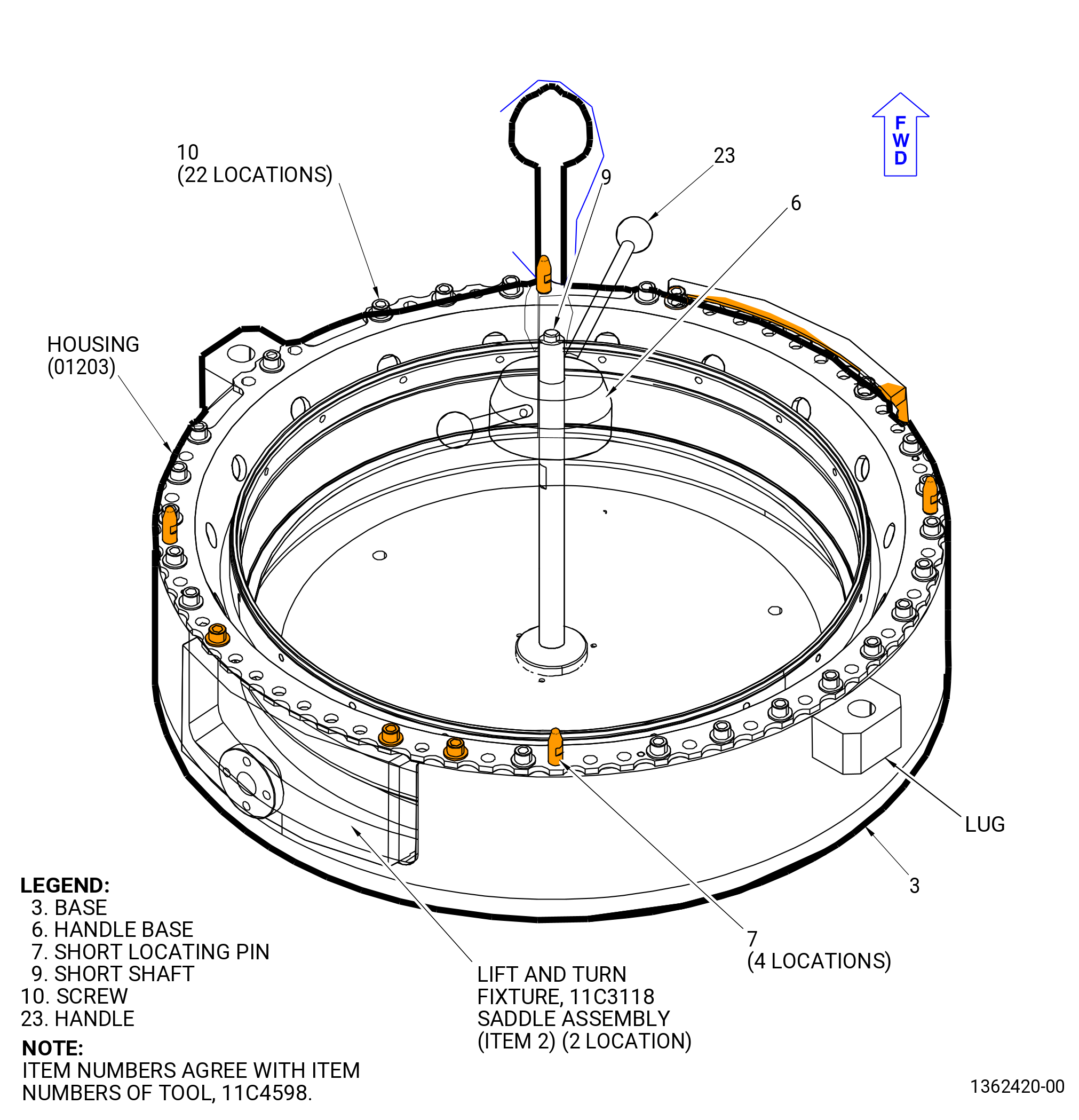
| L. | Install the bearing housing (01203) on the 11C4598 housing stand as follows. Refer to Figure 518. |
| (1) | Find the top vertical centerline of the housing. |
| NOTE: |
|
| (2) | Remove the handle base (item 6 and 23) from the shaft of the 11C4598 housing stand. |
| (3) | Remove the short shaft (item 9) from the base (item 3). |
| (4) | Align the bolthole at the top vertical centerline of the bearing housing with the lug marked “TOP VERT”. |
| (5) | Make sure that the saddle assemblies (item 2) of the 11C3118 lift fixture are aligned in the recess on the base (item 3) of the 11C4598 housing stand. |
| WARNING: |
|
| (6) | Lower the bearing housing onto the base (item 3) and above the four short locating pins (item 7). |
| (7) | Make sure that the boltholes of the bearing housing align with the boltholes of the base (item 3). |
| (8) | Install the 22 screws (item 10) equally spaced in the boltholes of the flange to attach the housing to the base (item 3). Tighten the screws (item 10). |
| (9) | Remove the ball-lock pin (item 3) of the 11C3118 lift fixture and pull the support beam (item 6) out of the way. Refer to Figure 517. |
| (10) | Remove the ball-lock pin (item 8) at two locations and remove the 11C3118 lift fixture from the saddle assembly (item 2). |
| Subtask 72-24-00-040-056 |
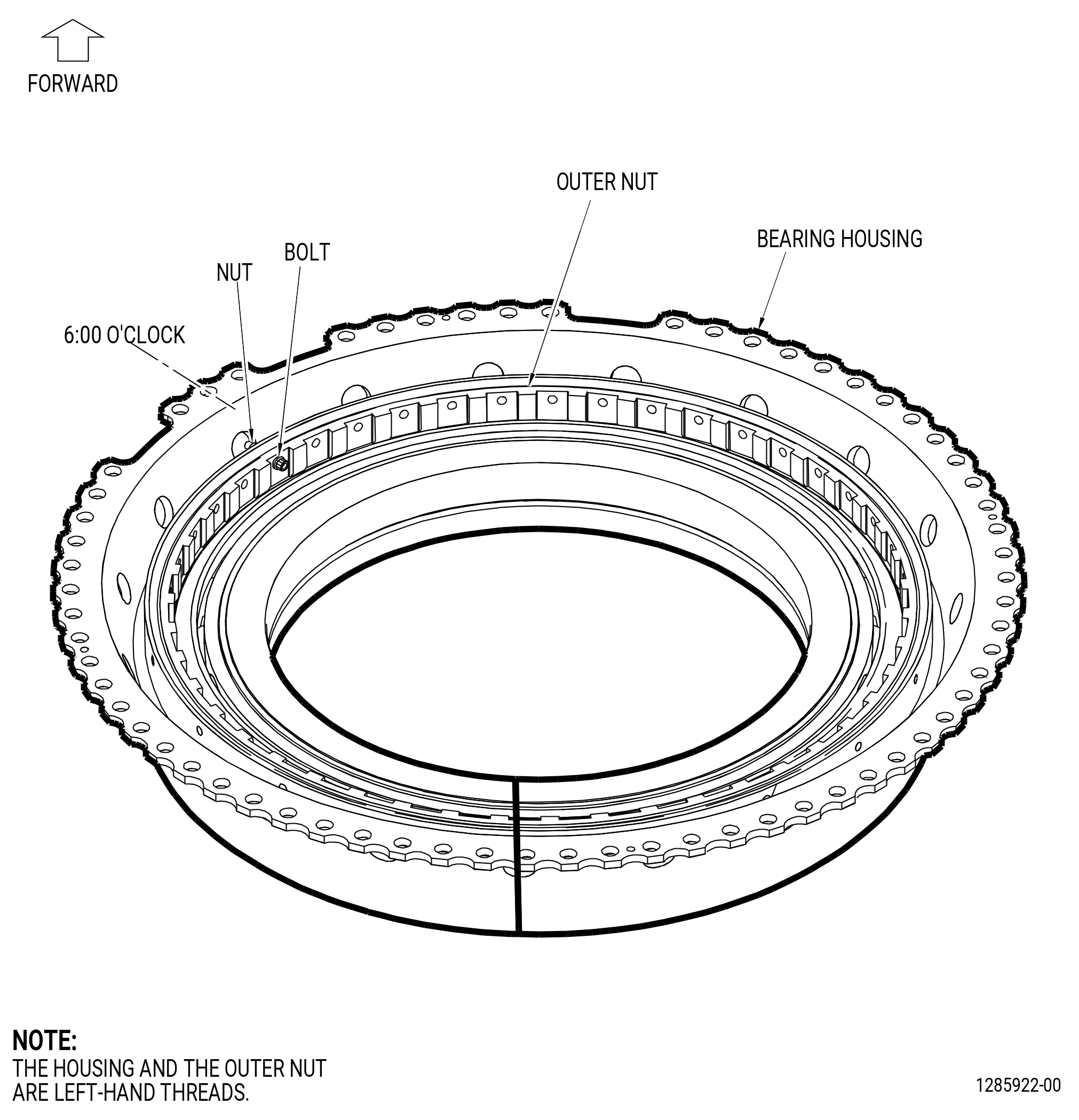
| M. | Remove the No. 2 bearing outer race retaining nut (outer nut) as follows: |
| (1) | Remove the bolt and nut at the 6:00 o'clock position from the No. 2 ball bearing housing and outer nut. Refer to Figure 519. |
| CAUTION: |
|
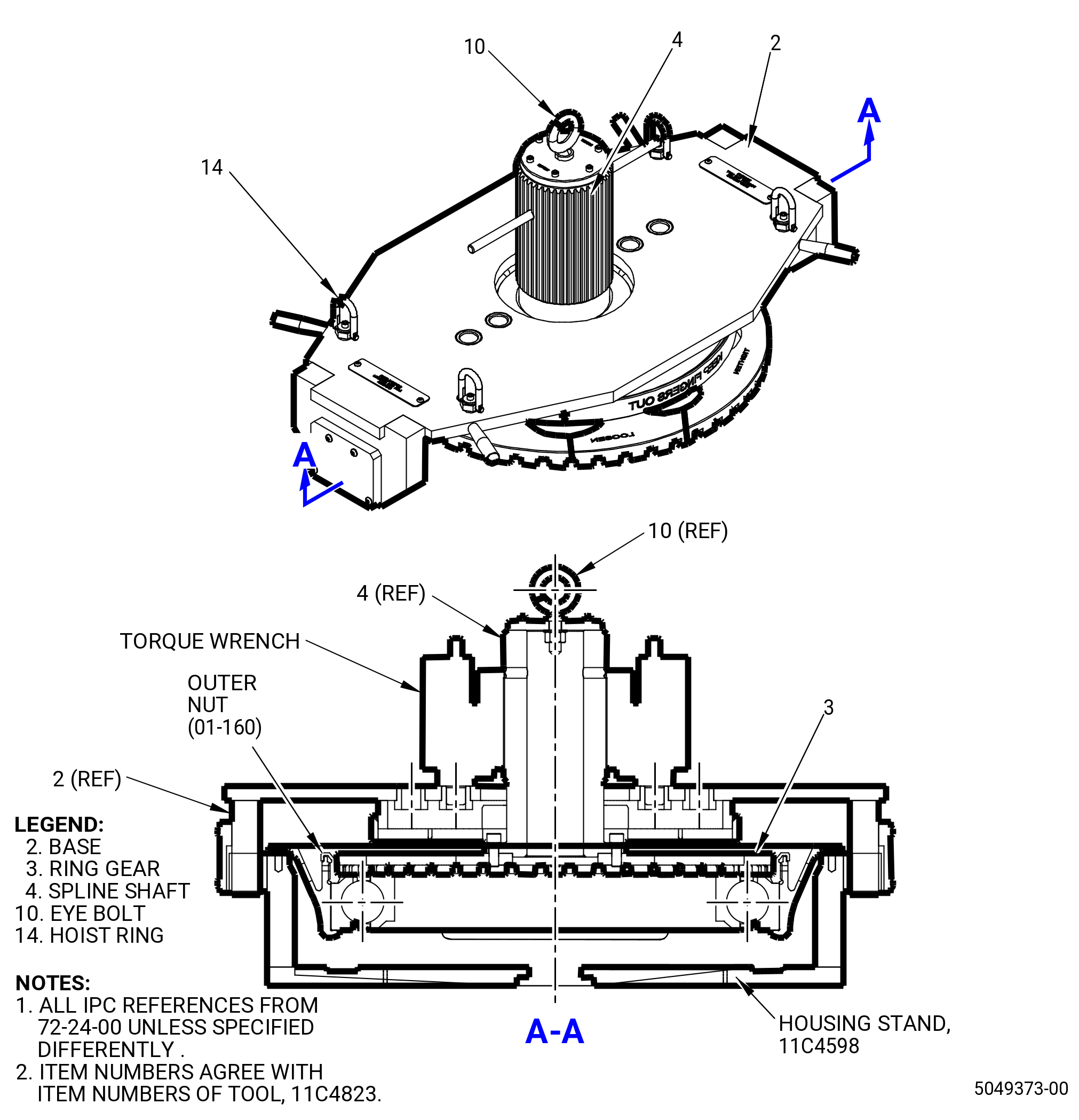
| (2) | Install the 11C4823 torque adapter. Refer to Figure 520 and do as follows: |
| NOTE: |
|
| WARNING: |
|
| (a) | Lift the spline shaft (item 4) and ring gear (item 3) with the eye bolt (item 10). Use a sling with proper capacity. |
| (b) | Lower the ring gear (item 3) until its castellation is engaged with the outer plain nut. Align the ring gear (item 3) to the outer plain nut. |
| (c) | Lift the base (item 2) by using the four hoist rings (item 14). Use a sling with proper capacity. Slide and center the base (item 2) onto the stand, assembly disassembly No. 2 bearing 11C4598 housing stand. Refer to Figure 519. |
| (3) | Lift and install the torque multiplier by aligning its splines with the splines of the ring gear (item 3). Lift the torque multiplier with an overhead hoist. |
| (4) | Align torque multiplier pins with the holes in the base (item 2). Refer to Figure 520. |
| CAUTION: |
|
| (5) | Operate the torque multiplier CW to loosen the outer nut. The outer nut has left-hand threads. |
| NOTE: |
|
| NOTE: |
|
| (6) | Remove the torque multiplier with an overhead hoist. |
| (7) | Remove the 11C4823 torque adapter with an overhead hoist. |
| (8) | Remove the outer nut. |
| (9) | Deleted. |
| Subtask 72-24-00-040-057 |
| N. | Remove the No. 2 bearing outer race from the bearing housing as follows: |
| WARNING: |
|
| (1) | Lower the 11C3118 lift fixture and attach the support beam (item 6) to the saddle assemblies (item 2) with the two ball-lock pins (item 8). Refer to Figure 517. |
| (2) | Lift the bearing housing from the 11C4598 housing stand. |
| NOTE: |
|
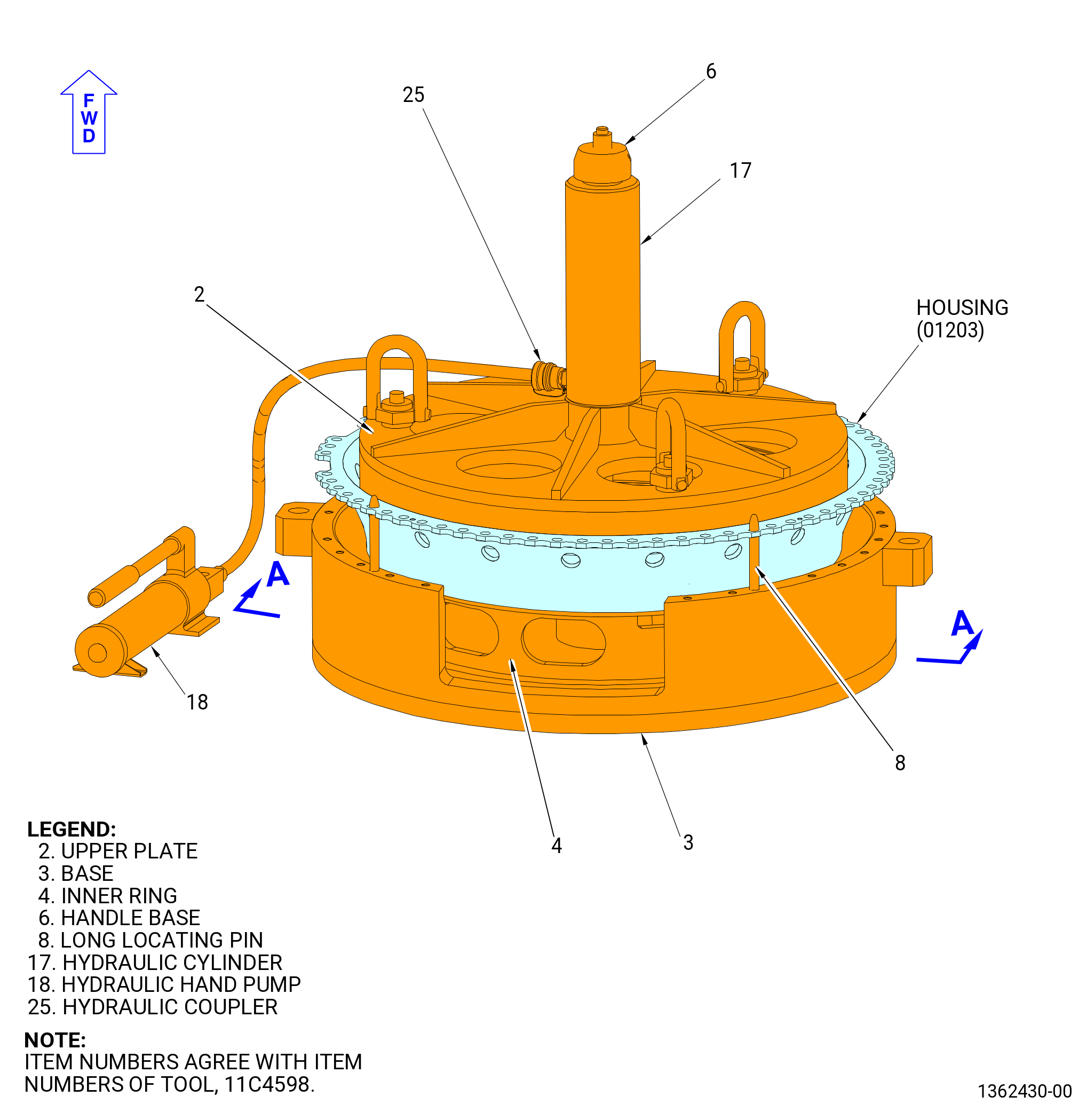
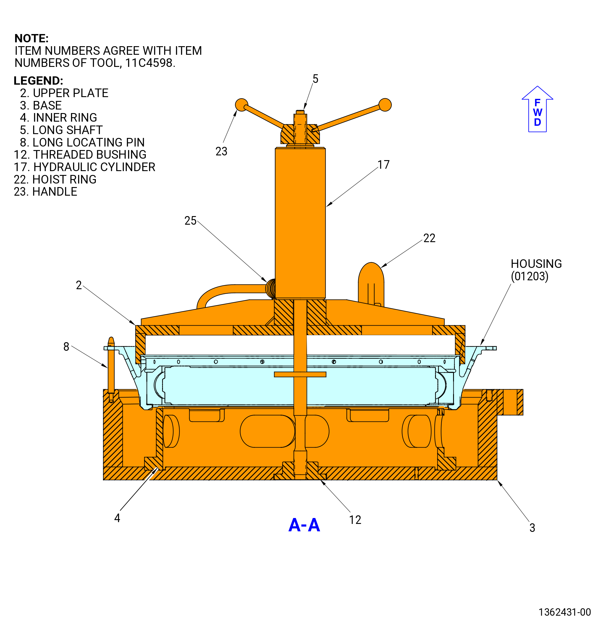
| (3) | Install the inner ring (item 4) of the 11C4598 housing stand on the groove of the base (item 3). Refer to Figure 521. |
| (4) | Install the long shaft (item 5) on the threaded bushing (item 12). |
| (5) | Install the long locating pins (item 8) on the base (item 3). |
| (6) | Lower the bearing housing, forward end up, onto the long locating pins (item 8) and the inner ring (item 4). |
| (7) | Attach a three-piece sling to the hoist rings (item 22) at three locations on the upper plate (item 2). |
| (8) | Lift the upper plate (item 2) and lower onto the bearing housing. |
| (9) | Remove the three-piece sling. |
| (10) | Install the hydraulic cylinder (item 17) and handle assembly (item 6 and 23) onto the long shaft (item 5). |
| NOTE: |
|
| (11) | Operate the hydraulic hand pump (item 18) to push the No. 2 bearing housing from the outer race. |
| (12) | Remove the handle assembly (item 6 and 23) and the hydraulic cylinder (item 17) from the long shaft (item 5). |
| (13) | Remove the long shaft (item 5) from the threaded bushing (item 12). |
| (14) | Attach a three-piece sling to the hoist swivel rings (item 22) at three locations on the upper plate (item 2). |
| (15) | Lift to remove the upper plate (item 2) from the housing. |
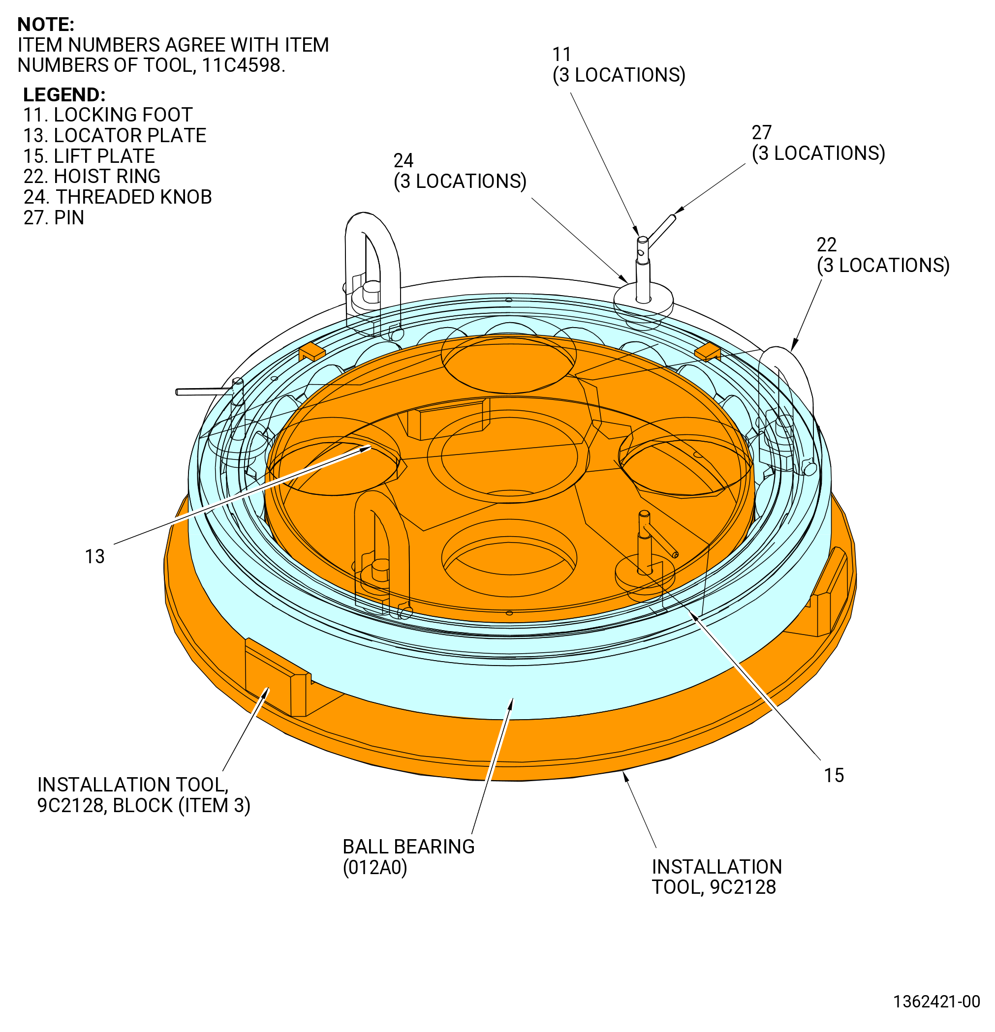
| (16) | Install the 11C4598 subassembly housing stand (items 11, 13, 15, 22, 24, 26, and 27) on the No. 2 Bearing as follows. Refer to Figure 522. |
| (a) | Attach three slings with a minimum capacity of 650 lb (295 kg) to the three hoist rings (item 22) of the 11C4598 subassembly housing stand (items 11, 13, 15, 22, 24, 26, and 27). |
| (b) | Put the 11C4598 subassembly housing stand (items 11, 13, 15, 22, 24, 26, and 27) above the No. 2 ball bearing outer race. |
| (c) | Turn the threaded knob (item 24) CCW until the protruding length of the looking foot (item 11) is sufficient to install the No. 2 ball bearing outer race. |
| (d) | Put the three Pins (item 27) pointed to the “open” position marked on the lift plate (item 15). |
| (e) | Lower the 11C4598 subassembly housing stand (items 11, 13, 15, 22, 24, 26, and 27) into the No. 2 ball bearing outer race. |
| (f) | To secure the No. 2 ball bearing outer race, put the three pins (item 27) in the “close” position and turn the threaded knob (item 24) CW by hand. |
| (g) | Make sure that the 9C2104 retaining tool is installed to hold the balls of the ball bearing in position. |
| WARNING: |
|
| (h) | Lift the No. 2 bearing assembly and put on the block (item 3) of the 9C2128 installation tool. |
| (i) | Put the three pins (item 27) pointed to the “open” position marked on the lift plate (item 15). |
| (j) | Remove the cage from the outer race and wrap the two parts in C10-009 paper, greaseproof and put in a protective container. |
| NOTE: |
|
| (17) | Lower the 11C3118 lift fixture and attach the support beam (item 6) to the saddle assemblies (item 2) with the two ball-lock pins (item 8). Refer to Figure 517. |
| (18) | Lift and remove the bearing housing from the 11C4598 housing stand. Put the bearing housing on a clean work surface. |
| Subtask 72-24-00-040-058 |
| O. | Remove the fan shaft extension from the forward fan shaft as follows. Refer to Figure 523. |
| NOTE: |
|
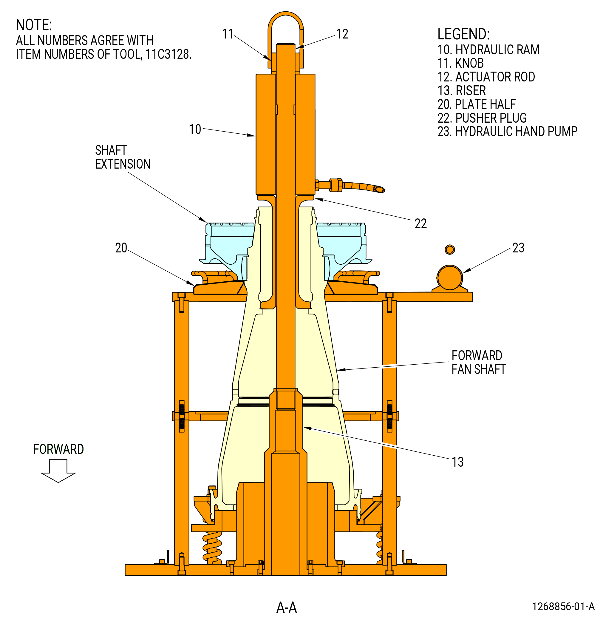
| (1) | Install the plate half (item 20) of the 11C3128 puller at two locations onto the shaft assembly. |
| (2) | Install the actuator rod (item 12), pusher plug (item 22), hydraulic ram (item 10) and knob (item 11) on the shaft. |
| (3) | Thread the hydraulic ram (item 10) onto the riser (item 13). |
| (4) | Connect the hydraulic ram (item 10) to the hydraulic hand pump (item 23). |
| WARNING: |
|
| (5) | Attach a three-piece sling to the 9C2107 installation tool. |
| (6) | Install the 9C2107 installation tool on the shaft extension as follows. Refer to Figure 524. |
| (a) | Loosen the knurled knobs (item 6) to unlock the locking plungers (item 5) and put the feet outward. |
| (b) | Pull the locking plungers (item 5) down to allow installation of the base (item 2) on the ball bearing stop face. |
| (c) | Attach a three-legged sling to the hoist arms (item 3) to lift the 9C2107 installation tool. |
| (d) | Align the pins (item 12) with the OD of the shaft extension. |
| (e) | Lower the 9C2107 installation tool onto the shaft extension until the base (item 2) is on the ball bearing stop face. |
| (f) | Move the locking plungers (item 5) and engage the shaft extension. |
| (g) | Tighten the knurled knobs (item 6) to hold the shaft extension between the locking plungers (item 5) and the base (item 2). |
| (7) | Operate the hydraulic hand pump (item 23) to push the fan shaft extension off of the forward fan shaft. |
| (8) | Put a support between the fan shaft extension and plate half (item 20) of the 11C3128 puller. |
| (9) | Release the pressure from the hydraulic hand pump (item 23) and remove the hydraulic pump. |
| (10) | Lift the fan shaft extension with the 9C2107 installation tool and put it on a clean work surface. |
| (11) | Remove the 9C2107 installation tool from the shaft extension. |
| Subtask 72-24-00-040-078 |
| P. | Alternative Procedure Available. Install the 11C4881 handling fixture to the aft end of the forward fan shaft. Refer to Figure 525 and do as follows: |
| WARNING: |
|
| (1) | Attach an overhead hoist to lift the 9429M14 lift fixture. |
| (2) | Align the 9429M14 lift fixture with the holes in the clevis (item 12) of the 11C4881 handling fixture. |
| (3) | Install the ball-lock pin (item 4) of the 9429M14 lift fixture to attach the 11C4881 handling fixture to the 9429M14 lift fixture. |
| CAUTION: |
|
| (4) | Make sure that the ball-lock pin (item 7) is in the housing (item 5) hole marked UNLOCKED to retract the locking plunger (item 19). |
| (5) | Lift the 11C4881 handling fixture and lower it fully into the forward fan shaft. |
| (6) | Remove the ball-lock pin (item 7). |
| (7) | Turn the handle (item 8) until the hole in the housing (item 5) marked LOCKED is aligned with the hole in the inner housing (item 15) to engage the plungers (item 19). |
| WARNING: |
|
| (8) | Lift the forward fan shaft from the 11C3128 puller and put on a clean work surface. Remove the 9429M14 lift fixture from the 11C4881 handling fixture. Do not remove the 11C4881 handling fixture at this time. |
| NOTE: |
|
| Subtask 72-24-00-040-085 |
| P.A. | Alternative Procedure. Install the 11C4260 lift/turn fixture on the forward fan shaft (01-170) (SIN 81002) or (01-171) (SIN 81002). Refer to Figure 515 and do as follows: |
| NOTE: |
|
| WARNING: |
|
| (1) | Attach an overhead hoist with a lift sling to the left base (item 18). |
| (2) | Lift the left base (item 18) on the forward fan shaft. |
| (3) | Make sure to put the flats of the forward fan shaft between the split-line on the left base (item 18). |
| (4) | Do not install the left base (item 18) split-line on the flat. |
| NOTE: |
|
| (5) | Attach an overhead hoist with a lift sling to the right base (item 19). |
| (6) | Lift the right base (item 19) on the forward fan shaft. |
| (7) | Align the pins in the left and right base with the holes in the left and right base. |
| (8) | Install the eye bolts (item 9) and attach with the nuts (item 10). Tighten the nuts in a crisscross pattern. |
| Subtask 72-24-00-040-066 |
| Q. | Alternative Procedure Available. Attach the 9429M14 lift fixture to the 11C4881 handling fixture. Refer to Figure 525 and do as follows: |
| WARNING: |
|
| (1) | Attach an overhead hoist to the 9429M14 lift fixture. |
| (2) | Align the 9429M14 lift fixture with the holes in the clevis (item 12) of the 11C4881 handling fixture. |
| (3) | Attach the 9429M14 lift fixture with the ball-lock pin (item 4) to the 11C4881 handling fixture. |
| Subtask 72-24-00-040-083 |
| Q.A. | Alternative Procedure. Attach the 9471M24 lift/turn fixture to the 11C4260 lift/turn fixture. Refer to Figure 526 and do as follows: |
| WARNING: |
|
| (1) | Attach an overhead hoist to the lift plate (item 3) of the 9471M24 lift/turn fixture. |
| (2) | Attach the cable assembly (item 9) to the lift plate (item 3) with the forged anchor shackle (item 12). Make sure that they have the same number of holes on the outboard side of the hoist assemblies on the lift bar. The hoist assemblies must be perpendicular to the lift bar when attached to the 11C4260 lift/turn fixture. |
| (3) | Open the piston (item 7) of the 9471M24 lift/turn fixture and install the lock plate adapter (item 4) on the trunnion of the 11C4260 lift/turn fixture. |
| (4) | Insert the ball-lock pin (item 10) in the lock plate adapter (item 4). |
| Subtask 72-24-00-040-084 |
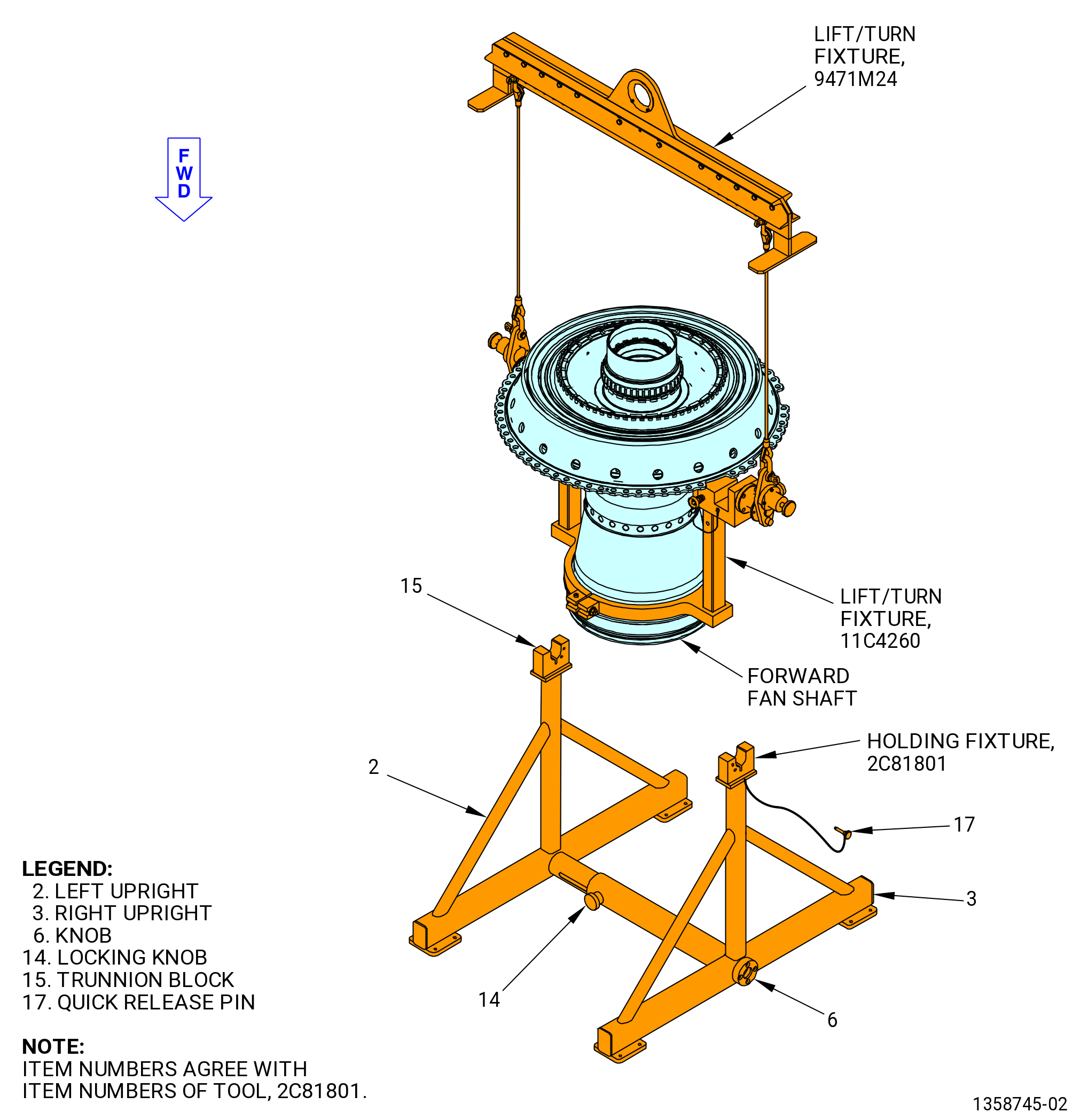
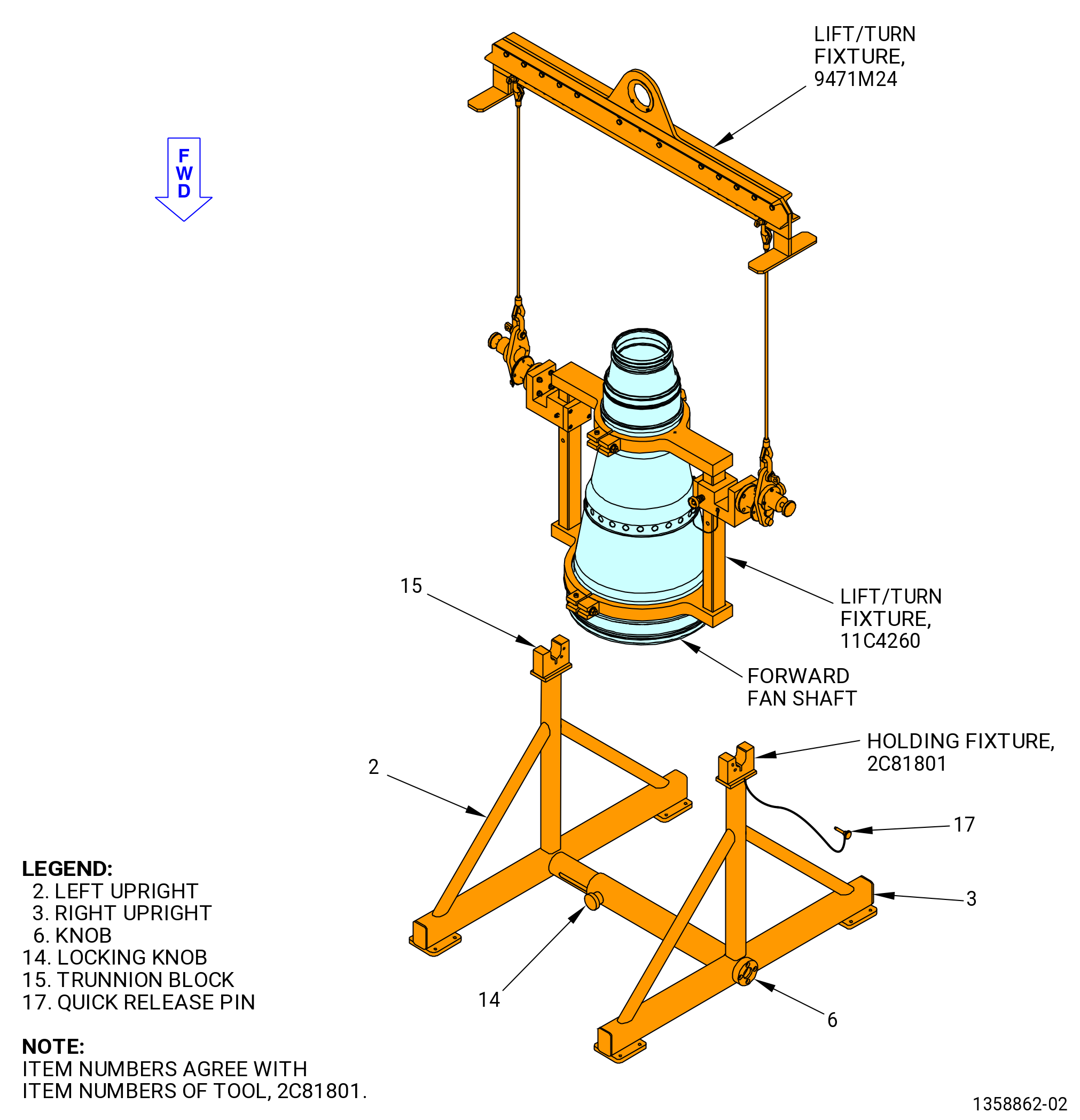
| R. | Install the forward fan shaft on the 2C81801 holding fixture as follows. Refer to Figure 527. |
| (1) | If necessary, adjust the distance between the left upright (item 2) and the right upright (item 3) to get the correct distance between the two trunnion blocks (item 15) as follows: |
| (a) | Turn the locking knob (item 14) CCW to loosen the left upright (item 2) from the right upright (item 3). |
| (b) | Turn the knob (item 6) CW or CCW to get the correct distance between the two trunnion blocks (item 15). |
| (c) | Turn the locking knob (item 14) CW to tighten the left upright (item 2) to the right upright (item 3). |
| (2) | Remove the two quick release pins (item 17) from the trunnion blocks (item 15). |
| (3) | Install the forward fan shaft with the 11C4260 lift/turn fixture in the 2C81801 holding fixture. Make sure that the 11C4260 lift/turn fixture is correctly installed in the trunnion blocks (item 15). |
| (4) | Install the two quick release pins (item 17) in the trunnion blocks (item 15). |